default

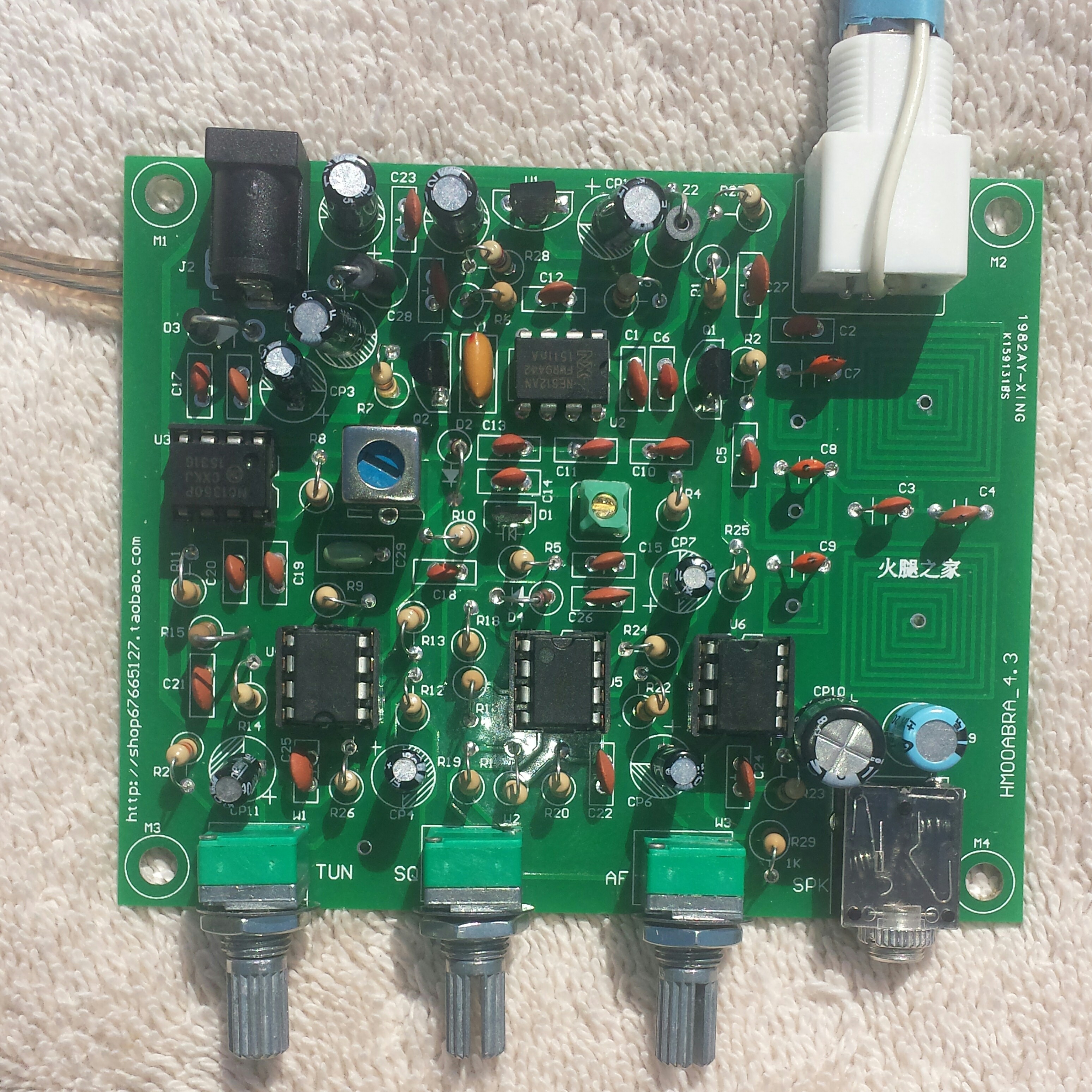
2018-10-06 Air Band Radio Kit HMOOABRA_4.3 Part 2

Posted to FB group Building Transistor Radios 2018-10-06

First part is here.

I noticed that my photo didn’t get added to the photos tab, So I’m trying again to add it.

I got a fresh start this Sat. morning. I used another little air band receiver to listen for the LO from this one. I turned the tuning pot to minimum which should be 118.00 MHz. I then set the other receiver to 118 + 10.7 or 128.7 MHz. I used a nylon tuning wand to tune the LO coil’s brass slug until I heard the LO fully quiet at 128.7. The speaker has hiss at this setting.

I then set the little receiver for 130, 132, 134, 136, and 138.0 MHz (highest it would go), and each time I could hear the LO in the little receiver as I advanced the tune pot. So the LO is oscillating all the way up to 138. But with the brass slug out most of the way, as soon as I tuned to 130, the hiss from the speaker went down to nothing and stayed quiet for all the other frequencies, too. This is puzzling.

I could hear transmissions on some frequencies in the little receiver. There is activity in the band. This little receiver uses a pair of ear buds for listening, and the antenna is the wires of the ear buds. So the transmissions have plenty of strength to be heard on a short lengths of wire, which is what I’m using for this receiver. But I have heard nothing but hiss on this receiver or no hiss, wherever I have tuned it.

I’m even more puzzled.

Update late afternoon – I forgot I had my Gy560 frequency counter in the drawer. I pulled it out and I touched its antenna to the slug and it gave me a reading. With the tune pot at minimum I set the slug for 118 + 10.7 or 128.7 MHz. As I tuned the pot, I could see the LO frequency go up and up. It should go as high as 136 + 10.7 or 146.7 MHz. But it kept going higher, all the way up to 158.7 MHz. That’s okay, but I would rather have the pot have a smaller range with greater resolution. So I’ll have to change the resistors to get the right range. But first I have to get it to receive a signal.

One thing that bothered me was the PCB coils dipping as high as 200 MHz. So I removed one leg of the C5 DC blocking capacitor, and I soldered a tiny switch to the leg so I can choose to have the antenna signal go through the coils on the PCB or bypass the coils and go directly to Q1. I tried a short length of antenna into the Q1 and it still does not receive any signals across the band. But I can hear the strong signal from my dipmeter at two places on the band, one below and one above the LO frequency, so it seems to be receiving very strong signals.
default

2018-09-28 LM386 Used As Modulator of Final RF Output

From FB group Building Transistor Radios 2018-09-28

I see nothing wrong with using the ‘386 to directly drive the power output stage. It’s cheaper than a transformer.

But I was thinking about how the current was flowing in the ‘386’s output transistors. Normally an electrolytic capacitor blocks any DC from flowing out of pin 5. But when the ‘386 is used to directly modulate the final, the current that would normally flow through the chip’s bottom (current sink or pulldown) transistor instead flows out pin 5 and through the final. The bottom transistor is not doing anything, it can’t current sink or pulldown because the pin 5 has current flowing out only, nothing flows in to be sunk or pulled down. So the ‘386 is effectively running as a current source with just the top (current source or pull-up) transistor.

The point is that the ‘386 chip could be replaced with a single transistor, or two if more gain is needed.

default

2018-09-11 Vectronics Aircraft Radio Kit

I got the Vectronics VEC-131K aircraft band radio kit in the mail yesterday and warmed up the soldering iron to assemble it. It came at a decent price, so some of my complaints seem to be cost cutting measures. It comes with a decent assembly instruction manual, but some of the pages including the schematic were printed from a low resolution graphic, which makes them difficult to read. The Parts Placement Diagram page was not readable and useless. The part numbers are marked on the PC board, so I had to use that.

The assembly time was about 3 hours, but would have been less if I hadn’t hit a few snags – I’ll talk about those later. I would estimate this to be a medium difficulty kit, because it has a lot of parts and there other reasons I’ll get to next.

The instructions get to the point where the two glass diodes are installed. It says to pick the larger glass diode, the 1N270, and I’ll need a magnifying glass to read the markings. But both diodes are the same size, and neither one said 1N270. One said F 5235 so I assumed that was the 1N5235 zener diode. The other diode said 41 BAT, which was not 1N270, so I assumed it was a substitute for the 1N270. I installed it and the zener in their proper places and hoped I got it right.

Another snag was the winding of the three coils. The instructions said to use the length of 24 gauge enameled wire, but I found none in the bags. There were three short lengths of purple hookup wire in the bag, but they didn’t look like it was possible for them to do the job. The instructions say to wind the coils on a 6-32 screw, but the heavy hookup wire would not fit into the threads like they said. So I found some 24 AWG enameled wire that I had and used it instead.

There were seven “103” .01 uF ceramic disk capacitors to be installed into the board. The bag had seven big blue .01 uF capacitors that were rated at 1000 volts and their leads were very wide, making it difficult to install them close to the board. So I got seven smaller .01 uF capacitors from my parts box and used them instead. They could still be a lot smaller, so I may replace them later.

With the rest of the parts properly installed, I finished up the assembly. then the instructions take me through the testing and alignment. I used a short lengths if wire for the antenna, plugged in a speaker, powered it up and turned up the volume but I heard nothing. I heard some clicks and buzzes but that was my cellphone, so I moved it away. I did the procedure “10.7 MHz IF Stage Alignment By Ear” and suddenly the receiver started to put out noise, which was a good sign. There is no squelch control on this radio.

The instructions said to “Set the Local Oscillator Tuning Range Using the Signal Generator” but I don’t have a signal generator that can go to 120 MHz. So instead I used the “Setting the LO Tuning Range Using Off-air Signals” procedure. I tuned the frequency control, but it was super sensitive and a very small change covered many channels. I think this 10k potentiometer needs to be replaced with a multiturn pot that will give finer control of the frequency setting. Also the volume control seems to be linear, not logarithmic. When I turn it to minimum the speaker is silent. But if I turn the pot just slightly above minimum the volume gets very loud very quickly. If it was logarithmic, the volume would be normal over a much wider range of the pot.

I have been listening to the local airport radio traffic with just a few feet of wire connected to the RCA antenna jack. But I don’t know what frequency I’m listening to. I need to get some way of calibrating the dial so I can choose 121.8 MHz, the frequency for the big jets.

Update 12 Sep.

I made a modification to the volume control. I soldered a 680 ohm resistor between the center wiper pin and the pin that’s common negative. This makes the volume control less sensitive so it doesn’t get so loud when it’s barely turned up. The resistor could be lower, maybe 560 or 470 ohms, to make it even less sensitive.

The second modification was to add a 1k pot in series with R7. I unsoldered the negative lead of the 2.2k resistor R7 and soldered a short piece of wire to the lead and to the center wiper pin of a 1k pot. I soldered another short wire to the other ‘cold’ pin of the pot and to the hole where the 2.2k resistor lead was. This is much easier to tune to a channel than the main 10k tuning pot.

Now I need to print a list of the John Wayne Airport frequencies.

default

2018-09-08 Skunk!

From FB comment to Kate Jesse’s skunk visiting her back yard, 2018-09-12

One time I was on guard duty at the Artillery Hq. in Minneapolis, standing in the 3′ by 3′ guard house at the front gate. I saw something crawling under the fence several yards away, and when I saw the white stripes, I knew it was a skunk! I wasn’t sure what to do, run or what. No door on the guardhouse, the skunk could’ve walked right in! The M1 carbine was useless, no ammo! I just hoped and prayed he’d leave me alone. Skunk waddled off into the brush, and I breathed a sigh of relief. 😱

default

2018-09-07 Q of an Inductor

from FB group Building Transistor Radios, 2018-09-07

Tom Miller
Say a capacitor or inductor has a Q of 100. The losses are about 1/100 of the energy in the component. In a tuned circuit the capacitor Q is usually much higher than this – it has lower losses, so the more important is the Q of the inductor.

The inductor’s copper wire has resistance so there is some loss in the resistance. If it has a core other than air, the losses in the core’s magnetic field add to the total. The core is made of small particles of material to reduce eddy currents, which reduces the losses. The copper wire losses can get higher because of skin effect, which is why Litz wire is used to reduce the skin effect.

default

2018-09-03 Nuclear Power Is Not Economical

from YouTube video TEDx talk comment pro nuclear power, see

2018-09-04

To paraphrase an earlier comment:
“Wow! Spread the word! There is so much *left*out* with this talk!”
Did you notice he left out any mention of the economic aspects of nuclear power generation?

There are THREE nuclear power plants that are sitting partially built and recently abandoned due to delays and cost overruns. (V.C. Summer #2, #3 in SC, and Vogtle #3 in Georgia, see this list https://en.m.wikipedia.org/wiki/List_of_cancelled_nuclear_reactors_in_the_United_States). No utility with any common sense is going to spend tens of billions and more than ten years for a nuclear power plant to come online!

The builder of the plants, Westinghouse, went bankrupt and left creditors with hundreds of millions of debt.

The US government promised they would dispose of the spent nuclear fuel waste, but they reneged and the taxpayer has had to pay for multi-hundred million dollar lawsuits from the utility companies.

The nuclear fuel, mostly enriched uranium, is *not* renewable fuel, it is a finite resource just like fossil fuels.

And the decommissioning of each old nuclear power plant and storing the spent nuclear fuel for thousands of years costs billions of dollars. That is really going to hurt the future generations!

It doesn’t matter if the nuclear power plants are good for the environment or not. As long as they are not economical and can’t be built on time and within budget, they are a non-starter.

default

2018-09-02 Mims Mistakes In Audio Amplifier

From FB group Building Transistor Radios, 2018-09-02

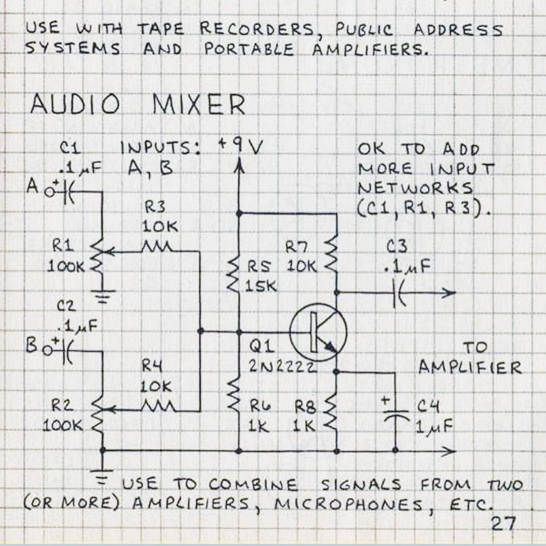
I already see one mistake. On p.27, Audio Mixer.
The R6 is only 1k. The voltage divider R5 and R6 will give a voltage less than 0.6 at Q1’s base, which means Q1 will not be forward biased enough and the circuit won’t work or else sound distorted.

R6 needs to be higher to give 1.1 volts at the base. A close value for R6 would be 2.2k. Better choices for R5 and R6 would be 33k and 4.7k respectively.

C1 and C2 are in the wrong place. When the R1 and R2 volume controls are adjusted, the DC bias on Q1 will be changed. The C1 and C2 capacitors should be moved to the right of R3 and R4 to block the DC bias to the base of Q1. It might help if C1 and C2 were larger, 1 uF or 10 uF.

The value of C4 is too low and the low frequencies will sound weak. Change C4 to 100 uF.

Like I said, you will probably find many more errors and omissions in Mims’ books.

https://www.zpag.net/Electroniques/Kit/Radio_Shack_-_Engineer%27s_Mini-Notebook_-_Basic_Semiconductor_Circuits.pdf

default

2018-09-01 Stop Plagiarizing And Be Self-sufficient

From FB group Arduino projects, 2018-09-01

Attilio Volpe
This group is moderated and if you cause problems, you can be banned. But on Usenet newsgroups, where all this ‘social media’ stuff started decades ago, the groups were not moderated. If you made a mistake, you had hundreds of replies telling you to Shut the F*** up! So you had to not make that mistake again!

The first thing you learned is to *never* ask someone else for their intellectual property, such as program code, diagrams or schematics, etc. You were expected to be able to understand what you were told to do! If the person said “I fixed the problem by doing this”, you were expected to understand and *learn on your own* to fix that problem! You were expected to be self-sufficient and be able to wipe your own ass, not expect to have someone else wipe it for you! If you asked for a program, you would be shunned by everyone else, and if you ever asked for help again, you would be ignored.

But that’s not how these “students” act nowadays. They expect you to hold their hand and never let go until the project is working, and they have contributed almost nothing of their own. Except their constant whining that their code does not compile or run or do what they expect it to do. These are the followers, who will never be leaders and help advance technology.
😥😥😥😥😥😥😥

default

2018-08-31 An Old Software Saying

From FB group Bell Telephone… 2018-08-31

Gary Stoutenburg
I love that comparison. 👍

There’s an old IT adage:
“The first 90% of the software takes 10% of the time. The last 10% of the software takes 90% of the time.”
The user interface is a big time and money sink, so a lot of corner cutting is often done there to get the product out the door. Then years later the Rev 1.x and so on finally get the user interface up to standard. Sometimes companies without the resources of the biggest are scrambling to get other or newer products out the door and devote all their effort to those so there is no further updating of older products. That’s just the way it is and the reason why IBM and Ma Bell had so many loyal customers.

default

2018-08-30 Using Radio Signal To Power A Receiver

From FB group Building Transistor Radios 2018-09-01

There are too many ‘gotchas.’ You have to put up a large sized antenna to gather enough power to run the circuit. That means you cannot use this in a city where the properties are too small, due to lack of space. You go to the country where there is enough land for the antenna, and the radio signals are weak.

You have to have a strong signal for enough power. This will overwhelm the other stations on the band. You will hear the strong signal in the background of the other stations.

It’s a better idea to put a small solar cell in the daylight and use its current to recharge a Ni-MH rechargeable cell, or else charge a supercapacitor. The charge should be enough to run the radio for several hours after sunset.

I put a solar cell on the front of a small piece of plywood and a 4 AA cell holder on the back, and put it in the window. It powers a royal blue LED for most of the night.

© RustyBolt.Info/wordpress
CyberChimps