default

2018-11-20 Solder V. IDC Punchdown

from FB group Bell Telephone…

2018-11-22 Happy Turkey day!

I use solder all the time, and I trust it as long as it’s done properly.

But one thing I learned in my decades of telephone work is that the wiring systems the telcos developed were tested and proven before they were deployed, and they were an optimum combination of cost, reliability, effectiveness, and probably most important, conservation of labor. I can see soldering the thousands of pairs in a CO where it’s permanent, but in the field where things are changing, it is much faster and less expensive to use IDC (punch down) connections. In ’98 I brought up the new HQ, three floors worth of crossconnects in under a week until I had callouses on my fingers from handling the crossconnects. Same with several weekends of a major MPOE move. Lots of memories of those. I couldn’t have done it without my punchdown tools.

default

2018-11-19 Depth of Loop Antenna

from FB group Building Transistor Radios 2018-11-19

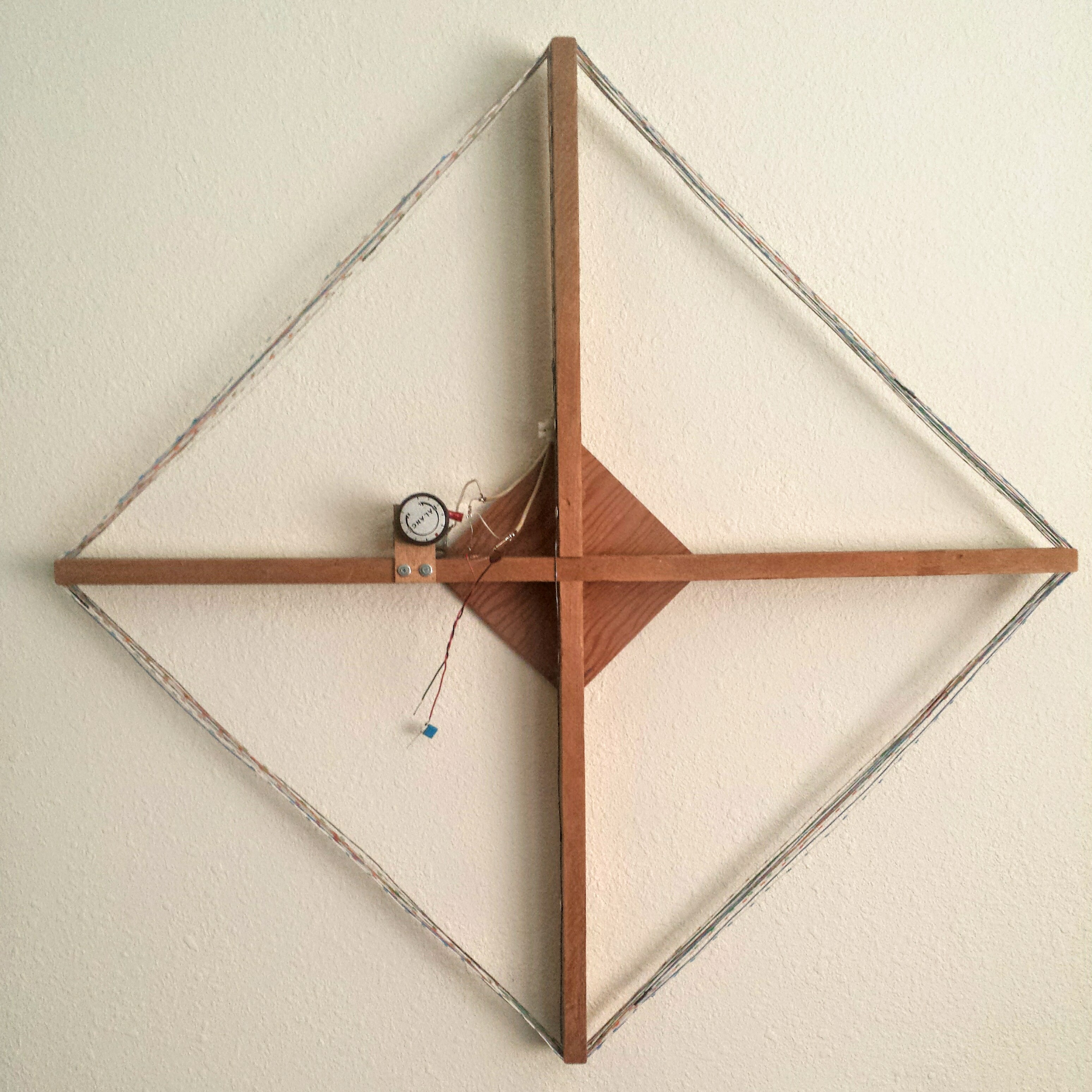
I shared my loop antenna – see photo, and it is somewhat 2 dimensional. The arms are 762mm across but the depth of the windings is only about 35 mm. Compare that to the ferrite loopstick at the other extreme, it’s 10 mm diameter but 100 mm long. I’ve noticed that the loopsticks are quite directional, I can null out a strong station effectively.

I was thinking that if I wound another loop antenna using a square cardboard box, I could cut the box down so the windings have little depth, only 50 mm or 2 inches. This gives a wide ‘figure eight’ pattern with minimal directionality. But should I wind the coil over a deeper box, about the same depth as the width or length? This would give a narrower figure eight pattern with more directionality.

This would take more wire, because spreading the windings over a wider area gives less inductance so more turns will be needed to get the same inductance. Would it be worth doing this to get a narrower pattern? The loop antenna would be bulkier, taking up more room.

default

2018-11-17 Cause Of Bleedover From Radio Stations

from FB group Building Transistor Radios 2018-11-19

IMPORTANT
I used to work for a guy who did radio engineering and would troubleshoot problems such as this ‘bleedover’. For convenience some radio stations colocate their transmitters near or at the same site. Because the signal strengths are very high, the two stations can cross modulate their signals and give sum and difference signals. This can be caused by rust and/or corrosion on metals especially if they are dissimilar metals. Copper oxide was once used for rectifiers. So if the interference is heard on more than one receiver, it could be the radio stations or something nearby is causing the problem. This has been called the Rusty Bolt Effect. If this can be verified, the radio stations should be notified so they can take remedial action.

default

2018-11-16 Low ESR MLCCs

From FB group Building Transistor Radios 2018-11-19

Garry Heard
I’ve found that a problem with using electrolytic capacitors to filter out the RF noise is their internal ESR, effective series resistance. They don’t filter out the RFI as good as they should. I found that MLCCs do a better job, if I used some multi microfarad MLCCs. I got some ‘106’ or 10 uF, 10V MLCCs which have a very low ESR. They’re better than ‘lytics. You can also use tantalums, but they’re somewhat more expensive. Also some RF chokes that are high current and low resistance.

default

2018-11-15 ESD and Weather

from FB group Building Transistor Radios 2018-11-19

Bob Johansen
I worked at a company that had ESD mats on the workbenches, about 1980. We had wrist straps with a 1 Meg resistor in series with the cord to prevent shock hazard. I found that the leads of the resistors were broken but the heat shrink over the resistors hid the breaks.

It gets somewhat dry here but not as bad as where there are real winters with snow. Most of the time we get zapped when we walk across carpet and touch metal objects.

I’ve read that the problem with very dry weather is that static can build up on equipment and discharge without any external influence. So it’s prudent to put a multi megohm resistor to ground to allow discharge.

default

2018-11-07 The 2 Transistor Boy’s Radios

from FB group Building Transistor Radios 2018 Nov 7

I bought some 10 uF, 10 volt MLCC (multilayer ceramic capacitor) capacitors, which do not have the electrolyte so they can’t dry out. They are smaller, too. If they are used for replacements, then radios might last much longer. About the only thing left to go bad is the carbon composition resistors, which tend to increase in resistance. If they are replaced with carbon film resistors, who knows how long these wee beasties might last!

More info on Boy’s radios: http://www.antiqueradios.com/forums/viewtopic.php?t=129192

default

2018-10-26 TV Repair Was A Dying Business

From FB group Building Transistor Radios 2018-10-26

I repaired a lot of old tube TVs, and I saw that the repairs were dying when it was cheaper to remove the chassis from the old TV’s beautiful wood cabinet and buy a new cheap TV and put it into the wood cabinet. It even had a remote control.

I remember that one sweep generator, Vertical (I think), was difficult to keep locked (the picture would roll) if the resonant circuit in the sweep gen was not working. Without it the sweep gen made a sawtooth wave, and the sawtooth top was broad, so the sync could lock on to a wide part of the sawtooth, and cause instability. The resonant circuit adds an ‘S’ curve to the sawtooth wave, so it has a sharper point and the sync locks on to that sharp point, making the picture stable.

I found that one big problem with the tube TVs was they changed the vertical sweep circuit to use a PC board. The heat from the tube would turn the light brown PC board dark, and as it got older and darker more of the PC board turned to carbon. The vertical circuit used high resistances, and the carbon in the PC board would start to shunt the current away from those high resistances and the vertical sweep would stop working properly. I could swap everything but the PC board and the circuit still would not work. It cost more to replace the PC board than to buy a new cheap TV from Panasonic! I saw that it was time to quit repairing consumer electronics.

default

2018-10-08 Air Band Radio Kit HMOOABRA_4.3 Part 5

from FB group Building Transistor Radios comment 2018-10-08

Bob Johansen
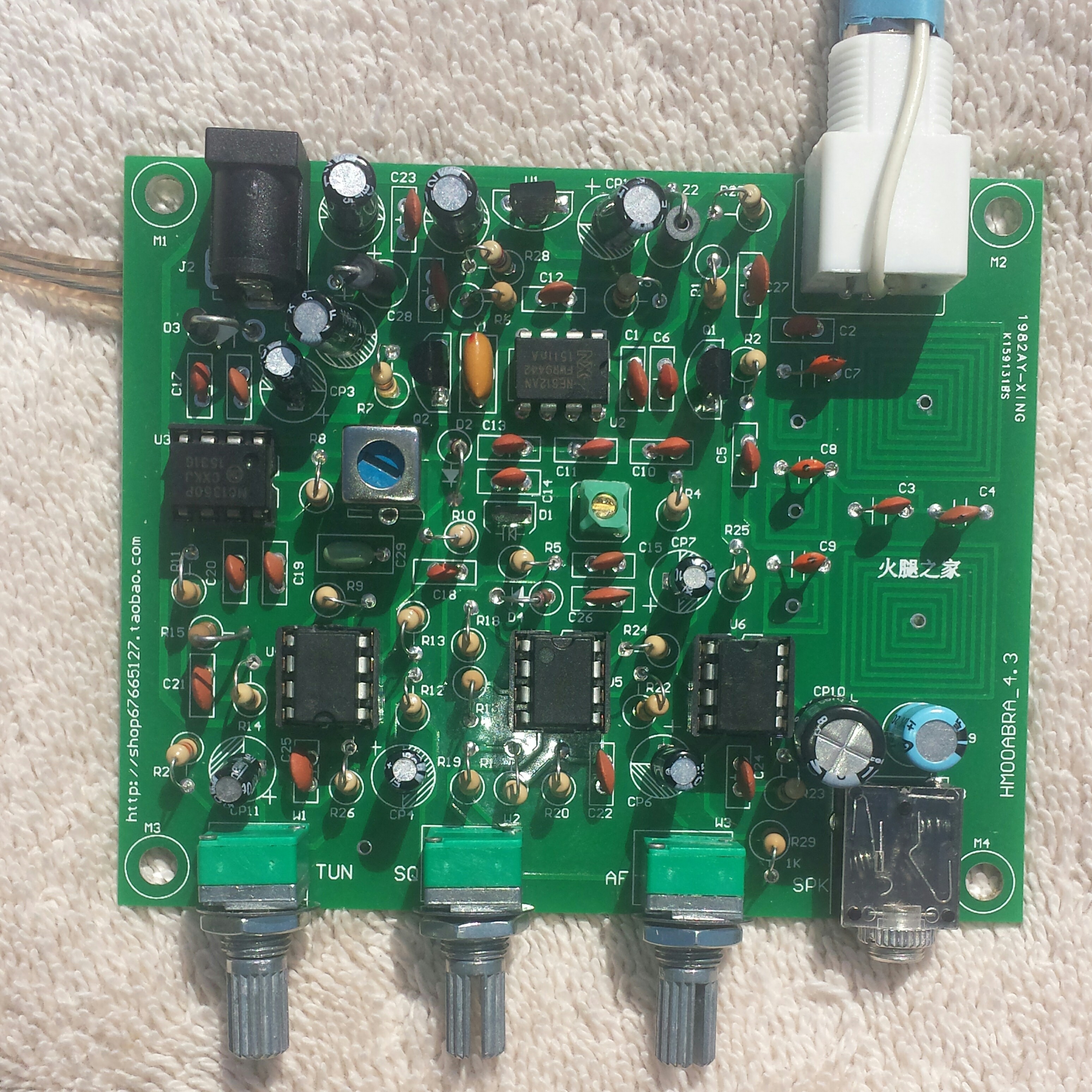
Receive frequency? I can’t receive a signal, so the receive frequency is not known. This receiver has no tuned circuit in the RF side of the NE612, other than the bandpass filter made up of the coils on the PCB and their capacitors. The bandpass is supposed to be 118 to 136 MHz, but as I said before, the dipmeter shows the coils dipping above the 2M band, somewhere near 200 MHz. However that may be caused by interactions between the filter elements.

I have measured the LO oscillating over the full range of the tuning pot, up to 158 MHz. But this is what seems odd. With squelch at minimum I put the DMM on the tuning pot wiper and get the tuning voltage from 1.85 at min to 8V at max. At 1.85V I hear hiss, and it peaks at 3.5V. But above 4V it falls off to silence.

Bob Johansen
Yeah the funny part is I can’t hear any FM stations either through the front end filter or bypassing the filter. I have heard an occasional change in the noise level, like one would get if a very weak signal was buried in the noise. But then I’ve heard a lowering in the noise level when I touched the tip of metal screwdriver to some parts near the LO, and the change stays after I remove the tip. I also noticed the same effect when I touched the brass slug with the tip of the screwdriver but not with a nylon tuning wand. I thought that it might be caused by wear on the coil by the slug, but when I removed the slug to see, it wasn’t touching the coil.

I can get noise and hum when I touch the tip to Out A, pin 4, so the 10.7 MHz side is sensitive. It seems that the NE612 is where the signal isn’t getting through. So I ordered some NE612 chips on eBay, they are stocked in the US even though the seller is in China. The chips should be arriving in a week. I may remove the chip and install the socket and try the SA602 from the Vectronics receiver just to see if it’s a bad chip.

BTW I measured the supply current, it was about 50 mA dead silent, and up to 70 mA when very noisy. The 78L08 gets quite warm.

Update 2021 Jan 27 – I did receive the NE612 and replaced it and the receiver then began working properly.  This chip is not supposed to be sensitive to static or whatever, so I guess it was defective from the factory.

default

2018-10-07 Air Band Radio Kit HMOOABRA_4.3 Part 4

default

2018-10-07 Air Band Radio Kit HMOOABRA_4.3 Part 3

From FB group Building Transistor Radios comment 2018-10-07

Bob Johansen
I don’t have a way of calibrating an RF signal level. Back when I worked on Aircraft radios we had General Radio VHF signal generators, attenuators and RF signal strength meters and a Panoramic spectrum analyzer. This would have been a piece of cake to t/s. Right now I’m thinking about unsoldering the NE612 and putting the socket in, and borrowing the NE602 from the Vectronics kit I built last month. I’m getting good sensitivity at the pin 4, IF output of the NE, but not good sensitivity at the RF input to the Q1 RF amp. All the voltages look normal at Q1. I may pull out the parts and Q1, I think I have all of them on hand, even a 2SC3355. I’ve been occupied with some other real life things that have priority right now.

© RustyBolt.Info/wordpress
CyberChimps