


Posted to FB group Building Transistor Radios 2018-10-06
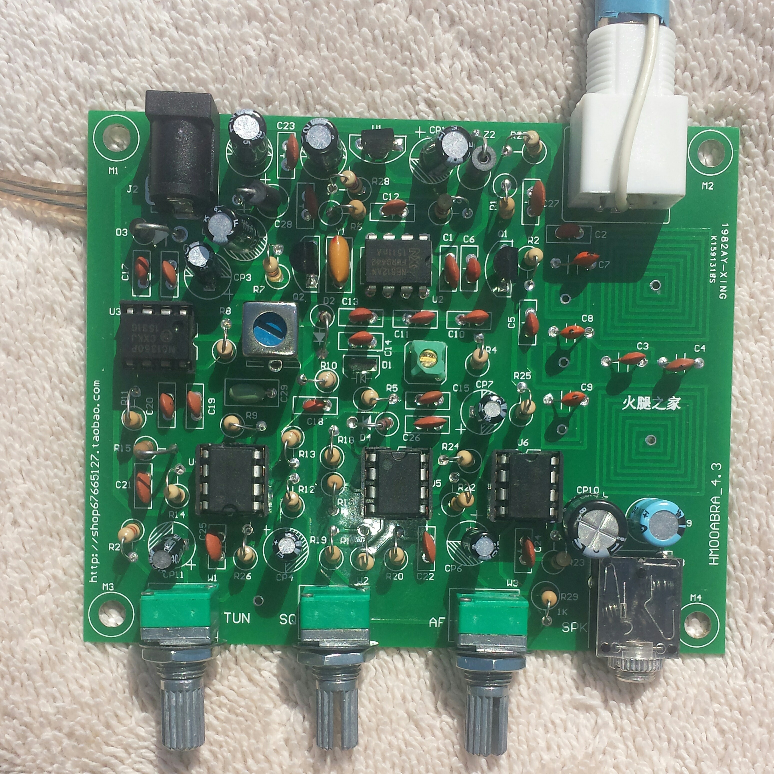
I noticed that my photo didn’t get added to the photos tab, So I’m trying again to add it.
I got a fresh start this Sat. morning. I used another little air band receiver to listen for the LO from this one. I turned the tuning pot to minimum which should be 118.00 MHz. I then set the other receiver to 118 + 10.7 or 128.7 MHz. I used a nylon tuning wand to tune the LO coil’s brass slug until I heard the LO fully quiet at 128.7. The speaker has hiss at this setting.
I then set the little receiver for 130, 132, 134, 136, and 138.0 MHz (highest it would go), and each time I could hear the LO in the little receiver as I advanced the tune pot. So the LO is oscillating all the way up to 138. But with the brass slug out most of the way, as soon as I tuned to 130, the hiss from the speaker went down to nothing and stayed quiet for all the other frequencies, too. This is puzzling.
I could hear transmissions on some frequencies in the little receiver. There is activity in the band. This little receiver uses a pair of ear buds for listening, and the antenna is the wires of the ear buds. So the transmissions have plenty of strength to be heard on a short lengths of wire, which is what I’m using for this receiver. But I have heard nothing but hiss on this receiver or no hiss, wherever I have tuned it.
I’m even more puzzled.
Update late afternoon – I forgot I had my Gy560 frequency counter in the drawer. I pulled it out and I touched its antenna to the slug and it gave me a reading. With the tune pot at minimum I set the slug for 118 + 10.7 or 128.7 MHz. As I tuned the pot, I could see the LO frequency go up and up. It should go as high as 136 + 10.7 or 146.7 MHz. But it kept going higher, all the way up to 158.7 MHz. That’s okay, but I would rather have the pot have a smaller range with greater resolution. So I’ll have to change the resistors to get the right range. But first I have to get it to receive a signal.
One thing that bothered me was the PCB coils dipping as high as 200 MHz. So I removed one leg of the C5 DC blocking capacitor, and I soldered a tiny switch to the leg so I can choose to have the antenna signal go through the coils on the PCB or bypass the coils and go directly to Q1. I tried a short length of antenna into the Q1 and it still does not receive any signals across the band. But I can hear the strong signal from my dipmeter at two places on the band, one below and one above the LO frequency, so it seems to be receiving very strong signals.


i had no time to wast, decided to set fire to myn.
Hello,
I would like a wiring diagram for this receiver.
Best regards
U.Koehler
This is made by a company. You have to get all information from them.
See this link and check the pdf manual (https://n5dux.com/ham/kits/Airband-Receiver/).
This link gives “404 not found” error message.