default

2012-09-29 A 100 mV or 1/10 Volt Joule Thief

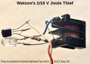
I made this JT with a transformer I pulled out of an old switch mode power supply from a PC (see the first photo).  The upper coil had a single turn as it came from the PS, so I removed that and wound 15 turns of 26 AWG enameled wire on the bobbin.  Its inductance was somewhat more than 100 uH, and the turns ratio of it and the other (bottom) winding was about 1 to 5.  The upper winding became the primary (connected to the collector).  The transistor was a BC337-40, and the resistor was a 220 ohm 1/4 watt.  The LED was a yellow superbright.

The LED was connected anode to the collector and cathode (flat spot) connected to the base. This takes advantage of the greatest difference of potential when the transistor shuts off.

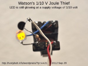
The second photo shows the LED glowing with 100 millivolts or 1/10 volt from the supply.  The LED is still glowing, though weakly.  The circuit starts at 0.408 volt, and will still keep running below 100 mV, but the LED will be very dim.  The frequency was 3 kHz.

The supply current at 1/4 volt was 46 mA, and at 1/2 volt was 96 mA.  I think this circuit would make a good converter for a single solar cell that puts out 1/2 volt.  But the 220 ohm resistor will have to be adjusted to accommodate the current output of the particular cell that is being used.  The idea is to have the circuit put the optimum load on the cell when it’s putting out at its best.

Back to experimenting…

default

2012-09-28 Photo Of Supercharged Joule Thiefs

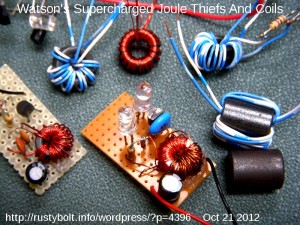
A picture of my Supercharged Joule Thiefs and some coils I wound.

I noticed that the LED in the center has a big bubble in the lens.  I got some LEDs with bubbles in them from a seller on eBay, and I had to send them back to get a refund.  I think this must have been a different seller.

default

2012-09-27 Bought A Joule Thief At The Store Today

on September 27th, 2012 by - Comments Off on 2012-09-27 Bought A Joule Thief At The Store Today

I bought a Joule Thief at the store today.  Well actually there’s more to it than just that.  Yesterday I stopped by Harbor Freight and bought a heat gun (that’s another story) and I saw something that caught my interest.  It was a battery tester for $2.50 that had three LEDs.  It tested two kinds of batteries; a 9V and a 1.5V battery.  It looked like this one, but with three LEDs instead of the meter.  It used the tested battery to power  the LEDs.  I could see testing the 9V, because all it needed was some resistors and the red, yellow and green LEDs.  But in order to test a 1.5v cell and light a 2 to 3 volt LED, it must have some kind of voltage boost circuit.

I got home and tested a few AA cells with it.  I was surprised how the LEDs switched on and off abruptly, no blending of any two colors.  And they were bright even though the AA cell was between 0.9 and 1.2 volts, which was the red “Replace” LED.  I was thinking about how they were getting this gadget to work at such a low voltage.  The only thing I could come up with was that it used a Joule Thief type of circuit to boost the voltage to run the circuit.  My curiosity got the best of me and I decided I had to open it up to see how it worked.  But I needed to use it to test more batteries and I didn’t want to damage it.  So I waited for today to buy another one to open up and examine.

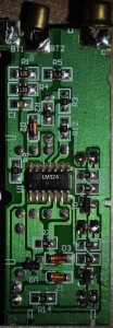
I managed to get a small screwdriver between the two halves of the case and pry it open gently.  It finally came apart revealing the circuit board.  The circuit was quite complicated for a device that was so simple externally, just three LEDs.  Most of the components were surface mount on the copper side of the board, but there were seven parts and three LEDs on the other side.  I found 2 transistors, a 33 microhenry choke, a 1N5819 Schottky rectifier,  a 47 uF capacitor and a BAP16 voltage regulator, which apparently made up the DC-DC voltage boost circuit.  The main circuit used a LM324, which is a quad opamp, but in this case is used as a window comparator.

There are two 12 ohm resistors and a ceramic capacitor across the 1.5V battery input, so there is a 250 milliamp load on the battery when a fresh 1.5V battery is connected.  The 9V input has a 470 ohm load resistor, so the load current is 19 milliamps.  However these values do not include the current needed to run the circuit and LEDs.

I haven’t had a chance to sit down and draw a schematic of what I saw, but if one googles for window comparator and/or battery tester they will come up with some circuits to give an idea of how it works.  One somewhat similar circuit is here, but in Czech, so you may want to use a translator to get a somewhat understandable version.

default

2012-09-26 Joule Thief Works With The 2N3904 Backwards

I was observing this video, and I saw that the 2N3904’s collector was connected to the negative and LED cathode, and the emitter was connected to the coil winding and LED anode.  But I was surprised that when he connected it up, the LED lit up.  Weird.  But when he tried it with the 2n2222A (probably a PN2222A) backwards, it would not light.  Which is what I had expected with the 2N3904.  Apparently the 2N3904 had enough gain in the reverse direction to oscillate.  But the emitter to base breakdown voltage is only 5 volts; fortunately the circuit stays below that maximum.

Back to observing others experimenting (scary!)…

Update Sep 28 – TK has come up with another 18 minute video which does further experiments with the transistors in forward and backward.   I like his test jig setup;  he has everything glued down to a piece of veneer board, and everything stays put so it’s easy to make changes.  However  he could eliminate the current monitoring gizmo between the battery and holder.  I think he has a double throw, center off switch.  It would be easy to mount two #4 screws on the board to allow clipping on his current monitoring meter.  Then switch the switch one way to monitor the current, the other way to bypass the current monitor.

The problem is that during his experiment, the voltage on the depleted AA cell is changing.  So it’s impossible to get an apples to apples comparison between the different configurations.  I noticed that at one point in his readings the battery voltage was down to 0.76 volt, which is so low that the JT would have a hard time oscillating with the transistor in the correct way.  I think it would be much better if he used a fresh battery with a stable 1.5 volts.  Also it is wise to put a 10 uF or 22 uF capacitor across the battery leads to help eliminate any tendency to be unstable.

Measuring power input is easy: just multiply the input voltage by the input current.   But how do you measure power out?  You put a 1 ohm resistor in series with the cathode of the LED.  Then measure the voltage across this with the DMM set on 200 millivolts.  Every millivolt will be equal to a milliamp, so 17 millivolts, for example will be 17 milliamps.  Then take .017 amp (same as 17 millliamps)  and multiply that by 3.3 volts, which is the assumed forward voltage of the white or blue LED.  This will give you .0561 watt or 56.1 milliwatts.  Divide that by the power in, then multiply by 100 to get the percent, and you have the efficiency.  My Supercharged Joule Thief   has an efficiency of 70 to 90 percent.  Since the 3.3 volts is assumed, this measurement is not entirely accurate , but it gives you a very good comparison of differences when you make a change to the circuit.  If you want absolute accuracy, you should measure with the LED held a fixed distance away from a light meter inside of a dark enclosure, to shield it from ambient light.  This will give you the actual light output.

Maybe I should build a test jig like this.

I had an earlier blog with the transistor in backwards.

Back to experimenting…

default

2012-09-25 Single Versus Two Transistor “Joule Thief”

I received a Google Alert with a link to this Instructable.  The author uses the two transistor, single winding voltage booster, often incorrectly called a Joule Thief, because he wanted to avoid having to wind the two winding coil.

The Joule Thief name was given to the single transistor, single resistor, two winding coil version. The two transistor voltage booster has been around a long time, and was never called a Joule Thief. Only recently have people been adding confusion by calling this and other V boosters Joule Thiefs just because they happen to light a LED similar to the conventional Joule thief.

It might be cheaper to use a single winding coil in a production environment – silicon is cheaper than copper.  But the experimenter can wind his own two winding coil using a toroid core from a dead CFL light for nearly free and a few minutes of his/her time.  I think it’s good practice for learning electronics assembly.

I’ve built many of both types and have found each has its advantages and disadvantages.  The conventional one transistor Joule thief is so much simpler that the neophyte can make it work almost all of the time.  The two transistor version has some gotchas when it comes to variations in the gain of the two transistors.  The circuit the author posted shows R1 as 1k, I’ve often seen it lower, 470 or even less.  And it is a good idea to put a resistor, maybe 1k, from Q2’s base to its emitter.  This helps to keep leakage current from Q1 collector from being amplified by Q2.  But it will work okay the way it is most of the time without any changes or improvements.

The conventional (single transistor) Joule Thief has a limitation that the supply voltage should never exceed 5 volts.  This assumes that the total voltage across the LEDs is more than the supply voltage (two LEDs in series adding up to 6 or more volts).  The voltage across the LEDs is also reflected in reverse across the feedback winding and hence across the base to emitter junction – it’s the same negative voltage, assuming the windings are the same number of turns.  This voltage must never be more than negative 5V (for most transistors).  If the voltage is higher, then the emitter to base junction goes into breakdown and the transistor is damaged.

In either circuit, you should use the DMM on ohms range to measure the resistance of the coil winding that connects to the collector.  The resistance should not be more than a quarter of an ohm.  But some DMMs use test leads that are so cheap that when you short the probe tips together, the meter says it’s a half ohm resistance, or maybe even more.  So you have to guesstimate what 1/4 ohm is.

The efficiency of the conventional Joule Thief is about 40 to 70 percent, typically 50%.  I’ve measured this on several examples.  The efficiency of the two transistor “JT” is somewhat similar.  I have done a few measurements and found nothing notable about this circuit.  But then that is to be expected when either is compared to my SJT, which has an efficiency of over 70%.

Back to experimenting…

default

2012-09-24 LED Tester Uses Joule Thief

A  few years ago I made a LED tester that used a 9V wall wart, a 5V zener for a shunt regulator, and three 100 ohm resistors to limit the LED current – one resistor for each LED socket.  The problem with this was that it was plugged in all the time and since it was shunt regulated, it wasted power all the time.  Even without the regulator, the wall wart itself wastes a few watts just being plugged in.  So I decided to go greener and eliminate the waste of electric power from the wall, and instead use a battery to test LEDs.

I built this germanium Joule Thief on a small piece of thin veneer plywood; it smelled like cedar when I cut it.  I drilled the holes with a pin vise and a small drill, might have been 1/16 inch diameter.  The germanium transistor is a 2N525, made by ETCO.  This company went out of business back in the early days, so if someone knows the date of their demise, it would be a good date to state that this transistor was at least that old –  my guess is early 1960s.

I got the toroid core out of a dead CFL light.  Each winding is 122 microhenrys.  There are three windings, one wound by itself and the other two wound bifilar.  I connected the two bifilar  windings together in parallel.  The wire I used was 30 AWG or .25 mm.

The resistor was 1000 ohms.  The 2N525 is PNP so the battery positive is connected to the common and emitter.  Therefore the pulses at the collector are more negative, therefore the 1N4148 diode must have its cathode tied to the collector, and its anode connected to the negative lead of the 10 uF electrolytic capacitor.  The positive of the capacitor was connected to the positive common.

Then I connected two yellow LEDs in series and connected both across the 10uF capacitor.  These yellow LEDs act as a voltage limiter, and start conducting when the voltage across them gets to negative 4 volts – MOST LEDs have a maximum of 5V in the reverse direction.  For testing, I connected two wires across the capacitor.  If any type of LED is connected to those coiled wires, it will light up and all of the current will go through the LED, and the two yellow LEDs will no longer conduct and will go dark.  All of the current that was going through the yellow LEDs will be diverted through the single LED connected to the coiled wires.

I haven’t yet soldered alligator clips to these coiled leads.  I think that it also needs an On/Off switch, but the battery ‘holder’ is easily disconnected from the battery, so maybe not.  Update: I added an On/Off switch under the green coiled wire.   I also added a spring clamp to the underside of the board, which is one end of a metal battery holder with the contact removed.  It grips the middle of the battery firmly, so it will not fall out.

Another idea I thought of was to add automatic shutoff, but I don’t think it would work on a battery that is below a half volt – as it is. it will work down to 1/4 volt or even less.

The circuit draws about 40 milliamps from a 1.5V supply.  The frequency is about 95 kHz.

Back to experimenting…

default

2012-09-23 The Importance of Bypass Capacitors

on September 23rd, 2012 by - Comments Off on 2012-09-23 The Importance of Bypass Capacitors

Sometimes the circuit works all the time without a bypass capacitor.  Sometimes it works most of the time without a bypass capacitor.  Sometimes it doesn’t work at all without a bypass capacitor.

As you can see, this chip didn’t have a bypass capacitor when the PC board was originally designed.  Apparently the chip worked but had some problem which was cured by putting a bypass capacitor across the power leads later when the board was reworked.  Bypass capacitors can make all the difference between a circuit that works and one that has a mysterious and elusive problem every so often.

I bought a kit of a “Dice Roll” circuit.  It used a 555 timer chip and ran off a 9V battery.  I noticed when I assembled it that there was no bypass capacitor across the power leads.  I decided to try rolling the dice to see if the circuit was giving the same odds that a normal single die would give.  It was off considerably.

I put a bypass capacitor across the power lines and tried it again, and the problem went away, the circuit behaved as it should have.  Lesson learned.

Conclusion – The hardly ever noticed bypass capacitor is a very important part of the circuit; without it, the circuit may not function or function erratically.

default

2012-09-22 Germanium Joule Thief Squeezes The Energizer Bunny

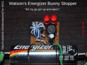
Here is my latest germanium Joule Thief, shown squeezing the last few hundred millivolts out of the Energizer Bunny (“It just keep going and going…”).  This is a real Zombie Battery Killer – that last half volt left after the regular silicon JT has given up is now sucked out, down to less than0.2V.    This one uses a General  Electric 2N525, most likely made in the early 1960s.  G.E. was a big manufacturer of semiconductors, but left to manufacture the appliances such as the Toaster Ovens and coffee makers we’re all too familiar with, and jet engines.  I still have one of their gigantic copper oxide rectifier stacks which looks like a selenium rectifier stack only the plates are round, not square.  And I have several thousand of the GE 2N5172 transistors, which are still available today from other manufacturers.  The G.E. Transistor Manual, 7th Ed. (1967) was the bible for any engineer or tech working with solid state components.  But today, most germanium parts are made by plants in eastern European countries and have been almost totally replaced by silicon in modern equipment.

I have been measuring the AA cells after they have been drained by the germanium Joule Thiefs, and the cells measure less than 200 millivolts, some as low as 150 mV.  When disconnected, they will recover some voltage, but they are much more lifeless than when they were on a silicon Joule Thief.

Back to experimenting…


default

2012-09-21 Very Low Inductance Joule Thief

In an earlier blog a commenter asked asked a question about how much inductance a Joule Thief should have; is there too much or too little.  Well, I assembled and experimented with this Joule Thief to find out how little was too little.

I cut of two 16 inch (40 cm) lengths of 30 AWG (.25mm) magnet wire and wound them bifilar around a short length of 1/4 inch (6.35mm) diameter soda straw.  Then I put adhesive tape around it to hold the wire in place.  I tinned the wire ends with the soldering iron (this enameled wire insulation is the kind that melts with a soldering iron).  I measured the inductance at 1.38 microhenry, which is extremely low for a Joule Thief.

I connected it to a conventional Joule Thief with a PN2222A transistor, white LED and a thousand ohm resistor.  I knew when I connected the wires that I was connecting them with the correct polarity.  But when I applied the 1.5VDC, the LED did not light up.  It kind of flickered once in awhile when I touched the alligator clip to the cell’s contact.

I knew that the JT was going to be switching at a very high frequency with a coil with such a low inductance.  I figured that the transistor might not have enough gain at this high speed, and that I might help it to oscillate by putting a small value capacitor across the resistor.  I soldered a 100 pF ceramic disc capacitor across the resistor.

I powered it up and the LED lit up.  But less than a minute later, the LED went out.  I disconnected the power, visually examined the wires to see if there might be a loose connection but found nothing wrong.  I reconnected it and the LED lit up, but it again went out less than a minute later.  Weird.  I put my fingers on the transistor and it was warm.  Hmm, it seemed to be overheating and quitting soon after power was applied.  That’s very interesting.

I disconnected it and reduced the power supply down to 1.25 volts DC.  When I reconnected the circuit, it stayed lit, even though the transistor still felt a bit warm.  I connected my DMM set to the frequency range but the frequency was too high for it.  I got out my Heathkit GDO (actually a FET dip oscillator) and measured the frequency at 2.5 MHz.  Wow, that’s really high!

The reason that the circuit wouldn’t oscillate without the 100 pF capacitor is simple.  The transistor has an input capacitance of up to 25 pF.  At 2.5 MHz, 25 pF has a reactance of about 2540 ohms.  So the 1k and this capacitive reactance make a low pass filter that attenuates the signal coming through the resistor.  The 100 pF lets enough of the signal bypass the resistor and go to the base, so the transistor can sustain oscillation.

Another factor is the Miller capacitance, or the capacitance between the collector and base.  At high frequencies this capacitance causes negative feedback to the base and reduces the gain.  Also another factor which becomes significant at high frequencies is the capacitance of the LED.  This has to be charged each time it is switched on, so it becomes a significant part of the load on the transistor.

So the transistor was getting really hot inside and overheating when the power was 1.5 volts.  Apparently the time that the transistor takes to switch on and off was a large percentage of the time during each very short switching cycle, and the transistor wastes a lot of power and overheats.  Each switching cycle is 1 / 2.5 MHz, or 400 ns (nanoseconds). The datasheet for the PN2222A shows a risetime of 25 ns and a fall time of 60 ns.  These are a significant part of the switching time, and during these times the transistor is not saturated or cutoff, so the transistor is dissipating power.  The storage time, which is the time it takes for the transistor to come out of saturation, is also important.  For the PN2222A, this is as much as 225 ns, over half of the switching time, which is 400 ns.  What this all adds up to is that the transistor is huffing and puffing as it tries to keep up with the high switching frequency.  The answer to the question I asked is this coil has too little inductance.  I need to increase the coil windings and inductance so that the circuit will oscillate at a much lower frequency, such as 1/10 of 2.5 MHz or 250 kHz, or even less.  The transistor will then waste much less power, and the circuit will be more efficient.

As would be expected, increasing the coil inductance will reduce the frequency, which is clearly too high in this case.  To reduce the frequency to 1/10, the inductance will have to be increased by more than ten times, and from previous Joule Thief designs, it looks like increasing it to 100 microhenrys is a good estimate.  The thin 30 AWG wire will have too much resistance, so heavier wire will have to be used.

Back to experimenting…

default

2012-09-20 Supercharged High Efficiency Joule Thief

The photo is of one of my Supercharged Joule Thief circuits that I built a few years ago (see link at the end). This one has a supply current of 70 mA at 1.5V and a LED current of 25 mA at 3.3V (actually 25 millivolts measured across the 1 ohm [2 resistors] in series with the LED’s green wire). This calculates to an efficiency of 78.6 percent. The frequency is 250 kHz.

The circuit is almost as simple as the conventional Joule Thief; it requires a diode and 680 pF capacitor in addition to the 1k resistor. The end of the feedback winding that was normally connected to positive is instead connected to the 1k and 680 pF as shown in the picture. I used a SS8050 transistor, which is a Fairchild equivalent to the C8050. It can handle up to 1.5 amp collector current, More at fairchildsemi.com and search for SS8050. Note: Fairchild Semi is now a part of Onsemi.com.

The circuit will give more LED current for about the same supply current, or the resistor can be increased to 1.5k to give about the same LED current for less supply current. The two current sensing resistors that are in parallel on the lower right are optional and can be removed, and the LED’s green wire connected directly to the heavy negative wire.

More information and a comparison can be found in my earlier blog.

© RustyBolt.Info/wordpress
CyberChimps