


I walked into the office and I found two of the guys trying to make one of these free energy fans with a fan from a PC and four powerful magnets from hard disk drives. He showed me the Youtube video, so I went back later and watched it again. They couldn’t get it to work. “Sure,” I told them, “I can get it to work”. Then I revealed the secret. The guy in the picture has an air blower or vacuum cleaner hose beside the camera pointed at the fan. When he puts the magnets on, he turns on the air, and the blades spin. Simple as that. There are no visible signs of any cheating, because you can’t see air blowing – it’s invisible!

2012-10-13 1960s Flasher for Light Bulbs – BD433 Modified
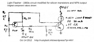 I continued on with my experiments using the BD433 by building a Light Flasher. This flasher is a very old design which originally used germanium transistors. It also predates LEDs, so it used a standard #1850 miniature lamp or incandescent light bulb. Instead I used LEDs, so I had to allow a small current to bypass the LED during the off time, to prevent the LED from glowing dimly. I did this by putting a 4.7k resistor R6 across the LED.
Also, because the original used germanium transistors, which are lower gain and somewhat leaky, the resistances were lower than needed for silicon transistors. So I changed R1 and R2 to ten times their original values, 47k and 82k. I increased R3 from 3k to 33k, and decreased C1 from 250 uF to 22 uF. R4 stayed about the same, 82 ohms. R5 was originally 820 ohms because the germanium transistors tend to be leaky and this low resistance minimized the base current leakage. But a silicon transistor would probably work just fine without it, so instead, I put a 22k there. Any resistor from 1k to infinity may work without problems. As I said, R6 across the LEDs was 4.7k. For Q1 I used a 2N4403, and for Q2 I used the new BD433 transistor I just bought.
I built the circuit on a postage stamp sized piece of perfboard. The BD433 is conducting high current, but is fully on or off almost all of the time, so it does not get warm. But the current is very high; the power supply I used was capable of supplying 1 amp, but the voltage dipped with each flash, indicating that it was going into current limiting. I set the power supply to 5V, even though it originally used 6V. I connected up the LED assembly from a 9 white LED flashlight from the 99 cent store, and also a green 1 watt Luxeon Star LED in parallel. Even though the forward voltages of these two are very different, they both light up very brightly because the current is so high that the peak voltage drop across the green LED is more than 3.3V, and part of the current then goes through the white LEDs.
The flash rate was about 1.4 Hz, or ten flashes every seven seconds. The project was successful the first time I powered it up. The BD433 makes a very good choice; it handles the very high current pulses easily.
Other thoughts – It might help if there was a 10 000 microfarad bypass capacitor across the supply at the point where the leads are on the perfboard. this should reduce the very high peak current the power supply has to supply. The 1.4 flashes per second that it has right now is a good speed, and does not have to be modified. However the 33k resistor could be replaced with a 10k resistor in series with a 50k variable resistor AKA trimmer, so the flash rate can be adjusted. The pulse rate is short, and this flasher with only the white LEDs would make a good stroboscope if the speed was adjustable. It could be used to freeze motion, of a rotating wheel for example. Another cool thing to do is to have it illuminate someone with flashes while they go through motions, I’d guess this would be called multiple exposures.
An advantage of this design is that the flasher circuit is totally contained between the two wires, and requires only a connection to the light bulb and to ground or negative. This simplifies the wiring.
For much higher power, this circuit could be connected to a relay (put a 1N4003 across the relay, cathode to positive). The relay contacts then could control a very high current or high voltage. The relay would have to have fast acting contacts because the pulses are short. The more I think about it, the less I like this relay idea. First off, the relay may be too slow. Then there’s the constant clicking of the relay. And one has to consider how long the contacts will last when they are constantly turned on and off. All together, I think I’d skip the relay idea and instead use a high current transistor or MOSFET on a heatsink instead.
My blog with a schematic of another light bulb flasher.
Back to experimenting…


2012-10-12 BD433 And BD438 Transistors
I ordered some parts from Mouser, and along with them I ordered some BD433 and BD438 transistors. Belza uses the BD433 in some of his LED projects and as far as I can make out using google translate, Belza says the BD433 is supposed to do a very good job in a Joule Thief. The specs say it’s capable of handling 4 amps.
I built up a conventional JT using the BD433, and I added a third winding to the coil. The core is a Fair-Rite 26723002402. It’s trifilar wound with three lengths, each a foot and a half (45 cm) long, of 30 AWG enameled wire. The third winding is two additional lengths of 30 AWG in parallel. The third winding is the output of this coil and is rectified by a 1N5817 and filtered by a 47 uF ‘lytic, and then goes through the LED and a 1 ohm resistor to allow measuring the current. The LED is a 10mm 1watt single chip white; it can handle a few hundred mA.
The third winding is polarity sensitive; connection gives a brighter LED one way and dimmer the other way. The supply current was 120mA, the LED current was 22.5mA and the frequency was 10.5kHz. The BD433 in this JT is putting out more current than what would be typical for a BC337-25 or similar transistor.
Next JT – I used a core from a dead CFL and wound 2 windings, each 9 turns of 24 AWG, and measured the inductance of each winding at 101 uH. I connected another BD433 to it in the conventional JT circuit, with the usual 100 ohm resistor. I used a red 1 watt Seoul Semi ‘star’ LED. I connected this JT to the power supply set at 1.5V, and the LED would go on at the moment of connection, but it wouldn’t stay lit. I turned the power supply down to 1.2V and it worked okay, lit up brightly. I varied the voltage, and found that the LED got brightest at 1.1V, but got dimmer below that (as would be expected), and dimmer above that voltage (I didn’t expect that). At 1.1V the current was over 120 mA. Above 1.1V the current increased even though the LED got dimmer. I think the toroid core was having a problem handling all that current.
I unsoldered the core and soldered in a different core. This one had 6 uH and 6 turns of 24 AWG phone wire for the primary and 2000 uH and unknown but more than 20 turns of wire for the feedback wire. The LED lit up easily and very brightly at 1.5V, and the current was 250 mA.
I still haven’t opened the bag of BD438 PNP transistors. Back to experimenting…
2012-10-11 Finding An Equivalent Substitute Transistor
I came across this forum thread where the person asks how to find and equivalent transistor. First off I would like to say that if you substitute another transistor and it burns up in a few seconds, like it did in this case, then you should certainly consider that the circuit is bad in some other way and no matter how exact the replacement is, it is not going to work until the problem is fixed.
I faced this ‘sub’ question many, many times years ago when I did a lot more TV and receiver and audio repair, and found out how important it was to get the right transistor. Someone gave me a good quality stereo amplifier, and said he didn’t want it anymore because he had it repaired but it sounded awful. I put the ‘scope on the output and I found that it was oscillating at 2 MHz! If I had put a hundred feet of wire on the output, I could have had a transmitter!
I learned a lot about what the transistor datasheet is and how to use it. The manufacturers used to publish a data book, and they gave them away freely for just asking in a letter with you company name (a friend and I made up the company name Solid State Systems). So I got many transistor manuals and data books for every type of electronic component.
Nowadays, much of the data cane be found online by googling for 2N3055 datasheet for example. You will get many hits for places that will let you download the datasheet .PDF for free, as long as you look at all their annoying adverts.
But then what do you do with this datasheet? It’s full of technical jargon that the average person doesn’t understand. It took me years to learn enough about this to make a good judgment on what’s important to know in order to make a correct substitute.
In this forum thread, people give all sorts of advice, from good to totally incorrect. I once told someone that his advice was, to be tactful, less than accurate, and you know what he told me? “The advice you get is worth exactly what you paid for it! $00.00!” And he was right. If you get free advice, you can expect that it’s worthless!
But I try to give worthwhile advice. Not many care, though. They have no clue as to whose advice they should take. As a result they go wrong and are very often discouraged enough to throw the device out and go buy another new one. I think if more people would try to repair the broken equipment, it would save a lot of resources and the world would be a better place. But that’s a discussion for another time.
Back to transistors. in the case I cited, he could get replacement 8050 transistors from Mouser or Fairchild, called the SS8050. They are very cheap, maybe a nickle apiece, even less in quantity. But the shipping might be many times the cost of the part.
There is another part that might work. NTE sells replacement parts at ten or more times the cost from a distributor. They sell the NTE11, which is a very high current transistor, for about a dollar fifty. It’s in the same package as the 8050. But the gotcha is that the pinout is E C B instead of the 8050’s E B C – it’s the same as other similar Japanese transistors. So you will have to slip a short length of insulation (stripped off a solid wire) over the collector lead so you can cross it over without it shorting against one of the other leads.
There are other substitutes, but those two are readily available. You can go to Radio Shack and buy some transistors from them, but the salesdroids don’t know any more about substitution than their customers, so buying a transistor from them is most likely hit-and-miss and a waste of time and money.
Substitution in General – I have a few publications that are my favorite references when it comes to substitution. I used the National Transistor Databook so much that I wore it out, and had to get a replacement on eBay or Amazon, I forget which. The great thing about this book is that it tells you which process the transistor came from. Then you can read about that process, find out what the chip looks like, and find which other transistors use the same process. For instance, you might find that the 2N4124 uses a certain process, and 2N3904 comes from the same process. So if the circuit demands are modest and the packages are the same, then one transistor could be substituted for the other.
Motorola Transistor and Diode Manual – This tome (it’s 3 inches thick!) was the reference for just about any U.S. transistor or diode made up until its publication in 1969. This still covers a lot of the devices used today. After that there was not so much growth in the number of discrete devices (transistors, diodes, etc.) and more growth in integrated circuits. Today the number of transistors registered with the 1N and 2N numbers is still under ten thousand. There are other transistor makers that published transistor manuals and crossreference manuals, one was Sylvania, AKA ECG.
NTE – Another way to get a rough idea of a substitute is to use the NTE catalog. You can also go online and search their web pages. Having the catalog on paper is easier and faster. There is one gotcha. I have done lookups in the NTE catalog, and they seem to think that the NTE123A or NTE123AP will substitute for just about any small transistor, when I know that they will clearly not substitute. But the catalog will give the reader a good idea of what package their substitute transistors are in, and what their rating are. For instance if the transistor is a power transistor, you can find the package and how much power, etc. it will handle. NTE sells a line of replacement transistors and parts, but their prices are very high. If you have an immediate need for a single part, then they may be a worthwhile solution. But I find that it’s much cheaper to buy a bag of a hundred transistors from Mouser, DigiKey, etc., for the price of one or a few NTE transistors. The NTE numbers are the same as the Sylvania ECG numbers, so NTE123AP is the same as ECG123AP.
There was a lot of growth in the Japanese (2S numbers) and the Pro Electron (AC, BC, BD etc. numbers) series. These were used in a lot of the equipment manufactured in Japan, Europe and other overseas countries. Very many of, or possibly most of consumer electronics equipment has Japanese numbered parts. These numbers usually start with 2SA, 2SB, 2SC, or 2SD, however the transistor package has so little room that the numbers are usually abbreviated by dropping the 2S. For instance the 2SC1815 transistor is marked C1815. So if you look up the substitute for C1815, also look up the sub for 2SC1815. Similarly, sometimes the European makers dropped the B, so a BC547 transistor may have C547 on the package. The BC547 number is one of the Pro Electron number series, which originally started with A when the transistors were germanium. Now most transistors are silicon, which starts with a B.
Many transistors have numbers similar to the JEDEC 2N numbers. One good example is the 2N2222A, which comes in a metal package. Manufacturers used the same chip in a different plastic package to make them much cheaper, and gave them a similar name such as MPS2222A or PN2222A. Also, the same transistor chips can be found in surface mount packages such as PZT2222A or MMBT2222A. There are also integrated circuits that have four transistors, such as the MPQ2222A, which may be very difficult to find. So if there is room, four individual PN2222A transistors could be used.
Circuit Design – I should also discuss circuit design. In the early years of transistorized equipment, the cost of the transistor was higher and designers tended to design equipment with few transistors. The ultimate transistor radio “reflex” receiver used a single transistor for first amplifying the radio frequencies, then after detection, the audio was fed back through and amplified by the same transistor! Consumer equipment used coils and capacitors for tuned circuits, and these had to be adjusted or “aligned” at the factory for proper operation. At one point the makers started using “SAW” filters which did not require alignment, and this elimination of labor saved a lot of money and time. So designs became more complex as automation made assembly much cheaper and less dependent on labor. The result is that if you are replacing the transistor in older equipment, the substitute most likely needs to be more compatible, because it is likely that the equipment will have to be re-aligned. More modern equipment may be much more tolerant of transistors that are not as close a substitute.
Back to experimenting;…
2012-10-10 Substandard Power Cord Is Fire Hazard
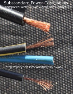 I bought a PATA/SATA to USB adapter that consists of the adapter, an AC power brick and assorted cables, including the power cord from the power brick to the wall outlet. This world standard power cord is just like the ones on PCs, monitors, printers, etc., but it’s short, about a meter long, But the most disturbing thing about it is the substandard wire used, This particular cord is marked 0.5mm2 along its length, but other cords I’ve seen don’t have any markings. This wire is about the equivalent of 24 AWG. It’s tiny compared to a standard lamp cord, shown in the picture. The plug is labeled 10A 250V, implying that the cord itself can handle 10 amps. I cut off the plug and connected the line and neutral wires together (the colors of the wires are also non-standard – ground wire is blue instead of the standard green). I then measurd the resistance of the cord from the wall plug, and got 1.2 ohms. This is many times higher resistance than a power cord using 18 AWG wire.
Let’s go through a scenario. The user leaves most of the cord bundled up with the wire tie around it. He then plugs it into a power strip and into a high current appliance, such as a big laser printer that draws 10 amps during the time the fuser element gets hot. The power cord’s 1.2 ohm resistance drops 12 volts at 10 amps. Power in watts is V times I, so 12V times 10 amps is 120 watts. What?!?! That means that the power cord will be dissipating so much power that it will overheat and catch fire! REALLY!
I’m not sure why this is being sold in the U.S, because it will not meet the long established electrical and fire standards. Could it be that this is sneaking through the system without being caught? Every American made product such as inexpensive lamps must use a power cord that meets standards.
2012-10-09 Watson’s 200 Volt Joule Thief
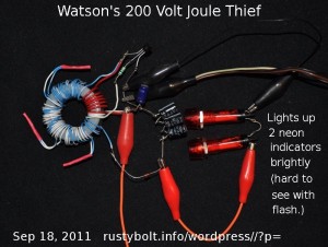 This is the photo from my watsonseblog dated about Sep 18, 2011. I don’t have the text. I may have it saved somewhere, if I can find it.
The toroid core was an ICH-ZJ43615TC from Surplus Sales. They most likely have sold out, but you can find the datasheet here.
Viewing the photo, one can count the primary and feedback windings. The secondary HV winding could probably be counted, but it really makes no difference; just add turns until the desired voltage is reached. Other than that, the rest of the circuit is just a regular JT. The rectifier was a BAV21 250V high speed diode, but the peak to peak voltage was probably higher than 250V. I should’ve used a UF4007 or put two or three BAV21s in series.
I see the cold end of the HV secondary is tied to the primary and collector for added voltage. I could have used a voltage doubler with two diodes and two filter caps. I had to put three 63v capacitors in series to get enough voltage. It was probably close to exceeding those, too. If you use some larger HV caps. remember that the voltage can be hazardous or lethal, so be careful.
2012-10-08 Coils and Toroids from BG Micro
I wanted to get some 100 microhenry chokes to experiment with, so I ordered a bunch from BG Micro. Also, I found they had some Steward 2B0686-100 EMI Suppression Filter, which once I cut through all the gobbledygook, came down to toroid cores. So I ordered a dozen or so of those. Then I found they had Dual Coils on Ferrite, so I ordered some of those. They quickly shipped the order and they refunded 3 bucks by shipping them by USPS.
Toroid Cores – . I should point out that these cores are made to go over the cable from the PC to the monitor, printer or keyboard, etc. Typically these suppressor sleeves are high permeability, several thousand. I opened up the package today and got down to work. I took one of the toroid cores and put a short piece of wire through the core and measured the inductance at 1.58 uH. I wound 16 inches of 24 AWG telephone wire on it totaling ten turns, and measured the inductance at 152 uH. I took another core out of the bag and wound two lengths of the same wire bifilar again ten turns, and it measured 145 uH. The third and fourth cores wound the same way measured 142 and 145 uH respectively. I haven’t made a Joule Thief yet with one but I think these should make a good JT toroid
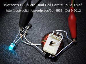 Dual Coils on Ferrite – I took one of the already wound coils out of the bag and measured the inductance. The green winding measured 1.91 mH, and the red winding measured 921 uH. I measured a second one and got 2.0 mH and 948 uH. The third one measured 1.98 mH and 951 uH, the fourth one measured 1.92 mH and 914 uH, and the fifth measured 1.85 mH and 889 uH. The BG Micro website’s page (link above) says the windings are 1.65 mH and 600 uH. I’m using an LC Meter IIb, which has an accuracy of 1 percent and really does measure chokes marked 100 uH right around that value, so I trust its measurements. The values I measured are close to the standard values of 2 mH and 1000 uH, so for those reasons I think that my measurements are more accurate than the ones given in the BG Micro web page. I measured one winding diameter at 0.024 inch, so I think the windings are wound with 23 or 24 AWG enameled wire.
I soldered together a Joule Thief (see photo) using a PN2222A transistor, 1k resistor, a blue-green LED, and the BG Micro dual coil ferrite core toroid. The circuit drew a respectable 82 mA at 1.5V supply voltage. I used the green winding for the primary and the red winding for the feedback winding. As can be seen, the LED lit up brightly.
I swapped the primary and feedback windings, just to see how well it would work. The supply current went up to 90 mA at 1.5V. The frequency was 5.4kHz. I turned the supply voltage down to see how well it would work, since the feedback winding had half again as many turns as the primary. The LED was still glowing at 0.35v, and extinguished at 0.32v. The LED came back on when the supply reached 0.48V. This means that it will make a good JT for really depleting the battery. I also noticed that there is enough room in the hole in the middle to wind another winding, but I haven’t tried it to find out how many turns it can hold.
I was in for a surprise – I then opened up the bag of 100uH chokes and measured one and was surprised when it measured 79.5 uH. I pulled another one out of the bag and it measured 77 uH. The third through 10th chokes also measured between 77 and 79.5 uH. The silver band means that the tolerance is ten percent so the inductance should be between 90 and 110 uH. But these are more than 20 percent too low!
I had pulled these out of the bag with no particular order and my conclusion is that all of the remaining chokes in the bag are also around that value. There are a few possibilities why these are not the correct value. One is that they are ‘culls’. In other words, they are left over after the ones that are within tolerance are picked out. Another possibility is that the 100 uH value marked on them is the wrong value; they should have been marked 82 uH which is the closest standard value. Of these possible scenarios, it seems to me that this mismarked value is the best answer. Why? Because all of the chokes I measured (and most likely all of the rest) were all tightly grouped around a certain value. If they had been culls, the values would be scattered widely. I contacted BG micro about this and find out how to get a refund or some resolution. I’m waiting for a reply.
I received a reply back. They said they measured some of the same part number and they all measured about 100 uH. They then asked if mine were marked brown, black, brown (they are), and suspect that my LC meter might be wrong. I pulled another ten chokes out of the bag and measured them, first with my LC IIb 1% meter, and then with the LCM from China, which seems to be 5 or 10 percent accurate. Both meters measured the ten chokes in the high 70 uH range. I then pulled five 100uH chokes from my parts bin and measured them with both meters, and they all measured close to 100 uH. I took pictures of both of the measurements and emailed them in my reply. Right now I’m thinking they must have not measured the right part, or else their meter is wrong. I’m waiting for their reply.
The reply came. It’s kind of weird. His AADE LC IIb (same as mine) measured all 20 chokes at an average of 76 uH. He then measured them with a Velleman DVM6243 and they measured 105 uH average. He then used a B&K circuit tester and the chokes measured just over 100 uH average. So he offered a few things, one was to give me my money back.
I’m thinking about this, and trying to come up with another way to test the chokes. I think there’s something else affecting the measurement. It could be that the meters are measuring too close to the self resonant frequency and this causes result to be low. I’m going to do some calculations and see if I can build a circuit that will oscillate with a known value of capacitance and I can the calculate the inductance from the frequency of oscillation.
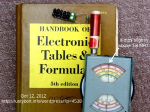 I changed my strategy (see the attached photo) – I eliminated any inductance meter that might influence the reading. Instead of building a circuit, I used my Heathkit Dip Meter. Not much here that can influence the resonant frequency. The dip meter doesn’t measure anything, it generates a frequency and when the coil is near a resonant circuit, the dip meter shows a drop in current when the variable capacitor is set to the resonant frequency.
I put five 470 pF silver mica capacitors in series, which gives 470/5 or 94 pF. These are precision 1 percent capacitors – they’re very accurate. I measured them and they measured 96 pF; the extra 2 pF came from the small circuit board and wiring. I put one of the chokes in parallel with this 96 pF capacitor.
I got my handbook of formulas and found the formula for resonance. Note: the inductance can also be found by going to this calculator and inserting the frequency and capacitance values and clicking on calculate. I used the handbook to calculate two resonance frequencies, one for 96 pF and 100 uH, which was 1,624,368 Hz or 1.624368 MHz. The other was for 96 pf and 78 uH, which was 1,839,235 Hz or 1.839235 MHz.
I then set the choke / capacitor resonant circuit next to the dip meter and adjusted the variable capacitor until the meter read a dip, indicating the resonant frequency. I got the dip when the variable capacitor’s dial read a bit above 1.8 MHz. This indicates without a doubt in my mind that the choke is 78 uH, since the dip frequency matches the frequency calculated for 78 uH. My conclusion is that all of these chokes are somehow labeled wrong and that I’m requesting a refund.
Update Nov 2 – The guy from BG Micro just sent me an email saying that he measured them with a different LC Meter IIb and with a HP network analyzer. The chokes measured 70 uH at low frequencies, but at 3.5 MHz, they measured 100 uH. I have a lot of confidence in the LC IIb at that 100 uH point, and I would bet my first born on the HP analyzer, since it’s definitely a class above the rest. So I have no doubts that they are giving correct values.
But the question is, what would be causing the chokes, which are marked 100 uH and 10 percent tolerance, to be so far off at low frequencies yet measure okay at 3.5 MHz? What kind of core material is frequency sensitive? Also, I’ve dealt with chokes at frequencies below and near self-resonance, and the inductance goes down as the frequency goes up toward self-resonance, not UP!
I can understand if you have a choke with DC going through the core and the magnetic field generated by the DC is causing the inductance to change. But to my knowledge these meters do not put any DC through the choke during measurement. This is some rather odd behavior that I have never seen before.
 Update Nov 15 – I tack soldered together a Colpitts oscillator consisting of one PN2222A transistor, a pair of 470 pF, 1% precision silver mica capacitors in series, giving 235 pF, and the BG Micro 100 uH choke, plus the resistors for bias and load. I measured the two capacitors without power and without the choke, and got 273 pF with my LC Meter IIb. This value is higher because the power is off, so I will instead use 245 pF (as the value for the two capacitors and the parasitic capacitance of the transistor and other components) when I do the following calculations.
The circuit oscillated in the middle of the AM broadcast band at 1130kHz – I used an AM radio to find the frequency. Using the formulas for resonant frequency, capacitance and inductance, I calculated the value for the BG Micro choke’s inductance at 80.97 uH. This is more than the 78 uH in previous measurements, but it’s still nowhere near the 100 uH plus or minus 10% allowable for the inductance that it is supposed to be.
To verify that my circuit and calculations were accurate, I got a 100 uH choke and put it in place of the BG micro choke. I found the RF carrier at 995 kHz, and I calculated the inductance at 104.4 uH. I measured the inductor at 104 uH before I installed it in the circuit, so my measurements and calculations agree fairly close with the measurement on the LC Meter IIb. This makes me feel confident that these measurements are reasonably accurate. Also, since all of the four measurements agree with each other, I’m confident in saying that the value of the BG Micro choke really is approximately 78 microhenrys plus or minus several percent.
Back to experimenting…
2012-10-06Lasersaber’s Joule Ringer V. 3.0
Lasersaber developed a DC to DC converter that drives a regular incandescent, CFL, LED and halogen bulb and runs off 12V. He calls it Joule Ringer V. 3.0.
In his video he tries out CFL, LED, halogen and incandescent light bulbs all with reasonably bright light. He powers it with a small 12V battery pack, I’m guessing NiCd, since it has to furnish a lot of current. But he tries it with a single AA cell and gets a dimly lit filament. You can see in the frozen video frame that it’s quite bright, which is surprising for a high wattage incandescent. He doesn’t say anything about how hot the 2N3055 gets, but it has no heatsink at all, which means that it must be getting warm. One advantage he pointed out is that the circuit shuts off when the bulb is removed. That means that the on/off switch for the lamp can serve as the on/off switch for the circuit.
The simplicity of the circuit is amazing, just a coil, transistor and light. And a battery, of course. This may be its Achilles heel, since there is nothing to limit the current. I don’t see a problem with putting an amp of current through the base to emitter junction in the forward direction, as long as it doesn’t exceed that too much. But the light might have a reverse current, and in this case it’s well over a hundred volts if the light is bright, If the incandescent light shorts, which it often does when in a regular lamp, then the emitter to base junction will be melted and the transistor will be dead. CFLs sometimes go bad; I’ve seen them with the transistors and chips blown apart from excessive current. If this happens in this circuit, it’s most likely the same thing will occur.
I think it I had it, I would put two 1N4003 diodes in series and then across the emitter to base, with the cathodes pointing towards the base. It might be a good idea to put another pair across these, only in the other direction. Then if the E-B or B-E voltage becomes excessive, the diodes will conduct and shunt the damaging current away from the junction.
But in all cases, this circuit is putting over a hundred volts across a 2N3055, which has a maximum voltage rating of 60V, and was never meant to handle anything higher than maybe 70 or 80 volts. There’s no neon light, no zener, no anything to protect the transistor from overvoltage. Why people don’t choose an appropriate high voltage transistor is a mystery to me. They’re free in all those old PC power supplies that people often have laying around. And they come with a free heatsink, too, and they’re already mounted on it. It’s so easy to just unsolder one or both and use them instead of burning out a whole bunch of 2N3055s.
I have boxes of 2N3055s, maybe I should try to make one of these to see how it works. But I won’t pay $30.00 for a ferrite bar. I may use one of those Big Old Toroids I got from BG Micro. At least the price is right.
I said DC to DC converter because the current going through the light also goes through the base to emitter junction of the transistor. This acts like a diode, through which current is supposed to go one way only. If the voltage gets excessive and the current goes through both ways, then the transistor is going to be damaged.
Back to experimenting…
2012-10-03 When Is A Joule Thief Not A Joule Thief?
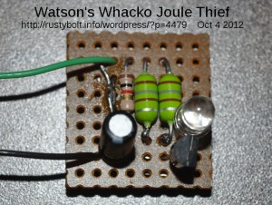 Well, I saw this way of emulating a coil in the Wikipedia entry for Joule Thief. I said to myself, this is really Mickey Mouse, and it would never withstand the scrutiny of an engineer or designer if they saw it. It’s just not the way a circuit should be designed. But I did it just to see how it worked.
What I did was put two 180 microhenry chokes (the green blobs) side-by-side so that the electromagnetic field from the choke connected to the collector is coupled through the air to the feedback choke connected to the base so that it generates enough current to keep the circuit oscillating. After I built it, the first time I powered it up it didn’t oscillate. I had to rewire one of the chokes – swap the wires – so that it was phased properly. The connections were originally with the top lead of one choke connected to the +1.5V, and the bottom of the other choke connected to +1.5V. But that was the wrong way, the tops of both chokes had to be connected to +1.5V for it to oscillate. Some of my resoldering can be seen in the photo.
The LED was a blue superbright LED. The transistor I used was an SS8050, which is capable of handling more than an amp of current. The supply current went above 110 milliamps and the LED became very bright when I turned the supply up to 1.5V; I thought that the current was excessive, and I turned down the supply to 1.25 volts, where the current was a more comfortable 75 milliamps. The current at 1.5V should be reduced by changing the resistor to a higher value; 1.5k or more would help. Or else use a much more common 2N4401 or PN2222A.
Also, the 180 uH chokes each have about a 2 ohm DC resistance. This is excessive, a better choice would be to use a 100 uH choke that has a DC resistance much less than 1 ohm, preferably 1/4 ohm or less. This only applies to the choke connected to the collector; the feedback choke doesn’t matter. Whatever choke is used, it must have an open core; the windings cannot be covered with anything that prevents the magnetic field from escaping. Without the external magnetic field, the circuit won’t work.
So the answer to how well it works is it works just fine. But I wouldn’t put it into service without covering the two chokes with a thick coating of silicone glue to keep them from moving away from each other. This Mickey Mouse way of emulating a two winding coil is a simple way of satisfying those people who claim that winding a coil on a toroid core is too much trouble. There is nothing to wind! And you don’t need a second transistor and all those other parts that a two transistor V boost circuit must have. And then there’s the cost factor. The best of both worlds? Maybe, but I still think it’s Mickey Mouse.
Update Sep 7 – I built a third one, using a different transistor, a BC337-40. I’ve used the BC337-25 in Joule Thiefs with excellent results. When I finished assembling this circuit, I applied the power and all I could get was as brief flash of light when I touched the lead to the circuit. It would not stay lit no matter what I did. Then I remembered that I’ve had a problem similar to this before, when the current gain of the transistor is too high or the resistor is too low. I found that the problem was excessive current, and I could find out by turning the supply voltage down. So I started to turn the supply voltage down, and when I got below 1.2 volts, the circuit started to try to stay lit longer. I continued to decrease the voltage, and when I got to 1 volt, the LED stayed lit. I went a bit lower, down to 0.9V, and the LED was stable and very bright. The supply current also came down, to a more reasonable 65 mA. At 1.2V it was over 150 mA. The frequency was 19 kHz.
The BC337-40’s higher current gain was obviously making the circuit much more sensitive to the supply voltage. This would not have been a problem if it was a lower current gain BC337-25.
Well, this wouldn’t work with a fresh 1.5V cell, so I decided to add a 10k trimpot in series with the 1k resistor. When I adjusted the trimpot, the LED stayed lit when the supply was at 1.5V. I removed the supply V and measured the total resistance value and it was about 4000 ohms. I noticed that if the resistance was too low, the supply current would be too high and the LED would get dimmer, counter to what would be expected. I repeated this procedure a few times and found that the optimum values for best LED brightness were between 4000 and 5700 ohms. Somewhere in the middle, around 4.7k, was the best spot for a good compromise between brightness, supply voltage and supply current. The frequency was about 58 kHz.
So far this design, even though I still think it’s Mickey Mouse, seems robust enough for the average experimenter to build and use for a Joule Thief. All of my assemblies have been using 180 uH chokes, which have a DC resistance of 2 ohms. I found a single 100 uH choke and I measured its DC resistance at well under 1 ohm, so I think the circuit would benefit from using this lower resistance choke. But I only have a single one – I have many 100 uH chokes but they all do not have an open winding. So I will have to order some open winding 100 uH chokes soon. I’ll then be able to compare the performance of the lower resistance choke.
Back to experimenting…
2012-09-30 Pill Bottle Exciter
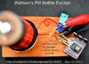
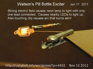 This was originally on my now extinct watsonseblog. I got the idea from a Youtube video, I believe it was called the Slayer Exciter. The circuit is very simple; it’s somewhat similar to the Joule Thief.
Coil
See the attached photo. The coil consists of a pill bottle that is 3-1/4 inches long and about 1 inch inside diameter. I wound on a layer of 30 AWG enameled wire, enough to cover the outside to within about 1/8 inch (4mm) of the ends, and I taped the wire at the ends to hold it in place. I could still fit the bottle cap on the bottle. At the top of the coil (bottom of the pill bottle) I drilled a 1/8 inch hole and put a 4-40 by 1 inch screw, head inside of the bottle and a nut on the outside. I stripped the enamel insulation off the wires on both ends and wrapped the top end wire around the screw threads, and tightened a second nut down onto the first nut to hold the wire. This will be the high voltage terminal.
I wound four turns of 20 AWG (the heavy red wire in the photo) at the bottom (cap end) of the coil, and I taped it with black electrical tape to hold it. I left about two inches (50mm) of wire loose to make the connections to the circuit. I mounted the bottle cap to a small piece of wood with a screw to hold the coil upright, Tesla Coil style.
I mounted a BD135 NPN transistor to a small heatsink (I later changed this to a BD433 to handle more current and power). I soldered the bottom (cap) end of the heavy red wire to the positive side of the bypass capacitor (blue cube in photo). I soldered the other end of the heavy red wire to the center (collector) lead of the transistor (spreading the transistor’s legs apart helps prevent shorts). I soldered the other side of the bypass capacitor to the emitter leg of the transistor (see photo). I soldered the base leg of the transistor to the 10k and 22k paralleled resistors (I should have used a 6.8k instead). I soldered the other end of the resistors to the positive of the bypass capacitor.
I soldered the cathode (flat spot) lead of the red LED to the base lead, along with the thin red wire from the HV coil. I soldered the LED’s other anode lead to the emitter and negative. This seems backwards, and it is. The LED does not come on when the base voltage is positive, but comes on when the base voltage goes negative more than two volts, protecting the base to emitter junction against excessive negative voltage – that’s the whole reason why it’s there.
If the HV electrode doesn’t have HV or the LED doesn’t light up, and the supply current is low, it is probably not oscillating. The cause may be that the winding with the heavy wire is connected backward. It may start to oscillate if the two heavy wires are swapped. But mine oscillates with the winding end closest to the cap connected to the positive supply. Looking at the coil from the top, mine has the HV winding wound clockwise from the bottom to top. The primary or heavy wire is also wound clockwise from the bottom.
Performance
The screw on the top end is the HV electrode. I started out at 1.5V and cranked up the voltage to see how it was going to work. 5V gave me enough HV to light up a CFL light. I got up to 8 volts and the current was around 200 milliamps but varied greatly with the load on the HV electrode. The LED also lit up dimly or brightly depending on the load. I could touch my finger to the HV electrode and see a very small spark, and smell the smell of burnt flesh, and see a spot on my finger. Sometimes I could feel a sting. The small heatsink got warm, but not hot.
An Improvement??
The videos on Youtube show some experimenters inserting a core into the coil, such as a ferrite toroid. I have a handful of the Goldmine G6683 toroid cores, that used to be five for a dollar but are no longer in stock. They are 25mm (.983″) O.D., 13mm (.508″) I.D., and 9mm (.354″) H. I taped two of them together and put them inside of the pill bottle at the base where both windings are. This changed the inductance but I didn’t notice any change in performance.
WARNING
In my experimenting, I only used about 8 volts on the circuit. Some others who are much braver and IMHO more foolish used voltages 12 or maybe more. You should remember that when the voltage is increased 41 percent, the current is also increased by 41 percent, and you are doubling the amount of power into the circuit. This is pushing the transistor closer and closer to the brink of destruction, and it is advisable to have a reasonably large supply of spare transistors on hand if you’re going to play this risky game.
The transistors I’ve used with a Joule Thief are meant to be used in low voltage, high current applications. The exciter demands much higher voltage performance, and this will exceed most Joule Thief transistors maximum ratings, not to mention they would get extremely hot very quickly.
Some have managed to get high enough voltage from the HV winding to cause the corona discharge, the blue glow around the terminal that can be seen in the dark. One other thing that might help is to get a good quality capacitor and use it in parallel with the winding to cause the circuit to resonate, and it may help increase the spark. This is what is done in the older Kettering type of ignition coils used in cars with points and a ‘condenser’ which is the capacitor, across the points. The value of this condenser is typically 0.2 uF.
Back to experimenting…
