I bought a Joule Thief at the store today. Well actually there’s more to it than just that. Yesterday I stopped by Harbor Freight and bought a heat gun (that’s another story) and I saw something that caught my interest. It was a battery tester for $2.50 that had three LEDs. It tested two kinds of batteries; a 9V and a 1.5V battery. It looked like this one, but with three LEDs instead of the meter. It used the tested battery to power the LEDs. I could see testing the 9V, because all it needed was some resistors and the red, yellow and green LEDs. But in order to test a 1.5v cell and light a 2 to 3 volt LED, it must have some kind of voltage boost circuit.
I got home and tested a few AA cells with it. I was surprised how the LEDs switched on and off abruptly, no blending of any two colors. And they were bright even though the AA cell was between 0.9 and 1.2 volts, which was the red “Replace” LED. I was thinking about how they were getting this gadget to work at such a low voltage. The only thing I could come up with was that it used a Joule Thief type of circuit to boost the voltage to run the circuit. My curiosity got the best of me and I decided I had to open it up to see how it worked. But I needed to use it to test more batteries and I didn’t want to damage it. So I waited for today to buy another one to open up and examine.
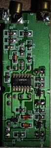
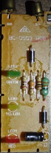
 I managed to get a small screwdriver between the two halves of the case and pry it open gently. It finally came apart revealing the circuit board. The circuit was quite complicated for a device that was so simple externally, just three LEDs. Most of the components were surface mount on the copper side of the board, but there were seven parts and three LEDs on the other side. I found 2 transistors, a 33 microhenry choke, a 1N5819 Schottky rectifier, a 47 uF capacitor and a BAP16 voltage regulator, which apparently made up the DC-DC voltage boost circuit. The main circuit used a LM324, which is a quad opamp, but in this case is used as a window comparator.
There are two 12 ohm resistors and a ceramic capacitor across the 1.5V battery input, so there is a 250 milliamp load on the battery when a fresh 1.5V battery is connected. The 9V input has a 470 ohm load resistor, so the load current is 19 milliamps. However these values do not include the current needed to run the circuit and LEDs.
I haven’t had a chance to sit down and draw a schematic of what I saw, but if one googles for window comparator and/or battery tester they will come up with some circuits to give an idea of how it works. One somewhat similar circuit is here, but in Czech, so you may want to use a translator to get a somewhat understandable version.