 A few years ago I made a LED tester that used a 9V wall wart, a 5V zener for a shunt regulator, and three 100 ohm resistors to limit the LED current – one resistor for each LED socket. The problem with this was that it was plugged in all the time and since it was shunt regulated, it wasted power all the time. Even without the regulator, the wall wart itself wastes a few watts just being plugged in. So I decided to go greener and eliminate the waste of electric power from the wall, and instead use a battery to test LEDs.
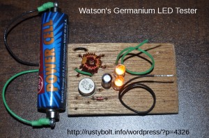
I built this germanium Joule Thief on a small piece of thin veneer plywood; it smelled like cedar when I cut it. I drilled the holes with a pin vise and a small drill, might have been 1/16 inch diameter. The germanium transistor is a 2N525, made by ETCO. This company went out of business back in the early days, so if someone knows the date of their demise, it would be a good date to state that this transistor was at least that old – my guess is early 1960s.
I got the toroid core out of a dead CFL light. Each winding is 122 microhenrys. There are three windings, one wound by itself and the other two wound bifilar. I connected the two bifilar windings together in parallel. The wire I used was 30 AWG or .25 mm.
The resistor was 1000 ohms. The 2N525 is PNP so the battery positive is connected to the common and emitter. Therefore the pulses at the collector are more negative, therefore the 1N4148 diode must have its cathode tied to the collector, and its anode connected to the negative lead of the 10 uF electrolytic capacitor. The positive of the capacitor was connected to the positive common.
Then I connected two yellow LEDs in series and connected both across the 10uF capacitor. These yellow LEDs act as a voltage limiter, and start conducting when the voltage across them gets to negative 4 volts – MOST LEDs have a maximum of 5V in the reverse direction. For testing, I connected two wires across the capacitor. If any type of LED is connected to those coiled wires, it will light up and all of the current will go through the LED, and the two yellow LEDs will no longer conduct and will go dark. All of the current that was going through the yellow LEDs will be diverted through the single LED connected to the coiled wires.
I haven’t yet soldered alligator clips to these coiled leads. I think that it also needs an On/Off switch, but the battery ‘holder’ is easily disconnected from the battery, so maybe not. Update: I added an On/Off switch under the green coiled wire. I also added a spring clamp to the underside of the board, which is one end of a metal battery holder with the contact removed. It grips the middle of the battery firmly, so it will not fall out.
Another idea I thought of was to add automatic shutoff, but I don’t think it would work on a battery that is below a half volt – as it is. it will work down to 1/4 volt or even less.
The circuit draws about 40 milliamps from a 1.5V supply. The frequency is about 95 kHz.
Back to experimenting…