


 This circuit is connected across the phone line, and the pushbutton switch is placed close to the phone. When the pushbutton is pressed, the red LED lights up. The circuit is polarity sensitive so if the LED does not light, then the connections may have to be reversed. Once the LED is lit, the phone can be hung up, and then the other extension may be picked up. As soon as either phone is picked up, the LED will go out and conversation can resume.

2012-09-19 Telephone Hold Circuit


2012-09-18 Joule Thief Won’t Take Beauty Prize
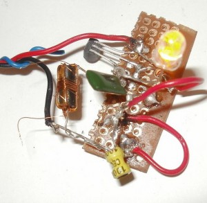 I found this picture of a Joule Thief on this forum, but it requires login, so I’m going to post it here. This sure won’t take a prize for beauty, to put it mildly, but if it works, that’s what counts. I’m wondering how that coil can work with all those weird wires around it. I think it’s a mystery coil. Also, it’s odd that none of the parts seem to go through the holes where parts normally go. Another oddity.
2012-09-17 Reasons to NOT use a 2N3904 In A JT
Reasons to not use a 2N3904 in a Joule Thief or other high current circuit
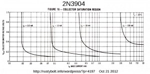 I’ve said this more than just a few times before: when used in a Joule Thief circuit, the 2N3904 is pushed beyond its ratings and gives below standard performance. The maximum ratings for the 2N3904 are 200 milliamps collector current, which is not enough for a conventional Joule Thief.
One might contend that going over the 200 mA maximum doesn’t really hurt the transistor. But the point isn’t that it might hurt something, the point is that going over puts the design into an area where the transistor was not designed to be, and the transistor will give poor performance. In the attached graph, the 2N3904’s collector current is shown with the line labeled Ic = 100mA. No matter how much the base current is, the line can’t get below 0.35V. At a collector current of 200mA, just guesstimating where the line would be is that the line would not go below a half volt. Let’s take the following theoretical example.
The JT circuit requires 250 milliamps peak current. The 2N3904 is turned fully on and the peak current climbs to 250 mA, but the voltage drop from collector to emitter is excessive, it climbs to 1/2 volt. So the transistor has 0.25 amp and 0.5 volt drop, and volts times amps equal power: 0.25 times 0.5 equals 0.125 watt, or 1/8 watt. The LED requires 20 mA at 3.2 volts for full brightness, and that equals 64 milliwatts. The 2N3904 is wasting about twice as much power as the LED requires!
By simply changing the 2N3904 to a 2N4401, PN2222A or BC337, the voltage drop collector to emitter will go down to 0.2 volt, and the wasted power will drastically decrease. The LED gets more power, the battery has to supply less power, and the circuit is no longer pushing the transistor past its maximum limit.
One of the marks of a good design is choosing the right components. The 2N3904 is not a good choice for a Joule Thief.
Back to experimenting…
2012-09-16 Early Rockwell, TI, HP Calculators
I liked this story about the Rockwell 63R calculator – it’s about 2/3rds of the way down on this web page. I still have the one I bought with the help of a Rockwell employee who got me a very good discount. I also have another one that I picked up later. I used mine for a few years during my college classes, then bought the TI SR-56 which I still have, but it now has one bad LED digit (see photo). I really liked it. I remember that it didn’t have the quirk (I don’t think it was an error) that the 63R had, but I can’t remember what that was.
My SR-56 was a great calculator; it could be programmed with simple key stroke sequences and pauses to input the data. But the display used power hungry red LEDs, and I had to sit next to a wall outlet in class in case the batteries ran down in the middle of a test or whatever. When the fourth digit went dead (see photo), I started multiplying the result by ten to shift everything to the left one digit, so I could read that value. I have opened up the TI SR-56 to see if there was a way to repair the bad digit, but it seems that the problem is inside of the display. That’s not possible to fix, so I can just use it for a cool looking display, since it’s really a lame calculator.
By that time, the prices of calculators were dropping and they came out with the LCD liquid crystal display. The batteries would literally last forever. I went to Sav-On to buy a Sharp scientific calculator and I noticed that it said 3V, 0.0002 W on the back. That’s 2/10 of a milliwatt, or 200 microwatts! A very tiny amount of power for the calculator’s two AA cells. I went up to the cashier to pay for it, and she said that she would sell me two alkaline batteries to replace those cheap batteries included in the package. I said NO firmly. knowing that there was absolutely no reason for them to be better than the ones already in the package. They had the Sharp name on them, and I used the calculator with those Sharp batteries for many years with no problems.
I bought the HP 20S calculator, which is not RPN, just a regular algebraic calculator. Then I liked it so much I bought another one, even though they were twice the price of other comparable calculators, I have had other calculators but they seemed to go bad a few years after I bought them. Usually the problem was the keys would give double or triple digits when pressed. Sometimes the LCD display would fail on one or more segments or digits. The typical calculators were made with a case that snaps together, no screws. Obviously they didn’t design them to be repairable. I’ve taken a few apart, and found little or nothing inside other than the keyboard, the display, the batteries and a black blob on the circuit board, which is called COB, or chip on board. Everything is made so cheaply that there is no way to repair it.
Later I got another TI calculator, the TI 30 Solar. I still use it, actually them, because I bought several. They have a solar cell and don’t need batteries. I’ve noticed that almost all of the scientific calculators have binary to hexadecimal conversion that gives errors or the wrong answer. The TI and most of the other brands have this issue. There are a very few that do not, including the HP 20S. I set the HP 20S to BIN and enter 1011001100, then convert it to HEX, and it says 2CC, which is correct. Then I convert it back to BIN and it again correctly says 1011001100. But I try that on another calculator such as the Sharp EL-501V. I set it to BIN and enter 1011001100, then convert it to HEX, and it incorrectly displays FFFFFFFECC. Then I enter 2CC in hexadecimal and convert it to BIN and it gives E for error. Most calculators have this issue, and it’s fortunate that very few people use binary to hexadecimal conversion, This is why I like the TI 30xa Solar, because it simply doesn’t have binary or hex.
I’m back with a new calculator,. the HP 50G graphing calculator. It’s programmable and even has an SD card slot. I have a lot to learn before I’ ll be proficient with it.
2012-09-15 Flashlight Made Of ABS Plastic Pipe
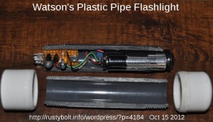 I did this a few years ago and blogged it in my watsonseblog, now gone for more than a year. I guess it’s about time I did it again. The circuit is the two transistor circuit with a 2SD639 high current transistor for the output – it’s the same circuit I used in the flashlight in this blog. It can push a lot of current through the two LEDs connected in series.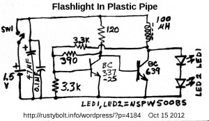
I don’t remember where I got the schematic, but it is not the typical two transistor circuit. It does not use a coupling capacitor between the output and input. The resistance values are unusual, too. But it works.
2012-09-14 9V Battery Substitute
DMMs All Over The Place – I have more than a half dozen of those cheapo Cen-Tech DMMs from Harbor Freight laying around my house, and I use them a lot for checking the AA and AAA cells that I’m constantly trying to drain with my germanium Joule Thiefs with their multicolored LEDs, of which I have several going. The cells still have enough juice in them to keep the JTs powered for a week, even though they only have a volt when I put them on the germanium JTs. I’ve been trying to use up those old AA cells; some have date codes of the late 1980s. Seriously. But I digress.
All those DMMs have been used for more than a year; I haven’t bought any in quite awhile. The funny part about it is the test leads or lead wires go bad before the battery does. I’ve got a couple of the meters where I cut the banana plug end off the wire and threaded the wire through the socket in the meter, and soldered it to the PC board inside. I can’t remember the last time I needed to unplug the leads, so this works great for fixing the problem with the wire going bad at the plug end. Sometimes the probe end goes bad and I cut it off and solder an alligator clip on it instead. That works good, too.
I have a few other good meters, too. One is a Fluke 77, and another is a B&K DMM with a frequency range which really comes in handy when working on JTs. It has an auto shutoff so the battery in it has been going for years. But the Cen-Tech DMMs don’t and they have been left on on occasion until the 9V “Extra Heavy Battery” (that’s what it says!) goes dead. So I thought about changing the meter so that it will run off a single AA or AAA cell.
I measured the current from the 9V to the meter, and it measures the most when it’s on the resistance range, something close to 4 milliamps. That’s quite low and the reason why the batteries last so long. The total power is 9V times .004A or 36 milliwatts. I could make a Joule Thief DC to DC converter and it would easily be able to supply that much current.
I’ve made my own 1.5V or 3V to 9V DC to DC converters; they’re good designs. I was looking at this article (some English; mostly in Czech) about a 9V substitute. looking at some other circuits, also. One of them is Roman Black’s V boost circuit. His goes from 5V to 13V, I would change it from 1.5V or 3V to 9V. The circuit uses a zener on the output to do the regulation so it’s inefficient since all the excess power is wasted in the zener.
I’m Looking at other circuits too. I found one that was posted to a forum, but it’s only accessible to those registered and logged in. To regulate, it uses a zener and another transistor to shunt the base bias of the driver transistor to ground. This is less wasteful than the Black brute force regulation method but still wastes a few milliwatts, which is something that could be saved when using a battery.
I have thought about using rechargeable batteries. I have also thought seriously about using a supercapacitor in place of the battery. The advantage of a supercapacitor is that the rechargeable battery may take hours to charge, the supercapacitor just a few minutes. However, the rechargeable battery can be swapped out for an already charged battery. The one thing I really don’t like about rechargeable batteries is that they lose 1 percent of their charge per day, so every month 1/3 of the charge just disappears without any use. This means that one is constantly recharging them no matter how much they get used.
I have some 10 Farad and 50 Farad capacitors, both at about 2.5 volts. They should hold enough charge to run for tens of minutes, long enough to make enough measurements. I have some 2600 Farad ultracaps but they’re the size of a soft drink can and too large and unwieldy to be used, I think. I have thought about just plugging a 9V AC adapter ‘wall wart’ into the back of the DMM, but this is a safety hazard. If the meter is used to measure something such as the AC line or high voltage, it could go through the meter, and through the adapter, and cause the meter to short out the measured device, or worse yet shock someone or cause a fire. When a 9V battery is used, it is completely contained inside of the meter and there is no shock risk. That is also something I have to consider when I build a battery substitute. The substitute has to be insulated if it is not totally enclosed inside of the meter. The insulation will have to handle hundreds of volts, maybe as high as a thousand volts. The supercapacitor is only 2.5 volts, so it will need a DC to DC converter to bring it up to 9V, and a jack to charge it up periodically.
I still haven’t made up my mind as to which method I want to pursue. I may just do one of each and see how they work out, and compare them. Like, learn from experience, huh?
2012-09-13 JT Blinker Using Single Winding Coil
I was discussing with Aki (theledart.com) his JT blinker, which uses a single winding coil, two transistors for the “JT” V booster, and two transistors in an astable multivibrator to blink the “JT”. He asked me to include the schematic.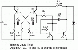
The first circuit boards that I had made from ExpressPCB.com used an astable multivibrator. I wanted to extend the battery life by turning the LED on for only a short time during the flash. I used ten times more resistance in one of the base bias resistors so that the astable MVB stayed on about 10% and was off for 90%. Assuming a flash rate of 1 second, the LED was on for about 1/10 of a second or 100 milliseconds (the actual flash rate was 1.2 per second). This cut the average battery drain down to ten percent of its full-on current and extended the battery life probably by ten times.
But then I built my Blue Blinky and on Dec 1, 2007 I put in a partly used AA cell. It ran for 21 months on that cell, much much longer than the flasher that used the astable MVB. I measured the on time of my Blue Blinky and the LED was on for only about 4 milliseconds, much shorter than the 100 milliseconds that the astable MVB was on. It was obvious that that was the reason why the Blue Blinky battery lasted for so long. Even though it was on a shorter time, the flash was still bright.
The Blue Blinky uses a two transistor flasher circuit like the ones in Bill Bowden’s hobby circuits. These have been around since the transistor was first made available commercially. The circuit was used in road barricades that had the yellow flasher light.
At that time, transistors were only made of germanium and could operate down to less than a quarter volt. Germaniums are no longer available and were replaced by silicon transistors, and since silicon transistors stop operating at a half a volt, the battery is not as ‘used up’ as it once was and still has a half volt in it.
Many experimenters want to ‘harvest’ that last half volt. They try to come up with some way of extending the Joule Thief down to below a half volt. I have already shown how to do that. But anyone can take two half volt batteries and put them in series, and then the Joule Thief will run them down to a half volt total, or 1/4 volt each.
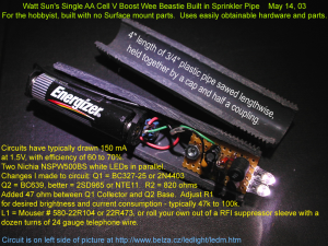
About the Joule Thief part of the circuit – Aki said he likes a simple single winding coil. I found that I was spending more than a dollar apiece for the 100 microhenry chokes I was using in my early designs. Later I found that I could buy a Fair-Rite 2673002402 “suppressor sleeve” which is really a toroid core, for 12 cents apiece from Mouser. I then had plenty of telephone wire in my junk box, and all it took was two 6 inch pieces of red and green 24 AWG telephone wire (about a foot (30 cm) total), and about a minute to wind them bifilar around the toroid core. Voila! A Joule Thief coil with about 150 microhenrys per winding that costs 14 cents. You can also use this for a single winding voltage boost circuit and it’s a lot cheaper than buying prewound chokes. I think that an experimenter should be willing to invest a little ‘sweat equity’ into his or her projects. And it always helps if that sweat equity pays off in the long run by saving money.
But if you’re hooked on the chokes, you can make a conventional single transistor JT by using two chokes. The first choke serves as the primary winding, and the second choke is positioned next to the first and acts as the feedback winding. It picks up the magnetic field from the first choke and inverts it, and this is fed to the transistor’s base, just like the two winding coil. You have to have the second choke positioned the correct way; one way will work, the other won’t. If it doesn’t oscillate, then the position of the feedback choke has to be flipped end for end. Once they are working, it is a good idea to glue them together with silicone glue or hot glue so they won’t move apart. Tape or shrink tubing would also work. I personally think this is a poor design because I have never seen this used in any commercial equipment, and never seen it used in any experimenter’s JT on the ‘net. But it does work.
Conclusion – The results of my experiments show that if you’re looking for the longest battery life for your flasher, then it is best to use a circuit like the Blue Blinky that turns on the JT for a very brief period, so that the LED gets a high peak current during the flash, and the average current drain is very low. You can find more very low power battery flashers in Dave Johnson’s discovercircuits.com. Go here and look for flashers.
2012-09-11 Making a display from a row of LEDs
A few years ago I saw a video on Youtube for a car wheel light that displayed a message as the wheel rotated. I have seen this same method used on LED lights for bicycle wheels. It was a row of LEDs that were synchronized to the rotation, and as the wheel rotated a few degrees, the LEDs would display the column of a many columned display. As the wheel advanced, the persistence of vision created the message around the perimeter of the wheel. Later I went to Radio Shack and they were selling a small, hand held, battery powered fan with a row of LEDs on one of the blades. When you pressed the button, it displayed a message. The salesdroid demoed it for me: it said <expletive> Radio Shack!
The software somehow senses when the blade passes a certain point so it can begin to display the message. The rest is just turning the LEDs off and on in the right order and time.
Aki said he was aware of this and thought about including it in his projects. I was discussing the wheel lights and fan above with the idea that it might be possible to use it in the Wave JT. I thought about how one would mount a small device onto a rotating wheel, but it seems a little bit too complicated for the Wave JT since there are no mounting holes. I later thought about it and I figure that it might be a lot easier to use an arm wave. Like when the button is released there is a burst of LED activity that’s the columns for a few characters being displayed. If the Wave JT is waved – no pun intended – the few characters would appear in the air. This is just enough to display some initial information that would indicate the state of the Wave JT. It’s not a lot but enough to help communicate what’s going on. Two digits can give us the item in a list of a hundred different states of the device. There are other ways to do this. The eight LED could be flashed in two ‘digits’, from 1 1 to 8 8. Zero doesn’t show, and the higher numbers are more difficult to count correctly and may require longer to display.
2012-09-10 Hybrid Ge – Si Joule Thief
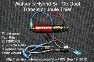 I’ve been running some AA and AAA cells on a few Joule Thiefs that use silicon transistors until the cell gets down to about a half volt, then I switch the cell to a germanium Joule Thief and run it until the LED goes out and there’s typically less than a quarter volt left in the cell. Some of the AA and AAA cells are way, way out of date, like the 1990s and even a few from the late ’80s. Believe it or not, these still have enough juice in them to light up a JT fairly bright. But I’ve had some of them leak, so I decided I have to get rid of them, so why not run some JTs while I’m getting rid of them?
The solution to the leakage problem is to use a pair of small magnets to hold the wires on to the ends of the cell. If it leaks, the corrosion only affects the small magnets and usually can be scraped off the magnet so it can be reused.
But I wanted to get rid of having to switch from silicon to germanium Joule Thiefs. Why not combine them into one? Good idea.
I decided that an easy way to do this is to parallel one of each transistor. If the germanium is a PNP, then I’ll have to use a PNP silicon such as the 2N4403 or BC327. The emitters and collectors of both Si and Ge transistors are connected together. The existing 1k resistor to the silicon is still used, and another 1k resistor is connected to the second transistor’s base and the winding lead that’s going to the original 1k. See the attached photo. The BC327 silicon transistor (black plastic case) is nestled between the leads of the 2N404 germanium transistor ( larger metal case).
Downshift – When the cell has more than a half volt left, the silicon and germanium transistors will both switch current to the coil. As the cell voltage drops below 1/2 volt, the silicon stops working, and the germanium continues to switch current until the cell voltage drops below a quarter volt. Then both transistors stop, and the cell is thoroughly drained and ready for the trash can.
Also, the germanium transistor will start up with 1/4 volt from the cell, and the silicon transistor will then go along for the ride, idling in the background. The two transistors should give more current to the LED than a single transistor, but I haven’t measured the LED current yet.
I’ll have to convert a couple of the JTs I’m using and see how it works. Well, I’ve already done that, as evidenced by the mess of wires in the photo. I have some germanium transistors that are NPN so I won’t have to switch the polarity of the JT.
Another thought – I could add a third winding to the coil and put it in series with the existing feedback winding. The idea is the germanium transistor using the existing feedback winding would get the JT running when the cell voltage is less than 1/2 volt, and the added winding would boost the voltage to get the silicon transistor conducting even though the cell voltage is low. Another thought: use this added winding to drive the gate of a 2N7000 MOSFET, and see if the two transistors will run at very low cell voltages. Also, if the winding was isolated it could be rectified, filtered and the DC used to provide a several volt supply to drive the gate of a larger MOSFET. Essentially the idea here is to use the germanium transistor just for minimal current generation for supplying the higher voltage the larger switching transistor needs. But I have to remember that I have already done a similar thing with regular silicon transistors.
I did a few tests with ‘dead’ batteries. It works, giving a lot less light when the cell is below a half volt, but it drains the cell, which is my main objective.
Back to experimenting…

