default

2013-06-17 LED “Corn Cob” Light on eBay Continued

This is a continuation of the original June 14 blog.
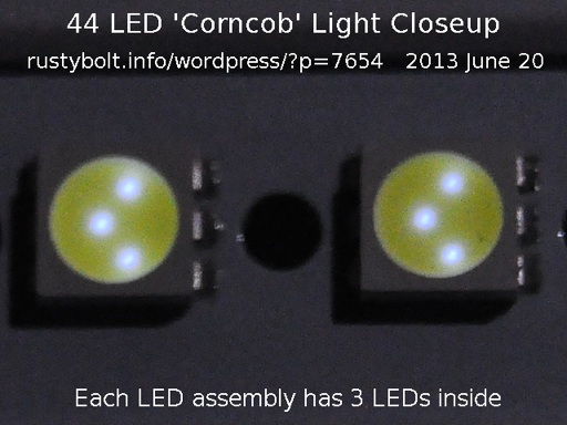
DSC_0379S4

Click on it more than once to enlarge

I don’t think I mentioned this earlier, but the 44 LED light circuit is so simple that there is no regulation, so the LEDs can be dimmed by reducing the AC voltage.  I used a sine wave variable AC voltage.  But most conventional dimmers use a circuit that chops out part of  the AC sine wave every 1/120 of a second.  During the time the dimmer is on, the peak voltage can still be over a hundred volts, but to the incandescent bulb, it looks like the low AC voltage on the average.  The problem is typical CFL and LED lights don’t see it this way; they see the peak voltage and dim very little.

WARNING: With all  the exposed bare wires that are easily touched, there is a great danger of being shocked.  That’s why I set the measurement up before I applied power.

I arranged the LED panels on the wood floor and connected up a DMM to one 6-LED panel, and the other to the AC input.  For the AC input I used a variable AC source, the same sine wave as from the AC line.  I adjusted the AC to various voltage and these are some of my observations.

The LEDs start to glow at about 40 VAC.  Not enough light to illuminate.

They put out decent light at about 75 VAC, and the DC across one of the 6-LED panels was 17.14 VDC.

At the following AC voltages, the corresponding DC voltages were:

90VAC == 17.53 VDC

110 VAC == 17.89 VDC

115 VAC == 17.93 VDC

120 VAC == 17.98 VDC

125 VAC == 18.04 VDC

After the test, the 6 LED strips got moderately warm.  But it must be pointed out that they were spread out on the floor, where plenty of air could get to them.  I’m sure that they would get much hotter when they are packed into the light base.

Some Calculations

My objective is to find out how much current each LED needs.  I want to disconnect the six LED strips from this LED light and mount them onto a flat heat absorbing surface.  I can then add six current limiting resistors and a power supply   Each strip has 5 holes, so I could screw two small screws through the holes to mount it to a thin flat strip of aluminum.  I can then mount this under the cupboard in the kitchen, and have a 6W LED strip light that lights my kitchen counter.

According to the measurements, six LEDs in series have about 17.96 VDC across them when the AC line is 117VAC.  Therefore a single LED should have about 17.96V/6 or 2.993V.  And since there are 22 LEDs in each series string, the total DCV across them is about 65.85VDC.

117VAC rectified and filtered is about 165.5VDC, and subtracting 1.2V for the full wave bridge rectifier, leaves about 164VDC.  Subtracting the 65.85V, leaves 99.6VDC.  It takes an AC voltage of 99.6 / sqrt(2) to make the 99.5VDC, which calculates to 70.43VAC.  So the circuit has to drop 70.43 VAC volts across the capacitors.

So far, I don’t know what the total LED current is, because I have not connected an ammeter in the circuit.  But we know that the total of the two rust red capacitors is 3.7 uF.

The reactance of 3.7 uF at 60 Hz is 717 ohms.  I divide the 70.43 VAC by 717 and it is 0.098 amps.  The total current through both strings of 22 LEDs in parallel is 98.2 milliamps.  Assuming that this current is split equally into 1/2 for each string, that gives 49 .1 milliamps for each string of 22 LEDs.  So we now know that each LED has a little less than 50 milliamps going through it.

I found the V drop across each LED was 2.993V or about 3 volts, and the current was 50 mA, so each LED is dissipating 150 milliwatts.

With the above information I can calculate the current limiting resistor needed for a given supply voltage and a strip of 6 LEDs.  Assuming that I have a 24VDC supply and the LED strip requires 18V, the resistor must be 6V / 0.05 A, or 120 ohms.

Update June 22 – In his comment, Kirk reminded me that these low power AC line operated devices typically have a resistor or NTC resistor in series with the incoming AC line .  I have often seen the resistor, typically 100 ohms as he noted, in series with the incoming line, but I have never seen a NTC (negative temperature coefficient) resistor used, and I’ll explain why.  But first I have to tell my experience with these type of devices.

I have often seen the NTC devices, which typically look like a thick ceramic disk capacitor, in switching power supplies.  They are used to limit the inrush ‘surge’ current when the power supply is first turned on, and as they heat up over a few seconds, their resistance drops to the point where they let the full current through with very low resistance.  Less strain is put on the power supply diodes and filter capacitors, and they are protected from damage from the high surge current.

I maintained a large PBX system, with over a thousand phones.  Each digital phone was connected to the PBX, which furnished 48 volts DC to power the phone.  On the PC boards in the PBX, each phone line was connected to the 48 volts through a special resistor, which as I just said, looked like a thick ceramic disk capacitor.   But this was not a NTC resistor, this was a PTC resistor.  It had very low resistance, something like 8 ohms, as long as it was cold.  But when it heated up, the resistance would increase to the point where the 48 volts could force only a hundred milliamps through it.  This resistance was several hundred ohms, but depended on the temperature.  If there was a short somewhere out there in the thousand or more feet of phone line, this PTC would protect the line from excessive current.  It kind of acted like a fuse, however it had two advantages: it  did not burn out, and it ‘reset’ itself (cooled off) once the short was removed.

Well, the PBX is gone but I scrounged hundreds of those PTC resistors from the boards in the last few years, along with other unique parts.  But going back to the LED light, the reality is that there are no active parts in this corncob light, just a bridge rectifier, filter capacitor, which happens to be rated at twice the maximum rectified voltage, and a series string of LEDs.  The reactance of  the two capacitors acts as a current limiter at 60 Hertz.  There is no need for an inrush limiter when the light is powered on.

However, when the AC line voltage frequency is greater than 60 Hertz, the reactance of the current limiting capacitors is less, and the current could be much higher.  But when is the frequency greater than 60 Hz???  Whenever there is a spike of voltage, which may occur whenever an inductive device such as a motor, relay,  or similar device with a coil is connected to the line.  These have sharp increases in voltage and can go right through the current limiting capacitors like they were not there.  So the circuit designers decided that it would be best to put a resistor in series with the capacitor, so that there would be some  limit to the maximum current.

Also, it should be remembered that when the NTC is used in a power supply, after the initial turn on, their resistance is very low and they offer almost no protection against voltage spikes that might be on the AC line.


default

2013-06-16 1.5 to 9V Converter Uses Supercharged Joule Thief PCB

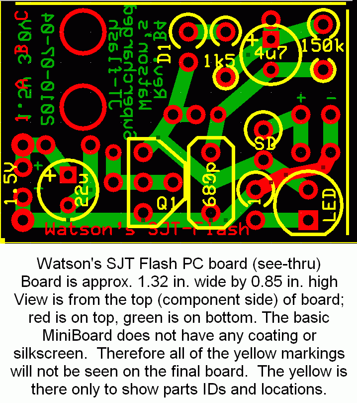
I have built a few dozen of my Supercharged Joule Thief Flashers using the PC boards that I designed and had made with ExpressPCB (schematic is in the link above and PCB picture is below).  The circuit works okay with a fresh battery but when the battery gets low the light comes on solid, and that happens when the battery is below about 1V.  My Blue Blinky does a better job of flashing.  So I decided to use one of the SJT Flasher PC boards as a 1.5V to 9V DC-DC converter.

SJT-Flash-2(PCB)When I designed the board, I added a few traces and holes for the Schottky rectifier ‘SD’ and filter capacitor (no label, just + and -), so the board has the room and is ready to work as a DC-DC converter.  However it’s just a single transistor, there is no other transistor to control the base bias of the SJT.  So I just removed the jumper ‘1’ and put a Zener diode in series with the blue LED.   When the voltage gets up to about 8.6V, the LED and Zener conduct and limit the voltage.  In other words it’s a shunt regulator that wastes the excess power in the LED and Zener.  But because it’s a Supercharged JT, it only draws about 23 mA from the 1.5V supply.

I used a 1N5817 for the Schottky diode, a 470 uF 10V for the capacitor, and a 5.6V, 1/2W Zener.  The output is taken across the LED and Zener. The transistor was a S8050, and the 4u7 capacitor and 150k were removed and replaced with a single jumper.

When I put a 3600 ohm load (about 2.2 mA) across  the output, the voltage dropped from 8.6 to 8.2V.  The supply current remained at 23 mA, — no change.  The frequency was  about 116 kHz.

Since this circuit draws a constant 23 mA from the single cell, it’s not a good choice for powering a DMM or other meter that might be left on for several minutes.  It would be a good choice for a crystal tester, light meter or Gate Dip Oscillator, which are used for only a short period, maybe less than a minute.  There are some gotchas when the circuit is used for a radio.  See my earlier blog on powering the superregen receiver.

default

2013-06-15 Free Energy Advert a Scam?

Ad4FreeEnergy-MaybeScamThe adverts from google popped up a nastily flickering image of someone pointing to a hokey looking device that “power companies hate” because it supposedly saves you a lot of money.  I didn’t click on it because I don’t want to be bombarded with more of those ads, even though I’ve tried with little success to get unsubscribed from those stoopid ads.  I ordered a book on Amazon and after that, the stoopid ads kept wanting to sell me more of the same book!!  That’s why they’re so stoopid!

I just thought that if I post a screen cap of the gadget, someone might have seen it before or recognize it, and leave a comment.  It looks like a bunch of wires and electrical tape wrapped around a soda can.

I bought an Ebook on Free Energy from some company, and I put it on my Kindle and read it, and found that the U.S. government has funded some of these hare-brained schemes.  The book was long on stuff gleaned from the ‘Net, and short on text from the author.  But hey, I learned that I spent my money on something that was overpriced and that I probably could have downloaded most of it for free from the ‘Net.  Maybe P.T. Barnum was right.

I really believe there’s a future out there with an answer to clean, environmentally friendly energy, but I hate those hucksters who take advantage of people with false, misleading information.  And I especially hate it when the hucksters use mainstream advertising media, which exposes even more gullible people to their lies.

Back to experimenting…

default

2013-06-14 LED “Corn Cob” Light on eBay

I found some LED lights on eBay for under 6 dollars U.S. with free shipping.  They’re shipped from Hong Kong, so it will take a few weeks to get here.  They said sometime around the 4th of July.  Wow!  Instead of lighting up firecrackers, I’ll be lighting up LEDs!!  They call these corn cob lights because, well, they look like a corn cob.

Speculation… (skip down to the update for the real truth)

As can be read in the link, they have 44 LEDs, so if all of them are in series, the total voltage would be 44 times 3.2 volts, or 140.8 volts.  This would be fine, since when 120VAC is rectified and filtered, the voltage comes to 120VAC times 1.31, or about 169 volts DC.  There would need to be a series resistor to drop the 28 volts difference.  Assuming that the LED current is 20 mA, that would be 1400 ohms.  However, if there is a capacitor in series with the LEDs, the voltage drop can be across the capacitor.  This also reduces the heat dissipation in the light bulb because the capacitive reactance is not resistive, it’s reactive.

However, another inexpensive LED light that I have opened up has a switching power supply to give about 30 volts to the LEDs. The LEDs are not all connected in series, but in series-parallel.  So I cannot be certain until I receive the LED lights and examine them more closely.  That’s another way of saying that I’ll have  to take one apart to see.  Heh-heh.

I looked at the pictures in the link, and I saw that there were six sides, each with a flat panel of 6 LEDs, plus 8 more LEDs on the top end, for a total of 44 LEDs.  This 44 number seems to limit the number of possible combinations.  These could be divided up into two  series strings of 22 LEDs each, with both strings in parallel.  The division would be three panels of 6 LEDs each, plus four of the 8 top end LEDs.  Thus 22 LEDs times 3.2V per LED would be 70.4 volts DC.  I cannot see how it could be divided up into four series strings of 11 LEDs each, because it would require part of a panel, and that would make it much more difficult.  I’m not saying it can’t be done, however it’s difficult from a wiring perspective.  Another would be 6 panels of 6 LEDs each, and 6 of the 8 LEDs on the top, for a total of 42 LEDs.  But the remaining two LEDs would not be included, so this does not seem to be a possible combination.

Another factor that’s in favor of all 44 LEDs in series is that this does not require any active devices.  All that’s required is to rectify, filter and limit the current.  This is very simple and very cheap, too.  And since the lights are very cheap, it’s a strong indicator of this configuration

Ok, so it seems that easiest one would be all of the 44 LEDs in series.  The circuit that I  come up with is a capacitor in series with the AC input of a bridge rectifier.  After the bridge would be a filter capacitor, maybe 22 or 47 uF at 200VDC.  Then the 44 LEDs would be in series across the filter capacitor.  What would value the series capacitor be?

Earlier I gave the value of 1400 ohms.  At 60 Hz, I calculated that it would be 1.895 microfarads.  But a capacitor rated that value at 250 volts AC, and rated X2 for connection across the AC line, would be very expensive.  Eliminating the X2 rating would save money, but it would be less safe.  The inexpensive night lights and similar AC powered devices do this all the time.  But still, the 1.9 uF capacitor would be large and somewhat expensive.  BTW, there usually is a high value ‘bleeder’ resistor – like 470k – across the capacitors to bleed away the charge when it’s not plugged in.

Another possible way to power the LEDs is with a transformer.  If the panels had their LEDs divided onto 11 groups of 4 LEDs in series, and these 11 were connected in parallel, the voltage across them would be about 3.2V times 4 or 12.8 volts, and 11 times .02 amps would be .220 A or 220 mA.  This would be easily obtainable with a small transformer, rectifier and filter capacitor.  But there would (or should) be 11 current limiting resistors.

Many of the LED lights are not dimmable.  The switching power supply they use tends to regulate the voltage, and this defeats the dimmer.  The complex waveform caused by the dimmer could defeat the current limiting capacitor and cause problems.

The surface mount LEDs that I see in these lights are mounted on a circuit board that is laminated to a flat sheet of aluminum. and the aluminum gets quite warm when it’s lit.  The first thing that I should do is measure the LED current.  I suspect that the current is more than 20 milliamps.  So far I’ve done a lot of speculation but I’ll have to wait until I see the guts to confirm any of this speculation.

DSC_0377S2

Click more than once to enlarge

Update June 19 – I received the corncob lights today.  I was wrong: they shipped from New Jersey so it took only five days.  I put one into the desk lamp and observed that it was truly a bright white – 6000 to 6500 degrees CCT acording to the label on the box.  I also observed that it did not put out as much light as the 40W Cree LED light I’ve been using.

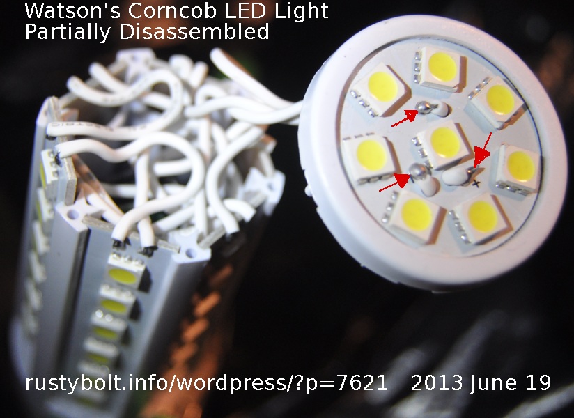
I examined the thin line where the top contacts the sides.  While grasping the body, I pushed on the top with my thumb, and the whole top popped off.  Didn’t take hardly any effort – very little glue, mostly just a friction fit.  I was surprised at the number of wires inside (see the first photo).  None of the wires I saw were color coded – they were all white.  I looked down inside and I see two capacitors but I don’t see any inductors or other small parts.

DSC_0378S2

Click more than once to enlarge

One of the first things I noticed was that there was almost no metal at all in this LED light.  No fins, no heatsinks, no PC boards laminated onto aluminum to keep the LEDs cool.  This means that the light is likely to overheat due to the LEDs getting very hot.

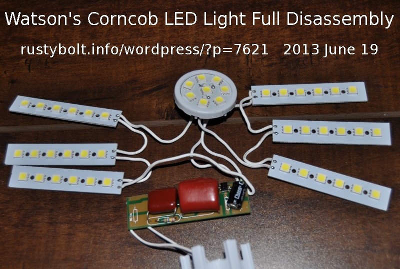
Four of the 6 side boards with 6 LEDs slid out freely when I pushed on them, but two were stuck.  I examined them closer, and found that they had applied a drop of plastic solvent (acetone?) or super glue to two points where the top snapped into the base.  Some of the glue got onto the two stuck boards, so I had to pry on them to crack loose the board from the base.  Once I had all six boards loose, everything slid out easily, including the circuit board inside (see the second photo).

The circuit is simple.  The AC comes in, one lead from the center contact of the screw base goes to the two large rust red colored capacitors, which are connected in parallel.  The larger is 2.2 uF 400V, the smaller is 1.5 uF, 250V.  The other wire from the threaded contact goes directly to the small black bridge rectifier next to the larger rust red capacitor.  These two capacitors act as a current limiter.  The output of the bridge rectifier goes to the black capacitor, which is 4.7 uF, 400VDC.  The rectified, filtered and current limited DC at the right end of the board goes to two strings of LEDs connected in parallel.  Each string consist of three of the 6 LED boards connected in series, and half of the 8 LEDs on the top.  Below the smaller capacitor there is a 560k 1/4 watt resistor that discharges the capacitors when the light is not being powered.

WARNING!  DANGER!

In the first photo I put three red arrows where the top has bare exposed wires that can be touched easily.  Actually, all of the LEDs have bare leads that can be touched.  These may have the AC line voltage on them.  Many of the lamps I own use a two prong power plug, which can be inserted either way into the wall socket.  This means that the either the center contact or the threaded contact of the screw-in base can have 120VAC on it.  Depending on which way the lamp is plugged in, the base wire connected to the bridge rectifier could be 120VAC or neutral.  If it is 120VAC, high voltage could be on those bare wires on the top.  If you’re standing on a cement floor or in the kitchen or bathroom and touch the faucet and the bare wires, you will most likely get shocked.

On most of the CFL lights that I’ve disassembled, I see a 1 ohm metal film fusible resistor between the base contact and the circuit board.  If something shorts out, the fusible resistor opens and protects the circuit from overheating and possible fire.  This LED light HAS NO resistor or fuse for protection.  This is inexcusable.  All that they would need to do is make the PC board wire from the AC to the capacitor very narrow so that it would act like a fuse and open if the current became excessive.  If the bare wires touch something that is grounded, the full AC line voltage could be across the bridge rectifier.  This high current could cause a fire.  So what we have here is a LED light that is both a SHOCK and FIRE HAZARD.  This is a WARNING!

I measured the voltage from the three bare wires on the top to the ground pin of the power outlet.  I got about 50.4 volts AC, which may not be deadly, but is dangerous and also could be a fire hazard.

Update Jun 20 – I am continuing this blog with the blog dated June 17th.  I discuss the results I got when running the corncob LED light at various AC line voltages.


default

2013-06-13 Good Article on Capacitor Leakage, Soakage

Yeah, that’s what I said: What’s soakage?  Well, you can read more about that at the end of the multipage article here.  He also discusses power storage, and most importantly, how not to measure leakage.  The result is that the leakage of the wiring and test leads becomes noticeable, where one would never notice these in a regular circuit.   I’ve put three transistors in a circuit so that they are DC coupled and have a huge current gain, over ten million times.  The remaining parts are a battery, a LED and 2 current limiting resistors.  It takes only nanoamps to turn the transistors on.  Same goes with a MOSFET such as the 2N7000, where the gate lead is left open and can touch other surfaces.  It will also pick up slight leakages in the nanoamps range.

Back to the article.  He shows that it’s important to keep ‘lytics charged up for awhile to ‘reform’ them.  The process that they go through in the factory is called forming, which deposits the insulation coating on the capacitor’s aluminum electrodes.  After time, that thins out so charging them up again reforms the coating.

default

2013-06-12 Current Limiters, 2 Versions

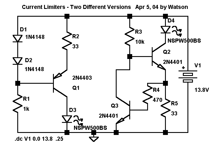
CurrLimiters2Vers-6257I originated this in SwitcherCAD III back inApril of 2004, and posted it to my late watsonseblog.  The one on the right seems to be more commonly used.

default

2013-06-11 CD Drive Motor Lights LED

CD-ROM-gen3802-3086I took this photo Oct 2003 and posted it to my watsonseblog.  The ‘cup holder’ is the sliding drawer that comes out of the CD drive.  Other motors inside can generate enough power to light up the LED.

default

2013-06-10 Calif. Cities And Power Line Frequencies 1940s

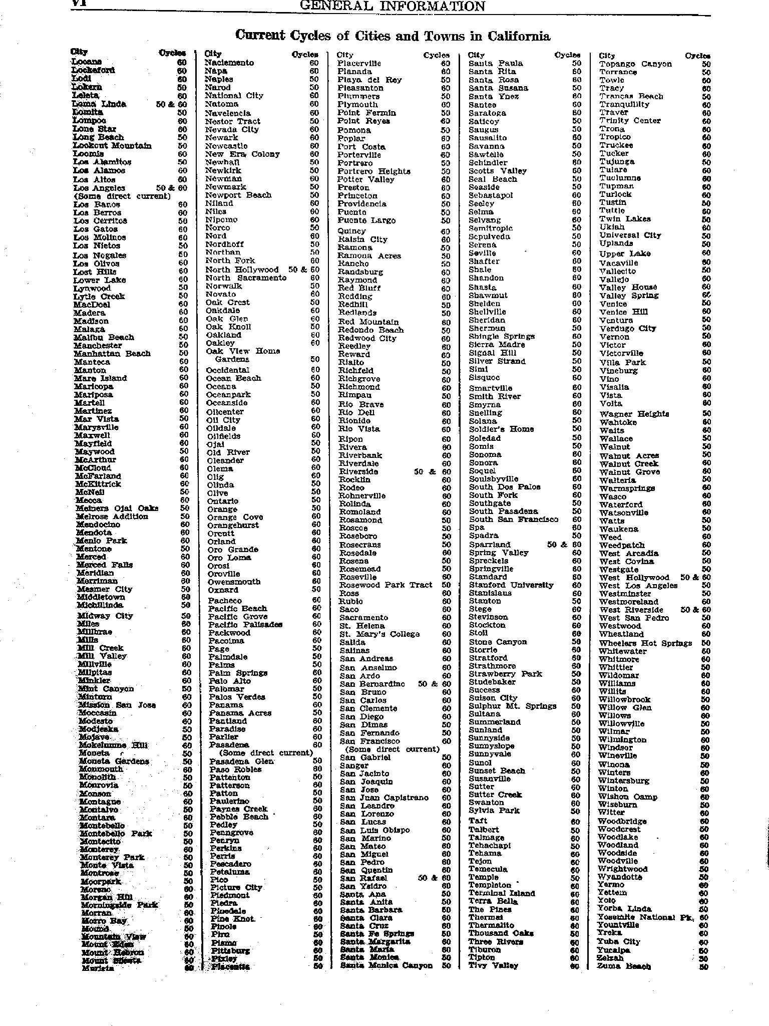
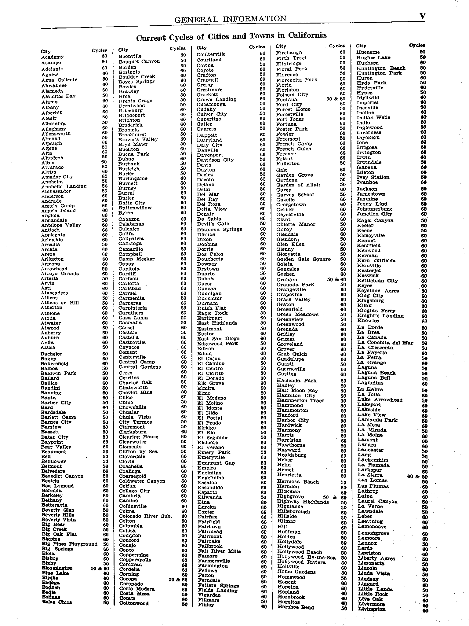
CalifCities&PowerHz4517sCalifCities&PowerHz4516sAn historical document, from an old Union hardware catalog.  This is before the power line frequency was standardized at 60 Hz. across the whole U.S.  I originally posted this to my watsonseblog.

default

2013-06-09 1.5V to 9V DC-DC Converter For Superregen Receiver

In early May I built a Superregenerative FM receiver, and blogged that I should build a 1.5V to 9V DC-DC converter for it.  After testing the second DC-DC converter for the DMM, I think that I can use the same Night Joule Thief board for this receiver.  A few of the component values can be changed to reduce the 9V output current from 6 milliamps to 1 or 2 mA, which is enough for the receiver.  This will also reduce the current needed from the 1.5V cell, which was already only about 10 mA when the DMM was on and 5 mA with no load.  I figure that the no load current can be reduced below 5 mA, possibly 3 mA and with the receiver on, possibly only 6 or 7 mA from the 1.5V cell.  With 7 mA load on a AA cell of 2000 mAh capacity,  that would give about 285 hours, or about 10 to 12 days running 24 hours a day.  With a switch and using it 4 hours a day, that would be about two months.

My one concern is if the converter will cause RF interference in the receiver.  I built something similar for my AM-FM radio, and the interference can be heard loudly on the AM band, however  the FM band works okay.  But this is a full superhet receiver with more noise immunity than a superregenerative receiver.  I guess I’ll have to try it and see.  I have several more things I can do, such as adding a RFI suppressor sleeve to the 9V wiring from the converter.  I could also enclose it in an Altoids tin*, which was what I did for the earlier converter.  The metal tin should shield a large part of the RFI.

Update June 13 — I put together a third Night Joule thief board.  For R1 I used a 1k and for R2 and R2 I used 22k.  The capacitor was 150 pF, same as the other boards.  The transistors were PN2222A for both NPNs and 2N4403 for the PNP.  The coil was a 100 uH small radial choke.  Both filter capacitors were 470 uF.  The rectifier was a 1N4148, and the zener was the emitter to base junction of an old transistor.

The output voltage was 9.2 volts, no load.  The supply current with no load was well under 5 mA, probably 3 mA but it’s hard to read the very low current on a 150 mA analog meter.  With a 4500 ohm load, which is equal to 2 mA, the supply current went up to about 27 mA, and the output voltage was about 9.05 volts.  This will be plenty of current for the superregen receiver, which uses only about 1.1 mA.

With a 2000 mAh alkaline cell and assuming the full 27 mA battery current, the converter should run for 74 hours, or more than three days running 24 hours a day.  At 4 hours a day, that would be about 18 days.  And that’s worst case.  With a 1.1 mA current at 9V, the battery current should be less than 20 mA and the batery life should increase accordingly.    But the overall cost for 1.5V AA cells is so much lower than 9V batteries that it will soon pay for itself in saving the cost of 9V batteries.  For even more savings, use one or two NiMH rechargeable cells.

Now I have to try it out on the receiver, and see of it will not cause interference with the receiver.

*However the Night Joule Thief board is made to have a paper clip loop soldered into each end and the battery is held between these loops.  So it is nice and small, and doesn’t need a container as large as an Altoids tin.

Back to experimenting…

default

2013-06-08 DC-DC Converter For DMMs, 2nd I’ve Built

This is the second one I’ve built.  The first one I built is in my earlier blog – links to the schematic can be found there.

I used the following parts: a 2N3906 for Q1, and PN2222A for both Q2 and Q3.  R1 was 470 ohms, R2 was 10k and R3 was 8.2k.  Both the battery bypass capacitor and the output capacitor were 470 uF.  For the rectifier, I used a 1N5817.  The Zener diode was the emitter to base junction of a selected transistor.  I used a jumper across VR1 and left CDS1 empty.

I have been trying to get the required 6 milliamps output with at least 8 volts output before the circuit starts to limit itself.  The two parts I’ve been changing are the capacitor and the inductor.

I have been using a milliammeter between the power supply and the circuit during these measurements.  The supply is set at 1.5V, but about .05 volt is dropped across the milliammeter, so the actual voltage at the circuit is about 1.45 to 1.48 volts.  I feel that it is better to have the circuit working at less than 1.5V just to make sure it can do the job with a battery that’s getting low.

I first used a 100 pF for the capacitor, and tried a few different inductors.  The circuit would  only put out 7 to 7.5 volts when I put a 1400 ohm load on the output.  I should be able to get 6 milliamps with 8.4 volts across the 1400 ohm load.  Changing inductors helped, but the supply current went up a lot higher than with the first one I built , over 100 mA,  So I added  a variable capacitor, and the 1400 ohm load had about 8.5 volts when I had the capcitor adjusted.  I removed the variable capacitor and measured it, and it was 59 pF.  So I removed the 100 pF capacitor and put a 150 pF capacitor in, and the circuit easily gave me 8.5 volts with the 1400 ohm load was on.  All it took was that added 50 pF to make the circuit put out a lot better.

The first inductor I used was a 100 uH I got from Mouser.  I made most of these inductor changes using the 100 pF capacitor.  With the 100 uH, I could not get enough current with the 1400 ohm load, so I put a 180 uH in parallel.  This increased the output enough to where I was getting 8.6 volts with the 1400 ohm load on.  But the supply current was higher than the first circuit.

I tried a 56 uH surface mount inductor and it did well enough to give more than 8 volts out with the 1400 ohm load.  But the frequency was more than 250 kHz, so I decided to try using an inductance that was greater than 56 uH.

I removed the 56 uH and put two 180 uH inductors in parallel into the circuit.  The circuit would not put out 8 volts with the 1400 ohm load on.  I added a third 180 uH choke in parallel.  This was equivalent to 60 uH.  This gave more than 8 volts with the 1400 ohm load on.  But obviously I now had three chokes hanging on the circuit board.  That wasn’t going to work – there was no room for all three.

So I removed the three chokes and put a single 100 uH choke into the circuit.  This was a larger choke, with lower DC resistance, it did better than the first 100 uH choke, but it still couldn’t put out 8 volts with the 1400 ohm load on.  But it would fit into the board, with very little room to spare.  This is when I decided to try changing the capacitor to 150 pF.  With this choke and the 150 pF capacitor, the output stayed up around 8.5 volts with the 1400 ohm load on.

With the above parts, I measured the no load voltage at 8.85V, and 8.55V with the load.  The frequency was 142 kHz no load and 119 kHz with load.  The supply current was 5 mA no load and 50 mA with the 1400 ohm load.

More about this converter in my blog about a 1.5V to 9V DC-DC converter for a Superregenerative Radio Receiver.

Back to experimenting…

© RustyBolt.Info/wordpress
CyberChimps