


 I think this picture and schematic was posted to my watsonseblog. but it didn’t get posted to this rustybolt.info/wordpress/ blog. It’s a picture of my SJT Flasher with the parts labeled, and a schematic of same (click on the picture more than once to enlarge).
I looked in my folders and found another picture of the PC board. I don’t have a PC running Windoze at home and I can’t access the PC board files on disk because the program that accesses them only runs only under Windoze. This file lets anyone look at all three layers of the PC board at the same time. When I sent the file in to have the PC boards made, the ExpressPCB company did not offer the “Miniboards” with a silkscreen layer (yellow in the picture). They do offer it now, for an additional cost. Paul asked me about this board, and at this time this is as much as I can find. Until I get a Windows PC or the company offers a software version that runs under Linux, I am not able to update the circuit board.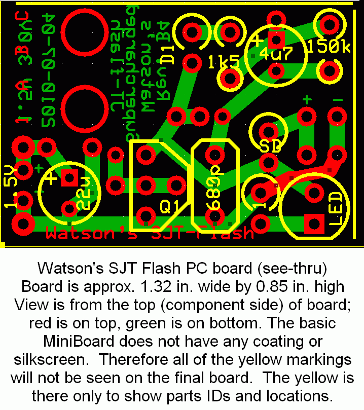
The LED turns on when power is applied, and the 4u7 begins to charge up. When it has charged up, the SJT shuts off and waits for the 150k to discharge the 4u7. Then the cycle repeats. Quantsuff did some experimenting with it on his web page, www.quantsuff.com.
The two smaller holes, one above the 680p and the other next to the collector are the feedback winding leads. The primary leads are near the 22u “+” and collector. The filtered DC output is at the two holes below the + and – holes. Or you can move the LED to these holes.
A 1 ohm resistor or a jumper goes in the holes labeled ‘1’. This is for measuring the LED current. For example, 20 millivolts equals 20 milliamps.
The SD is a (Schottky) diode to rectify the output. The filter capacitor goes in the holes with + and – to the right of the SD.
What you can add to this board is a CdS photocell across (or in place of) the 680p capacitor. The 4u7 should be replaced with a 47 pF or 100 pF capacitor, and the 150k by a 100k pot or whatever resistor you choose to determine the brightness and current.
You can remove the SJT and make it into a regular JT. Just remove the 680p, jumper D1 and the 4u7, and change the 1k5 to whatever resistor you choose to determine the brightness and current.


