Have you ever had one of those days when you think everything’s going along smoothly, and then suddenly you run into a brick wall?
The Sidewalk to Nowhere

Have you ever had one of those days when you think everything’s going along smoothly, and then suddenly you run into a brick wall?
The Sidewalk to Nowhere


I have often seen the conventional Joule Thief circuit used in situations where it is a poor choice – there could be better choices that would do the job.
The Joule Thief or blocking oscillator circuit transfers a low voltage, high current input to a higher voltage, lower current output, with a low efficiency and high losses. It’s a very simple circuit but has serious deficiencies. The typical Joule Thief’s input voltage will be 1.5VDC and the output load will be one LED (or 2 or more LEDs in parallel). The output voltage will be below 5VDC. The parts numbers I have given are for through hole transistors; if you want to use surface mount parts you can also find equivalents for them.
A Joule Thief with a 1k resistor and a small transistor, known as a ‘small signal’ transistor will put out up to 100 milliwatts to a standard 5mm diameter white or blue LED. The power can be reduced by increasing the base resistor from 1000 ohms to 3300, 4700, 10000, or more ohms, and the power to the LED will be reduced along with lower battery current and longer battery life.
If you use a 2N4401, PN2222A, BC337-25, the LED will get about 20 mA or 66 milliwatts with a fresh 1.5V battery. If you use a 2N3904, BC547 or similar transistor, expect to get less than 50 milliwatts, maybe only 30 or 40. The LED will not be as bright.
The Joule Thief circuit puts a heavy demand on the transistor for high current at very low voltage. It has a difficult job driving a single LED. If you want to drive a larger LED or two or more standard LEDs with more than 100 milliwatts, then you will need a higher current transistor specially made for switching very high current at very low voltage. Some common ones are 2SC2500, 2SD5041, KSD5041, ZTX1048A, NTE11, SS8050.
One example of a low voltage source to which a Joule thief might be applied is a solar cell, or solar PV cell. The typical single solar cell puts out a maximum of about a half volt no load and somewhat lower, maybe 0.45 volts with a load. The typical silicon BJT (bipolar junction transistor) takes more than this to start, so using a regular transistor is not a solution. The best solution is to put at least two of the PV cells in series to get a higher voltage, with three or more giving the better efficiency. Even so, using a Joule Thief will lower the efficiency to about 50%, which is excessively high loss. It would be best to use several cells to get 3, 6, or more volts. For best efficiency it is best to do the conversion as close as possible to the cells and run the higher voltage to the load, which saves on the heavier wire that would otherwise be needed.
If additional cells are not possible, then the best way to up-convert a half volt is to use high current MOSFET transistors. A germanium transistor can be used to get enough voltage to start up the circuit, then the operation can be done with the MOSFETs.
Higher Supply Voltage
If the supply voltage is higher than 1.5V, then the Joule Thief may not be the best solution. The conventional Joule thief wastes about half of the power, so if you can use the supply voltage directly without the Joule Thief, it can double the battery life. If the supply voltage is above 3.5 volts, then the LED may be connected directly to the supply with just a simple current limiting resistor. This will save batteries, it will save electronics and the LED will do just as good a job of illumination. The best supply would have three 1.5V cells in series for 4.5V, or four rechargeable cells for 4.8 to 5 volts. Each LED would need a resistor that drops about 1V at 20 milliamps, or 50 ohms. Close values commonly available are 51 ohms or 47 ohms, 1/4 watt. When the battery voltage drops because of multiple LEDs connected to the same battery, this resistance may have to be reduced to maintain the 20 mA through the LEDs.
If the supply voltage is above about 6 or 7 volts and you use a coil with a 1 to 1 turns ratio, the supply voltage will be too high for the transistor. It is necessary to reduce the number of turns on the feedback winding to half the number of turns of the primary. The supply voltage can then be up to about 12 to 14 volts DC. But obviously the total voltage across the LED(s) would be higher than 3.3 volts, so to conform to the rule that the supply voltage must be less than the total voltage across the LED(s), there must be at least 5 LEDs in series. If this sounds confusing, just remember that if the supply voltage is greater than the total forward voltage of the LEDs, they will light up without the Joule Thief circuit, and since the LED(s) connect to the supply through the coil winding with very low resistance, excessively high current will flow through the LED(s), and this will damage or destroy the LED(s).
Some JTers use a two transistor circuit that is mistakenly called a Joule Thief, but is more like an astable multivibrator, but the two transistors’ loads are not equal. The first transistor only drives the second transistor. This circuit does not have the coil voltage fed back to the base, so the voltage limitation of the emitter to base junction is not a concern. The one that uses a NPN for the output transistor and a PNP to drive the output is usually the better choice (scroll down to the 1-Cell Boost Circuit schematic here). But two NPNs work, it’s just that the NPN driver needs a low value resistor to supply the base drive current to the output transistor, where the PNP driver supplies the current, so no resistor is needed – but one is often used.
This circuit can be rearranged so that both transistors drive the coil, and the load is more evenly distributed. The coil uses the two windings of the conventional JT, but both of the transistors’ connectors are connected to them. An example of the schematic can be seen here. This one shows the extra turns on the coil, but it doesn’t have to have those, the rectifiers could be connected to the collectors.
 Update Jul 10 – I put together two LED circuits that both operate from a 5V supply. The first was three LEDs in parallel with 82 ohm current limiting resistor for each LED. The second was a Joule Thief with three white LEDs in series.
For the three in parallel the V drop across each LED was 3.34V, leaving 1.66V across the resistor. The LED current was 20 mA so 1.66V / 0.02 equals 83 ohms. I chose 82 ohm resistors, so the total current for the three LEDs was 60 milliamps. The efficiency of the three LEDs was 66.8 percent.
For the Joule Thief with the same LED current, the supply current was 76.8 mA, and the efficiency was 50 percent.
The conclusion is that the resistors are more efficient and use less current than the Joule Thief. The choice is obvious: the Joule Thief is not the best choice for this circuit.
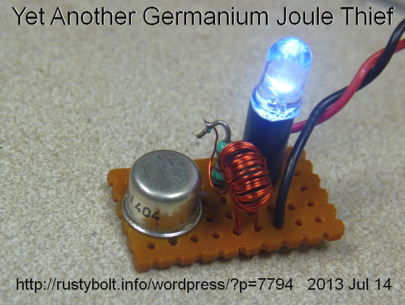 This is one of those Joule Thiefs that uses an old germanium 2N404. But I got them from a German seller on eBay, and I have a suspicion that they were made within the last decade or so, probably by one of the makers in the former soviet bloc countries. I’ve measured true 2N404s and they don’t have high gain like these do.
The LED is white but looks bluish in this picture. It’s still bright even though it’s running off a depleted AA cell, with only 0.87V left in it. The resistor behind the coil is 1k. By the time the LED dims to nothing, the AA cell will be below 0.2V, probably 0.1V or maybe less. That’s DEAD!
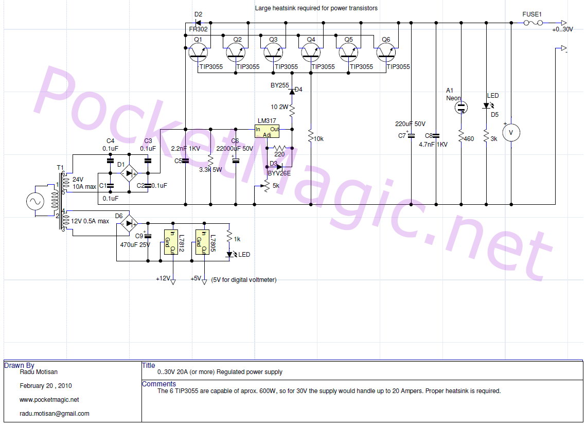
When I work on a Joule Thief I need a power supply that will go all the way down to zero volts. Kirk pointed me to a high current power supply (6 to 8 amp) that puts out zero to 30V and uses a LM317. I have built a power supply that uses a LM317 and goes to zero volts, but it has some very nasty problems (here is a picture of it). Kirk’ss power supply uses a different approach to get the output to zero volts. The designer put three diodes in series with the output of the LM317 to drop the voltage before it gets to the two power transistors.
I believe that every power supply should include the D6 and D10. These protect the power supply. C8 and C9 reduce the output impedance. The fuse in the output protects the PS from overcurrent. But I think the fuse should come before C8, not after.
There are some deficiencies, one serious. I think t he two 4700 uF filter caps at the output of the bridge are not enough to give good filtering at 6 to 8 amps. Somewhere way back in time I read that a good rule of thumb is you need 8300 uF for each amp of current. But that may have applied to audio amplifiers, not regulated power supplies. I would add at least two more.
Another is that at very low voltage and very high current output, the power transistors have to dissipate over 150 watts, so a very large heatsink is required. The power transformer secondary has a center tap, and it would be simple to add a range switch that uses only half the secondary when the PS is on the low voltage range. This would cut the dissipation in half.
The most serious deficiency is the output is open loop – there is no feedback to keep the output equal to the output of the LM317, which is capable of very good regulation. As the current changes from 0 to 6 or 8 amps, the voltage drop across the three diodes, the transistors and the two 0.1 ohm resistors could add up to a volt or more. The drop across the two 0.1 ohm resistors will be 0.4 volts at max current. These drops are not compensated by the LM317, so this power supply does not have good regulation. And this is especially true at low voltages, where the regulation may vary from 3V at no load to 2V at full load. That’s a 50 percent loss.
The second power supply link that Kirk sent is similar to the first one above. It uses six 2N3055 power transistors in parallel for a huge amount of current – up to 20 amps. It also is open loop – the output will vary depending on the load.
Oh, one more thing – I forgot to mention another very big gotcha. Both of these power supplies use a power transformer that is very expensive. Mouser wants more than sixty dollars for a 24VAC, 10 amp transformer, and that doesn’t include the shipping cost – they’re very heavy. About the only solution for the average experimenter is to modify a MOT (microwave oven transformer), by removing the secondary wire and then rewinding it with some heavy copper wire. It shouldn’t take that many turns. There is more info on MOTs online, so check to see how others have done it.
IP ‘borrowing’ – Also, there are some electronics websites that plagiarize other electronics websites. Down in the lower right corner of the schematic you will see qsl.net/ON6MU which is where this schematic apparently originated, but the URL says electronics-diy.com. I am not accusing this website of plagiarism ( ON6MU could’ve given permission), but there are many electronics websites that steal the schematics of other websites, put their name on it, and offer it as if it was their original schematic. I have often seen newer websites that have schematics identical to websites that have been online for more than a decade and the newer website has erased the original name from the schematic, and put their own name on it. I vote with my feet: I don’t patronize these websites when they come up in a search. These websites depend on your eyeballs to sell the adverts that are ever present, and the more hits they get, the more they make. So please don’t patronize them once you have found out about their shady reputation.
The second link has the website as a ‘watermark’ across the whole schematic. They put this on the schematics to try to prevent others from stealing their schematic. Problem is it’s very easy to remove – takes me less than a minute to change the contrast in Irfanview and eliminate the watermark. Funny thing though. I’ve found that the websites that try to protect their images with watermarks are most often the ones that have stolen the schematics of others.
Another reason to avoid these websites is once they make the copy of the original, any later additions or corrections are lost, so if you use the copy rather than the original. you may be getting an inferior copy with errors or omissions.
An earlier blog about very lowpower Joule Thiefs is here.
I experimented with a very low power Joule Thief using a SS9014 high gain, low noise NPN transistor, a red high brightness LED, a T231212T toroid with two 12 inch (300mm) lengths of 30 AWG (.25mm) solid enameled wire, and a 1k resistor in series with a 100k pot – the 1k was there to prevent the resistance going to zero, which would put the battery directly across the base to emitter and causing damage. I put a 68 pF disk capacitor in parallel with the pot; without it the circuit wouldn’t oscillate.
With the pot set at minimum, the red LED was very bright; with the pot set at maximum, the LED was still bright. The battery current was still too high, more than 8 milliamps. This indicated that the S9014 was indeed very high gain – 600 or more. It also indicated that the 100k was too low, so I proceeded to increase it. I removed the 100k pot and soldered in a 470k pot.
I powered it up, and the battery current was a lot lower, but still more than what I wanted it to be, which was about a half milliamp or less. So I knew my job would be to get an even higher resistor and put it in. I removed the 470k pot and soldered in a 1 meg resistor. Now I was getting down below the half milliamp point. The battery current measured about 375 microamps, or about 3/8 of a milliamp. The red LED wasn’t very bright, but it was clearly visible.
I did a search of my blog and I couldn’t find this topic, so I think that I blogged this ‘way back in my late, great watsonseblog. So I’ll go over this again.
Sometimes it’s necessary to use a Zener diode for overvoltage protection. It can also be used as a shunt regulator, but nowadays that’s very inefficient and violates the principle of “green and eco friendly”, so I’ll stick to overvoltage protection.
When a power transistor is driving a variable load with an inductive component, the collector voltage can rise to excessive voltage and damage the transistor. In order to protect the transistor, the designer can connect a zener diode from collector to emitter. When the voltage gets as high as the zener’s breakdown voltage, the zener conducts and dissipates the excessive voltage. This works fine for the typical zener diodes, which come in half watt and 1 watt sizes. But what happens if the zener has to dissipate more than a half watt or 1 watt? One way is to put two or more zeners in series. For instance, a 2N3055 power transistor can handle several amps, and is rated at 60 volts collector to emitter. I could put six 9V, 1 watt zener diodes in series, and across the emitter to collector. The six zeners could handle up to 6 watts. If more power is needed I could connect nine 6V zeners for a total of 9 watts, and other combinations of other voltage zeners could have higher dissipation.
But why do we need to use high powered zeners, when we have a more than 100 watt transistor right there?? Instead of connecting the zeners collector to emitter, we connect them collector to base. When the collector voltage rises, the zener starts to conduct, and a small amount of current through the zener to the base turns on the transistor, where a much larger current goes through the collector to emitter. In effect, the transistor amplifies the power of the zener.
As a example, we connect a 9V, 1 watt zener from the collector to the base of a 2N3055. We connect a 1k resistor from the base to the emitter, to prevent any leakage current through the zener from turning on the 2N3055 before the voltage gets to 9V. As the collector voltage reaches 9V, the zener conducts, and up to 100 milliamps through the zener is amplified to 3 or more amps through the 2N3055. That’s up to 30 watts of power, and the 2N3055 must be on a heatsink to keep it cool.
This should work with a transistor that is being driven by a driver circuit. But when the zener conducts, it is overriding the driver, so the design will have to take that into account. Also there may be a problem with the high voltage and high power in the transistor, which has a “SOA” or safe operating area, that must not be exceeded. Exceeding this typically results in a transistor that is permanently damaged.
An alternative is to use a second power transistor with the zener between its collector and base, and 1k resistor between its base and emitter. Then its emitter and collector are connected to the emitter and collector of the first transistor. When the voltage rises, the zener conducts and most of the power is dissipated in the second transistor. I have heard this called an amplified zener, and some other similar names. But it’s a way to save money on expensive high power zener diodes.
There seem to be a zillion pitfalls out there just waiting to entrap the unwary buyer. Take for instance my dilemma.
The bozo at work borrowed the Brother P-Touch labeler and brought it back without the AC adapter – apparently he lost it. So we put eight AA cells in the battery holder and it has been running on those for a short while. But they got a whole big box full of fiber optic patch cords, probably more than a hundred, and these had to be labeled sequentially, 1 through 100 or more, with the same number on a label on each end. We got through most of the job, but then the AA cells were giving out, they were just about dead. Well, I’m not going to go out and buy 8 AA cells, probably for more than ten dollars U.S., because I can buy a new AC adapter for less than ten dollars on eBay. So I found a P-Touch labeler in another department, and got the information from its AC adapter. It said, in part:
Brother Switching Adapter Model AD-24
9VDC 1.6 Amps Output, 100 – 240 VAC input
Polarity: Center contact is Negative (this is important!!)
So I got on eBay and searched or Brother AD-24 Adapter and came up with many sellers, some selling it for less than 6 dollars, many with free shipping. One of them looked promising, even though it didn’t look like the original. I examined the pictures, and found that it was center contact positive, backwards from the original. If this one was used in the labeler, it would most likely damage the labeler, and would not work in any case.
I started looking through others, and found that either they didn’t show the polarity, or the polarity was wrong, which obviously is unacceptable, because the wrong polarity could damage the labeler. I did find a few that looked exactly like the original, and had the Brother name on the label, but generally these were twenty dollars or more with shipping.
Right now, the clueless sellers who are representing that their adapters are suitable as substitutes are creating a dangerous situation where the uninformed buyer is almost certain to damage their equipment. I think that eBay should require the AC adapter sellers to have a link in their web page that warns the seller about this dangerous situation. This should apply to all adapters, not just those for labelers. This warning should also apply to any replacement device that may have a potential to damage the equipment. This is VERY IMPORTANT: The damage could be so severe that the equipment might not be repairable and the equipment could cost hundreds or thousands of dollars.
Another piece of information that the buyers should be made aware of is the “Efficiency Level” that is also on the adapter’s label. I did a web search and came up with this document. I will have to do a lot more reading about this before I get a good understanding of what it means. But from the articles I have read, I can say this much: if the replacement power supply is lower efficiency than the original, it could cost you more for your electric bill. These “wall warts” are usually left plugged in 24/7, so if they waste power even though the equipment is not turned on, then this can add up to a substantial amount and affect your electric bill. It would be helpful if the consumer chose a replacement that is at least as efficient as the original.
There is one other point that may be unimportant in a low power device such as a labeler or battery charger, but gets more important as the power get higher. Most of the power that is wasted in the AC adapter appears as heat that escapes out to the ambient air. This heat may have to be removed from the ambient air by an air conditioner, so you pay more than once for the wasted heat.
In an email, Kirk said that he has found that ‘dead’ laptop batteries often have only a single cell that’s bad. I have torn apart some Dell laptop batteries, and found that they have a PC board that has some kind of battery management capability. I also found that the five or six cells are often the same size as the lithium rechargeable cells commonly known as 18650. This number is the size of the battery in millimeters. However, the 18650 cells may have a button on one end signifying that it’s the positive end. The cells in the laptop battery may have no button, and are typically spot welded to metal straps that connect them in series. These straps may be peeled off to remove the single cells. Then the cells can be recharged and tested to find if they hold a charge.
First off, the battery management board may keep in its memory how many times the battery has been charged. Even though the cells may seem to have some life in them, the management may have shut down the battery because it reached a certain recharge limit, and what life that’s left in the cells is very limited. So don’t expect to get much from the cells.
Another point that I want to strongly emphasize is that these cells are lithium cells, and have been known to explode or catch on fire if they are charged too fast or overcharged. That is another reason why the battery management board is used – to monitor the charging. So I highly recommend that the correct charger be used to recharge these cells. I bought mine from Dealextreme.com for under ten dollars U.S. It will also charge RCR-123 cells.
I have seen lithium rechargeables charge up to more than 4.2 volts. On discharge, they may fall to as low as 3 volts. So it may be necessary to use a DC to DC converter to get a stable output.
Kirk sent me a link to a simple, inexpensive L meter that uses your DMM as the readout (see side note below). I should say that eBay has more than one seller that sells the LC meter that’s on a small PC board with its own display, and runs off of the USB port. The cost is about $30 U.S., so it may be easier to just buy one of these already assembled.
That said, here’s my two cents’ worth of what I found by looking at the schematic. First off, the schematic shows the regulator chip s LM7805, which is the full size version which is wasteful of battery power. It should be the LM78L05, which is the small, low power version which will save a lot of battery current. And it’s shameful that the author did not include a 0.1 uF bypass capacitor at both the input and output of the 78L05, as is required in the data sheet. As a result, the circuit could become unstable – timing is critical for an accurate reading. So add a ceramic bypass cap to both.
There are four gates on the ‘LS132, and all four have one of the gates tied to +5V, which means that all four are being used as simple Schmitt inverters. So a Hex Schmitt Inverter would work just as well, with two gates left over.
The two timing capacitors C1 and C3 should be 102J and 103J, the J meaning that the tolerance is 5%. Or even better, use 1% capacitors if you can find them. The capacitors should be stable when the temperature changes, so the readings will stay accurate.
Another thing I don’t think is necessary. The regulated 5V goes through R5, a 100k resistor to D1, a 1N4148 diode. This acts as a second regulator, with a voltage drop of about a half volt. Then it goes through another resistor, the 33k R2. By the time it gets to R1, the zero adjust pot, it is only a few millivolts. Why should there be a need for the D1? The 5V is already regulated and stable, so why not just put one larger resistor in place of R5, D1 and R2? The voltage at the R1 pot would be just as stable. The only thing I can think of is that the D1 diode forward voltage varies with the temperature, so it gives some temperature compensation. But the amount of voltage change at the wiper of R1 must be very small, only microvolts. I would try it without the D1 and with just a single resistor. And I would also put a 0.1 uF bypass capacitor from the wiper of R1 to negative.
A side note: the link above is to a website of “rstevew”, AKA R. Steven Walz. In the 1990s, I used to hang out on the Usenet newsgroups sci.electronics.* and alt.binaries.schematics.electronics. The newsgroups were unmoderated, and no one could keep the bad people out of them. There were a few very knowledgeable and helpful people, such as Winfield Hill and Jim Thompson, and I forget his name, from Austin Instruments. But there were a few irascible trolls, one of them being Walz, who took no prisoners when it came to giving people a hard time. I think the others tolerated Walz because he kept a lot of good stuff on his website. But other than that, I refused to return the bad words he threw out at people, because if you respond to the trolls, they want attention and only respond with more of the same. After a few years, I quit visiting those newsgroups because of the trolls, and stayed away for more than five years. Then I happened to have a PC that could access the newsgroups, and I revisited them again. What did I find? The same rubbish, from the same trolls. So I promptly left, and I haven’t been back since. That was more than ten years ago, and I have since saved a huge amount of time by quitting. Now there are thousands of forums out there that are moderated, and other blogs like mine that are administered by someone who filters out all of the trash. The Usenet newsgroups were a treasure trove of information in their time, but the spammers and trolls made them intolerable and one never hears about them nowadays, most likely for those reasons. Good riddance, I say.
As another side note, I joined a Yahoo group, and they have banned any Grouply members. Apparently the Grouply member has to give his Yahoo user name and password to Grouply. Then Grouply uses it to do its thing, which apparently isn’t to the liking of some, and most probably violates the Yahoo Terms of Service. I’m not a Grouply member so I don’t all the details, but check this out before you decide to join.
I had a Joule Thief already assembled, using point-to-point wiring. The transistor was a BC338. The coil was a 3/8″ (9mm) toroid core with a primary winding of about 20 turns of 26 AWG and 666 uH, and a feedback winding of 190 uH. The resistor was 1000 ohms.
I disconnected the feedback (base) winding from the +1.5V and connected it to the collector of a BC560C PNP transistor. I connected the emitter to the +1.5V, and the base to one end of a 22K resistor. I connected the other end of the 22k to negative. I soldered the anode end of a 1N5817 Schottky diode to the collector of the BC338 and I removed the anode of the LED. I removed the other lead of the LED from the negative (no more LED). I connected the positive lead of a 470 uF capacitor to the cathode (banded) end of the 1N5817, and the capacitor’s negative lead to the negative.
So far, I have a Joule Thief that rectifies and filters the pulses to a DC output, but there is no load so the voltage could go very high. I need to regulate the voltage somehow to prevent it from doing damage. I connected a 5.6V Zener across the 470 uF capacitor, and applied power. The voltage was 5.39 with no load and 5.27 with a 1k load or 5.27 milliamps. The supply current was about 50 mA. Now I have a shunt regulated DC output of about 5V, but the supply current is still 50 mA with no load. I need to get the supply current to drop when the load is light, and that is the reason why I added the second transistor.
I disconnected the 5.6V zener from supply negative and connected it to the base of the PNP transistor. Now, when the load is light, the 5V DC voltage rises, the zener conducts, the voltage on the base rises to 1.5V and this shuts off the transistor, and there is no more current to the feedback winding, reducing or stopping the oscillations. The supply current is greatly reduced, down to less than 5 milliamps.
With no load, the output voltage is 4.95V, and with a 1k load, it’s 4.79V, which is the same as 4.79 mA load. The supply current is conserved when the load is light and the efficiency and performance is much better.
This converter can now be used to give 5V power to any device that draws no more than 5 mA. I don’t know how much current an Arduino draws, but it it’s less than 5 mA, then this could do the job. Remember that LEDs can draw more than 5 mA, so if you use an LED, it should be limited to a milliamp or less, to allow the converter to maintain the 5V. Too much current and the converter’s output voltage will drop.