


 I’ve been thinking about the garage door open alarm project of an earlier blog, and how to get the alarm signal from the door to wherever the alarm beep signal is going to be heard. The distance isn’t far: less than fifty feet or fifteen meters. There are some interior and exterior walls in the way, but I don’t think that will be a problem. The problem is how to receive the signal with a receiver that is low power, and can run for weeks from a single battery. I decided to try a Superregenerative VHF FM band receiver. The schematic I used is found at the end of this Youtube video. It’s a simple two transistor circuit, or I should say one JFET and one transistor. I don’t like to use JFETs because they have such a large variance (10 to 1 or more) in their Idss and Vgs, so the circuit often has to be tweaked to get them to work. In this case the JFET is biased at only a fraction of a milliamp so the variance should not be a problem.
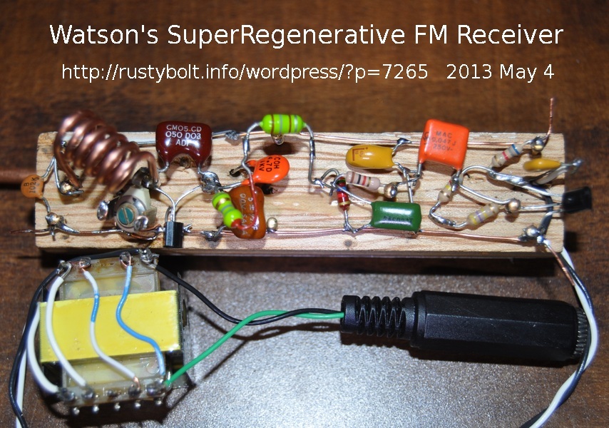
I stuck to the schematic, with the following differences (left to right). The 3.9k, 1 nF and 5 turn coil were the same. The “beehive variable capacitor” he used was not available, so I used a ceramic variable capacitor. The MPF102 with the 5 pF capacitor across it were the same, as was the 5 pF to ground. I changed the 5 pF antenna capacitor to a 4.7 pF, so really no difference. The 4.7 uF bypass capacitor was increased to 47 uF and I used a tantalum cap.
The 100 uH choke was not a good choice because the SRF (self resonant frequency) was below 88 MHz, so I used a 5.6 uH in series with a 180 uH. I used the 5.6k resistor but reduced the 10 nF in parallel to a 5 nF for a little bit more high frequency audio. I used a 1k instead of the 820, again no real difference. I used a .047 uF coupling capacitor, a 2N3904 and a 6.8k, all the same, but the collector voltage was too low with a 330k, and it had to be increased to 1.3 Meg to get the collector voltage up to 4 volts. I added a 0.1 uF to the output to block the DC, and connected all four windings of a 600 ohm transformer in series which is supposed to be 9600 ohms, and I connected a 150 ohm earpiece across the winding at the bottom, closest to ground.
For the antenna on the back, I held a foot long copper tube to the wood with three screws and the lead from the 4.7 pF capacitor passes through a hole in the wood to under one of the screws. The supply voltage was 9V and the current was a whole milliamp. Well. actually 1.1 milliamps. Even so the earpiece can get loud.
Update May 5 – I took a 3 by 3 inch pine board and pounded a headless finishing nail into it, and then drilled a hole in the bottom end of the circuit’s wood so it could fit over the nail and the nail would hold it upright. I noticed that keeping my hands off of it helps reduce the drift off frequency.
I couldn’t tell which direction was minimum or maximum on the tuning capacitor, so I removed it and put in a 1 to 17 pF variable and a 5 pF in parallel. The variable has a clear plastic separator between the plates so I can see what position the plates are at, from fully meshed to all the way out. Now I know relatively where the capacitor is set at. And the 5 pF brought the minimum frequency down to well below 88 MHz, somewhere around 84 or 85 MHz. Now I can set the receive frequency to a point where the TV channel 6 would be, but there is nothing there so there is no interference from other FM stations. It will also tune well above 100 MHz, but this band is crowded so I’ll never need to tune it that high.
The bad thing is that the circuit needs 9 VDC. The exorbitant cost of 9V batteries has led me to build a 1.5V to 9V DC to DC converter, so I need to build one up for this circuit. But the circuit takes only a little over a milliamp, so the converter will have to be a real miser and take in only about 20 to 25 milliwatts, or about 13 to 17 milliamps at 1.5V. That’s a lot less than the typical Joule Thief. But it may be better to use a 1.25V rechargeable cell. I think a shunt regulator using a 9V zener may be the best way to go. I’ve had interference problems with these DC converters in the past, so it may require some effort to reduce the interference.
I’ve noticed that when I have this receiver near another FM radio, it causes interference when they are both tuned to the same station. This is a result of the RF oscillations that are the reason for it being a superregenerative receiver. If I enclose it in a metal case, it might reduce the radiation somewhat, but I suspect that most of the radiation is coming from the antenna, which cannot be enclosed. The solution would be to put a preamplifier between the antenna and the circuit. It would reduce the radiation a lot, but probably not eliminate it. It would also increase the sensitivity of the receiver. The distance from the transmitter is not very far so this preamp is probably not needed for more sensitivity, but only for the radiation reduction. The question is do I want to do the added expense and effort to add a preamp. I think I won’t because this receiver will probably be tuned to a frequency below the FM band and should not interfere with the FM broadcasts as long as it’s kept a reasonable distance away from the other radios.
I’ve been searching for more receivers of this type to see if I could find one that has the preamp. Many of these receivers were designed to be used in the HF bands, 30 MHz and below, and due to the atmospheric noise, the preamp would not be needed since all it would do is increase the noise. So my searching hasn’t been fruitful. More later. I still have to think about the transmitter.


where is the circuit.pls email me.
thank you
I put a link in the blog, perhaps you didn’t read it. Here it is again.
http://www.youtube.com/watch?v=tbKffpfe9_s