I found some LED lights on eBay for under 6 dollars U.S. with free shipping. They’re shipped from Hong Kong, so it will take a few weeks to get here. They said sometime around the 4th of July. Wow! Instead of lighting up firecrackers, I’ll be lighting up LEDs!! They call these corn cob lights because, well, they look like a corn cob.
Speculation… (skip down to the update for the real truth)
As can be read in the link, they have 44 LEDs, so if all of them are in series, the total voltage would be 44 times 3.2 volts, or 140.8 volts. This would be fine, since when 120VAC is rectified and filtered, the voltage comes to 120VAC times 1.31, or about 169 volts DC. There would need to be a series resistor to drop the 28 volts difference. Assuming that the LED current is 20 mA, that would be 1400 ohms. However, if there is a capacitor in series with the LEDs, the voltage drop can be across the capacitor. This also reduces the heat dissipation in the light bulb because the capacitive reactance is not resistive, it’s reactive.
However, another inexpensive LED light that I have opened up has a switching power supply to give about 30 volts to the LEDs. The LEDs are not all connected in series, but in series-parallel. So I cannot be certain until I receive the LED lights and examine them more closely. That’s another way of saying that I’ll have to take one apart to see. Heh-heh.
I looked at the pictures in the link, and I saw that there were six sides, each with a flat panel of 6 LEDs, plus 8 more LEDs on the top end, for a total of 44 LEDs. This 44 number seems to limit the number of possible combinations. These could be divided up into two series strings of 22 LEDs each, with both strings in parallel. The division would be three panels of 6 LEDs each, plus four of the 8 top end LEDs. Thus 22 LEDs times 3.2V per LED would be 70.4 volts DC. I cannot see how it could be divided up into four series strings of 11 LEDs each, because it would require part of a panel, and that would make it much more difficult. I’m not saying it can’t be done, however it’s difficult from a wiring perspective. Another would be 6 panels of 6 LEDs each, and 6 of the 8 LEDs on the top, for a total of 42 LEDs. But the remaining two LEDs would not be included, so this does not seem to be a possible combination.
Another factor that’s in favor of all 44 LEDs in series is that this does not require any active devices. All that’s required is to rectify, filter and limit the current. This is very simple and very cheap, too. And since the lights are very cheap, it’s a strong indicator of this configuration
Ok, so it seems that easiest one would be all of the 44 LEDs in series. The circuit that I come up with is a capacitor in series with the AC input of a bridge rectifier. After the bridge would be a filter capacitor, maybe 22 or 47 uF at 200VDC. Then the 44 LEDs would be in series across the filter capacitor. What would value the series capacitor be?
Earlier I gave the value of 1400 ohms. At 60 Hz, I calculated that it would be 1.895 microfarads. But a capacitor rated that value at 250 volts AC, and rated X2 for connection across the AC line, would be very expensive. Eliminating the X2 rating would save money, but it would be less safe. The inexpensive night lights and similar AC powered devices do this all the time. But still, the 1.9 uF capacitor would be large and somewhat expensive. BTW, there usually is a high value ‘bleeder’ resistor – like 470k – across the capacitors to bleed away the charge when it’s not plugged in.
Another possible way to power the LEDs is with a transformer. If the panels had their LEDs divided onto 11 groups of 4 LEDs in series, and these 11 were connected in parallel, the voltage across them would be about 3.2V times 4 or 12.8 volts, and 11 times .02 amps would be .220 A or 220 mA. This would be easily obtainable with a small transformer, rectifier and filter capacitor. But there would (or should) be 11 current limiting resistors.
Many of the LED lights are not dimmable. The switching power supply they use tends to regulate the voltage, and this defeats the dimmer. The complex waveform caused by the dimmer could defeat the current limiting capacitor and cause problems.
The surface mount LEDs that I see in these lights are mounted on a circuit board that is laminated to a flat sheet of aluminum. and the aluminum gets quite warm when it’s lit. The first thing that I should do is measure the LED current. I suspect that the current is more than 20 milliamps. So far I’ve done a lot of speculation but I’ll have to wait until I see the guts to confirm any of this speculation.

Update June 19 – I received the corncob lights today. I was wrong: they shipped from New Jersey so it took only five days. I put one into the desk lamp and observed that it was truly a bright white – 6000 to 6500 degrees CCT acording to the label on the box. I also observed that it did not put out as much light as the 40W Cree LED light I’ve been using.
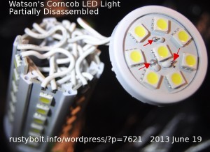
I examined the thin line where the top contacts the sides. While grasping the body, I pushed on the top with my thumb, and the whole top popped off. Didn’t take hardly any effort – very little glue, mostly just a friction fit. I was surprised at the number of wires inside (see the first photo). None of the wires I saw were color coded – they were all white. I looked down inside and I see two capacitors but I don’t see any inductors or other small parts.

One of the first things I noticed was that there was almost no metal at all in this LED light. No fins, no heatsinks, no PC boards laminated onto aluminum to keep the LEDs cool. This means that the light is likely to overheat due to the LEDs getting very hot.
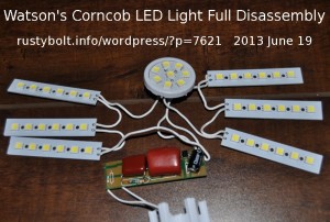
Four of the 6 side boards with 6 LEDs slid out freely when I pushed on them, but two were stuck. I examined them closer, and found that they had applied a drop of plastic solvent (acetone?) or super glue to two points where the top snapped into the base. Some of the glue got onto the two stuck boards, so I had to pry on them to crack loose the board from the base. Once I had all six boards loose, everything slid out easily, including the circuit board inside (see the second photo).
The circuit is simple. The AC comes in, one lead from the center contact of the screw base goes to the two large rust red colored capacitors, which are connected in parallel. The larger is 2.2 uF 400V, the smaller is 1.5 uF, 250V. The other wire from the threaded contact goes directly to the small black bridge rectifier next to the larger rust red capacitor. These two capacitors act as a current limiter. The output of the bridge rectifier goes to the black capacitor, which is 4.7 uF, 400VDC. The rectified, filtered and current limited DC at the right end of the board goes to two strings of LEDs connected in parallel. Each string consist of three of the 6 LED boards connected in series, and half of the 8 LEDs on the top. Below the smaller capacitor there is a 560k 1/4 watt resistor that discharges the capacitors when the light is not being powered.
WARNING! DANGER!
In the first photo I put three red arrows where the top has bare exposed wires that can be touched easily. Actually, all of the LEDs have bare leads that can be touched. These may have the AC line voltage on them. Many of the lamps I own use a two prong power plug, which can be inserted either way into the wall socket. This means that the either the center contact or the threaded contact of the screw-in base can have 120VAC on it. Depending on which way the lamp is plugged in, the base wire connected to the bridge rectifier could be 120VAC or neutral. If it is 120VAC, high voltage could be on those bare wires on the top. If you’re standing on a cement floor or in the kitchen or bathroom and touch the faucet and the bare wires, you will most likely get shocked.
On most of the CFL lights that I’ve disassembled, I see a 1 ohm metal film fusible resistor between the base contact and the circuit board. If something shorts out, the fusible resistor opens and protects the circuit from overheating and possible fire. This LED light HAS NO resistor or fuse for protection. This is inexcusable. All that they would need to do is make the PC board wire from the AC to the capacitor very narrow so that it would act like a fuse and open if the current became excessive. If the bare wires touch something that is grounded, the full AC line voltage could be across the bridge rectifier. This high current could cause a fire. So what we have here is a LED light that is both a SHOCK and FIRE HAZARD. This is a WARNING!
I measured the voltage from the three bare wires on the top to the ground pin of the power outlet. I got about 50.4 volts AC, which may not be deadly, but is dangerous and also could be a fire hazard.
Update Jun 20 – I am continuing this blog with the blog dated June 17th. I discuss the results I got when running the corncob LED light at various AC line voltages.
I have made some lights with this circuit, works well. But the one you have is missing an inrush resistor or small NTC, I used 100 ohm 1w. The capacitor is from the filter section of old computer monitor. X2 is safer. Also needs fuse.
I forgot to mention that you can get X2 caps from the filter in a microwave oven, they range from .68uf to 2.2uf. Some have one but most have two caps.
Yes, you’re right. The capacitors connected to the AC line should be rated X2. What I can’t understand is why the nightlights and other small lights that I’ve opened up and examined do not have X2 capacitors. I wrote a blog about this, but I can’t find it.. probably because it was in my watsonseblog which is no longer. I will discuss the 100 ohm resistor in an update to the ‘continued’ corncob light blog, so check it out.