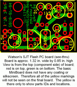
I have built a few dozen of my Supercharged Joule Thief Flashers using the PC boards that I designed and had made with ExpressPCB (schematic is in the link above and PCB picture is below). The circuit works okay with a fresh battery but when the battery gets low the light comes on solid, and that happens when the battery is below about 1V. My Blue Blinky does a better job of flashing. So I decided to use one of the SJT Flasher PC boards as a 1.5V to 9V DC-DC converter.
 When I designed the board, I added a few traces and holes for the Schottky rectifier ‘SD’ and filter capacitor (no label, just + and -), so the board has the room and is ready to work as a DC-DC converter. However it’s just a single transistor, there is no other transistor to control the base bias of the SJT. So I just removed the jumper ‘1’ and put a Zener diode in series with the blue LED. When the voltage gets up to about 8.6V, the LED and Zener conduct and limit the voltage. In other words it’s a shunt regulator that wastes the excess power in the LED and Zener. But because it’s a Supercharged JT, it only draws about 23 mA from the 1.5V supply.
I used a 1N5817 for the Schottky diode, a 470 uF 10V for the capacitor, and a 5.6V, 1/2W Zener. The output is taken across the LED and Zener. The transistor was a S8050, and the 4u7 capacitor and 150k were removed and replaced with a single jumper.
When I put a 3600 ohm load (about 2.2 mA) across the output, the voltage dropped from 8.6 to 8.2V. The supply current remained at 23 mA, — no change. The frequency was about 116 kHz.
Since this circuit draws a constant 23 mA from the single cell, it’s not a good choice for powering a DMM or other meter that might be left on for several minutes. It would be a good choice for a crystal tester, light meter or Gate Dip Oscillator, which are used for only a short period, maybe less than a minute. There are some gotchas when the circuit is used for a radio. See my earlier blog on powering the superregen receiver.