default

2013-06-07 Remote Control Extension

DSC_0368S2I’m not sure why I haven’t dome this before.  Actually, I have, but just not with a remote control.  Perhaps it’s because I wouldn’t want to damage the remote control.  But this time I bought some cheap GE remotes on Amazon for six bucks apiece, so the loss if I damaged one would be minimal.

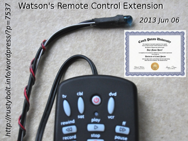
What I did was put a 16 inch (406 mm) extension on the IR LED of the remote control.  That sounds sort of like an oximoron, doesn’t it?  A remote control itself is an extension so why would I want to extend an extension?  I had some back pain, but Vicodin took care of most of that (don’t worry – it’s a prescription).  But when I grabbed the remote and held it over the top edge of my laptop screen, I felt a twinge of back pain, so I decided to do it.  It worked really great.  So great, in fact, that I awarded myself a Doctor of Couch Potato degree from Couch Potato University.  Now I can go around to my friends and tell them that I’m a master at making your remote so easy to use that you’ll never go back to the conventional remote again.

What I Did

I popped open the remote with a small screwdriver.  I had to get it started on one corner and force something else – I think it was a pen tip – into the slot, then move the screwdriver to a new spot.  Finally the case popped open.  I removed the PC board and unsoldered the IR LED, making a note of which way it went into the PC board.

I cut off a 16 inch length of 24 AWG zip cord from a speaker wire or wall wart, I forget which.  I suppose it could be longer, but I haven’t tried anything longer yet.  The zip cord has one conductor marked with a stripe, which I decided would be the negative or cathode lead.   I stripped off the ends and soldered them into the holes on the board, making sure that the striped lead went into the hole where the cathode was.

I separated the leads of the other end enough to slip a 3/4 inch (20 mm) length of heat shrink tubing over them.  I soldered the striped lead to the cathode or lead with a flat spot.  I shrunk the tubing over it, then did the other lead the same way.  Nice job, looked really pro.  I reassembled the control, and tried it out.  Oh, yeah, I had to reprogram it because the batteries had been removed.  I tried it out on the TV and it worked great.  Now I had to think about how I wanted to mount the LED.

I cut off a 16 inch length of stiff steel wire, I think it was 19 gauge.  It’s easy to bend, but holds its shape well, so I can point the IR LED at the TV and it will stay pointed there.  I bent a “hairpin” loop about 3/4 inch (20 mm) long on one end.  I cut off about the same length of heat shrink tubing, large enough to go over the IR LED.  I shrunk it over the LED and hairpin loop as can be seen in the photo.  One other thing I might do is put some hot glue or silicone seal into the hole where the wire comes out of the control.  This will help take the strain off the wires and PC board if somehow the wires get pulled.

On  the other end of the steel wire I bent a loop.  I then clipped the loop to the thin desk edge with a binder clip.  It holds it tight so it doesn’t fall.  I bent the steel wire so that the IR LED was aimed right at the TV’s IR sensor.  Now all I have to do is push the remote buttons while it’s lying on the desk,  Man, I sure am a couch potato, but.,,  No pain, no strain!

One has to use one’s imagination here a bit and come up with a method that does the job, doesn’t damage the furniture and is esthetically acceptable.  For my other LED lights, I’ve fastened the stiff wire to a spring clamp with wire ties or a screw-on hose clamp.  Even electrical or other tape will work in a pinch – no pun intended.  I’ve also used small C clamps to anchor the stiff wire to the furniture.    On one lamp I made I used a five pound barbell weight I picked up at a yard sale.  I drilled a hole in it and tapped the hole, then screwed a decent sized screw and washer into it to hold the stiff wire firmly.

In this remote control case, the IR LED is so small that it could be extended further and taped to the furniture so that it’s pointed in the general direction of the TV, and it should work.  Or how about this?  Just tape it to the brim if a baseball cap, and wherever you’re at, it will be pointed at the TV as long as you’re watching it.  Cool, huh?  What’s that silly wire hanging from your baseball cap?  It’s my IR remote control, silly!  Heh-heh..

Back to taking pain pills…

Update Jun 10 – I took a second GE remote control apart and unsoldered the IR LED.  I soldered in a 6 inch (15 cm) length of stranded twisted pair wire, long enough to be flexible and have a RCA jack on its end.  I installed that RCA jack, which allows me to connect an extension cable of any arbitrary length, or no length at all.  I then reassembled the remote control, with the short cable hanging out of the hole where the LED had been.

I soldered the LED onto another short length of the same twisted pair, and soldered the other end of the twisted pair into an RCA plug to match the jack, making sure that the polarities match.  Now I can plug the IR LED into the jack and use it similar to the first one, with an extension length of about a foot.  Or I can separate the plug and jack and insert any length of cable with a RCA plug and a RCA jack on the ends.  I can move the IR LED many feet or meters  from the remote control itself.  I will have to try using this setup in various places away from the TV.

default

2013-06-06 DC-DC Converter For DMMs

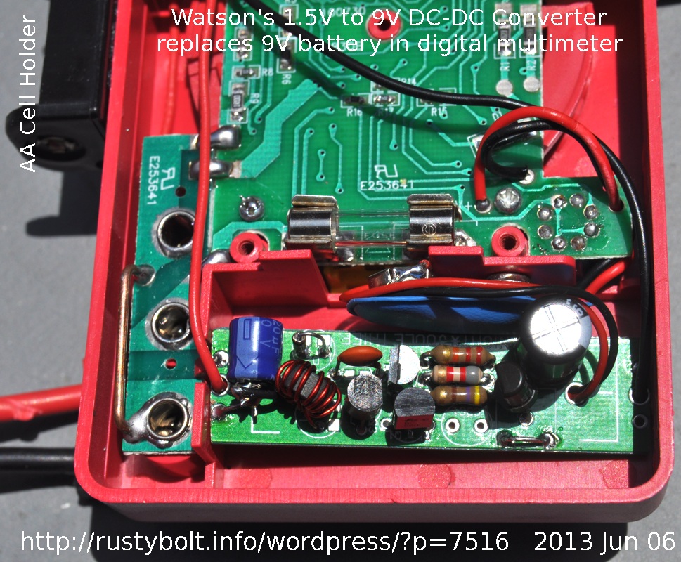
DSC_0355S3I’ve blogged this project more than once in the past, (and here too), but I didn’t follow through with the circuit completed and installed in a DMM.  Well, I finally got my act together and on the road, and finished the first working 1.5V to 9V DMM power supply.

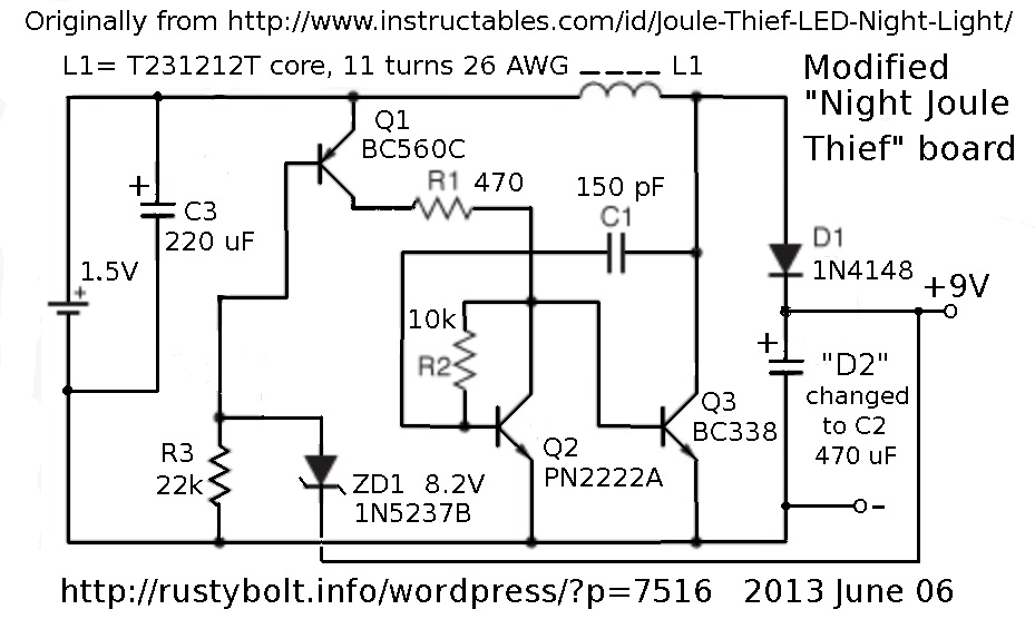
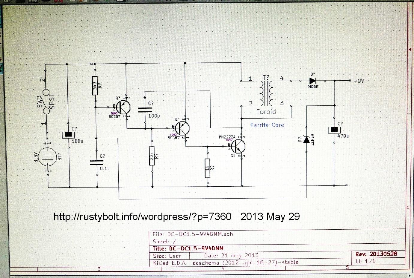
I thought about it and concluded that since I have a bazillion Joule Thiefs from previous experiments, I could use one of them to be the basis for this DC to DC converter.  After considering various circuits, I came to the conclusion that I could use Aki Sadoi’s “Night Joule Thief” circuit for the project, after making some modifications to it.  Information about the PC board is in the Instructable and on his website.  I purchased the bare PC board.  The parts values I used are shown in the schematic.  I did not have to drill any holes in the PC board.  Refer to the attached photo (click on it more than once to enlarge).  I had to sand down the ends of the PC board to get it to fit into the battery compartment.

DC-DCconv-NIGHTJT-09This circuit is ideal for the DC-DC converter because it has a third transistor that is used for control of the converter.  When the voltage gets to 9V, the Zener conducts and turns this transistor off, and the converter cuts back on battery current, so when there is no load, it draws only about 5 mA from the single 1.5V cell.  As the load increases, the 9V drops, the zener stops conducting and this transistor turns on and supplies more current to the converter.  At maximum load, which is about 5 or 6 mA at 8.5V, the converter is drawing about 70 mA from the battery.

The DMM draws only a few mA on most  ranges, so the battery only has to deliver about 10 or 20 mA.  When the DMM is set to the resistance measuring ranges, especially the 200 ohms range, the 9V current goes up to 5 or so mA, and the battery has to deliver about 60 to 70 mA.  The AA cell I’m using should last a long time, but the current is low enough that a AAA cell will work.  I did not include an On/Off switch in the battery lead, because I plan on removing the cell or I will put a small piece of plastic between the cell and the contact when I’m not using it.  A small switch is recommended.

I replaced the ‘upper’ LED with a 1N4148 diode which rectifies the pulses, and the second LED instead is a 470 uF capacitor (black one on the right) that filters out the high frequency pulses.  I show an 8.2V zener in the schematic, but I chose to use an old transistor instead.  The emitter to base junction on most silicon transistors breaks down or zeners at about 7 to 9V, so it can be used as a zener.  I had to try a few transistors to find one that broke down at about 8.4V, but since this can damage the junction, I clipped the collector lead off so that it could not be used as a transistor in the future.  I have not tried the 8.2V zener.  I did try a 6.8V zener in series with a red LED, which gave an output voltage of about 8.5V, a little on the low side but it worked okay with the meter.

The CdS photocell and VR1 are not needed, and were left out.  I put a 220 uF capacitor across the battery (blue one on the left).  I show a 10k for R2, but I used 8.2k.  This resistor has to be low enough to turn Q2 fully on, so that it is fully saturated and keeps its collector voltage well below the 0.6V that will turn on Q3.  Q3 could also be a BC337-25.  Other transistors may work for Q3, but it has to have very low saturation voltage at high currents.  The BC547 and 2N3904 are not good choices for Q3.

The T231212T core was from Surplus Sales, and cost about 25 cents U.S.  The core can be larger, but I chose a small one so it would easily fit into the battery compartment.  I wound 11 turns on it, but the number is not critical, 10 or so will work okay.  28 AWG (0.3 mm) wire should work okay, too.  Just try out your own hand wound coil.  If yours doesn’t seem to put out enough current, remove some turns and try it again, to see if it helps increase the current.

You don’t have to wind your own core; you can use a 100 uH choke instead.  The toroid has less electromagnetic radiation than a choke.  I didn’t experience any weirdness in the meter, but it could happen if the meter picks up interference from the converter.  That’s why I used the large 470 uF filter capacitor.  If interference is a problem, it may require that the 9V is filtered with some RF chokes, and/or use of an EMI suppressor sleeve.  With the parts as shown in the schematic, I measured the frequency at about 150 kHz, but it varies somewhat with the DMM current.

I drilled two holes through the case and ran the battery holder wires through them, then I glued the holder to the case with clear silicone glue.  Hot glue might work okay, too.

I have a few more bare Night JT PC boards, and I’m going to get another one or two working, maybe this weekend (June 8-9). I think I’ll try to use a 100 uH choke instead of a toroid.  I’m just trying to get a feel for what to do and what not to do.  After a few builds, I usually find out if and where any weirdness might be.  Then I can make modifications to get a circuit that is stable and works good.

Addendum – One other point about the Night JT circuit is that it uses a NPN for Q2.  This has an advantage – or a disadvantage depending on how you look at it – that it limits the maximum current that can be drawn by the base of Q3.  I think this is why the circuit would not go above about 70 mA when the load current is at maximum.  In the case of the LED, it would limit the maximum LED current and brightness,  But in this case, it prevents the circuit from drawing excessive current from the battery.

If this feature was sacrificed, this Q2 transistor and R2 could be eliminated and the bottom lead of R1 connected directly to the base of Q3.  Then C1 would be connected to the base of Q1.  This is the typical two transistor “JT” circuit seen in many places on the ‘Net.  The R3 10k resistor would then be split into two resistors and the zener diode connected to the ‘center’ or middle leads of these two resistors.  I have yet to try this configuration, though.

Back to experimenting…

More in my blog on the second one I’ve built.

default

2013-06-04 Error – Monkey Business

Transistor2of6InternalError(Youtube)I was watching the PBS series “Transistor” on Youtube and finished the first one (1/6).  It’s the history of the transistor.  I clicked on “Transistor 2/6” and I got this rather humorous error (click on it more than once to enlarge).  It seems that there may be some monkey business going on?  Or perhaps it blew a transistor!!

default

2013-06-01 New LED Light Bulb Competitor

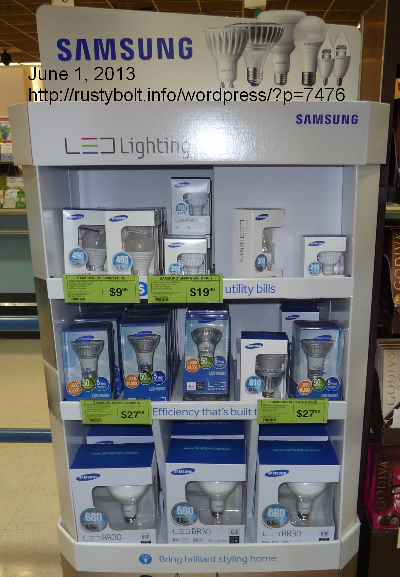
P1030620S2I went to the Antique Telephone Collectors Show today, and on the way home I stopped off at Fry’s to get a few cables.  They had micro USB cables for $1.99, so I bought all three that were left on the shelf.  On the way out, I saw this display in the line at the checkout.  It looks like Philips, Cree and others now have a new LED light bulb competitor.  Samsung is obviously not a new company, and has enough clout in the manufacturing and sales to be a serious competitor.  I’m just curious to know if they’re just remarketing some other maker’s LED lights.

Back to Raspberry Pi’ing.

default

2013-05-29 Electronic Transistor Turns 50

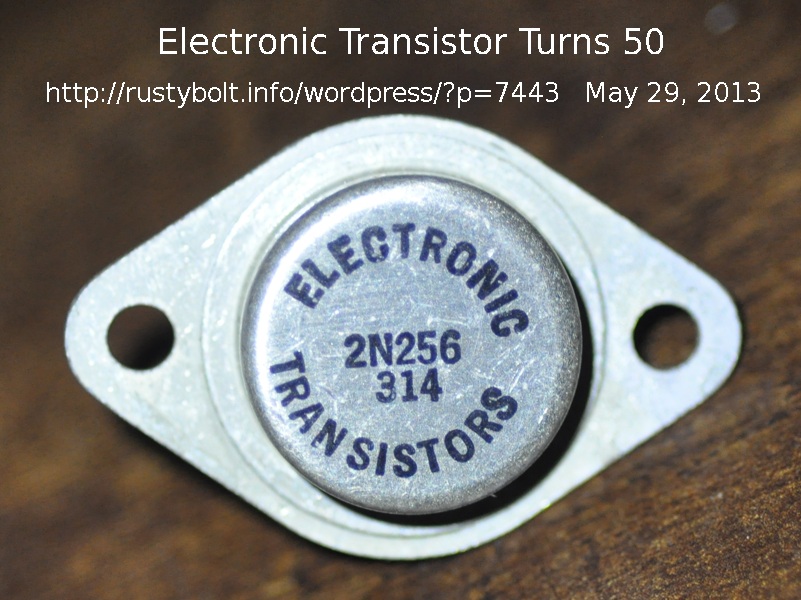
DSC_0295S2The photo is of a 2N256 germanium power transistor made by Electronics Transistors.  The “314” date code means that it was made during the 14th week of 1963.  So this transistor turned 50 years old sometime during early April.  I haven’t tried to hook it up, but it’s just cool to think that if it does work, it’s been fifty years since it was born and it’s still working.  That is more than could be said about a lot of other things especially electronics stuff.

default

2013-05-27 2N560 Antique and Unusual Transistor

DSC_0294S3

Click on photo more than once to enlarge.

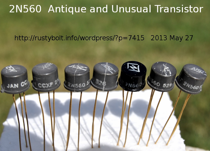
These 2N560 transistors are the only ones I’ve seen with plastic for the standard TO-5 case, which is usually metal.  The size and shape is identical, even down to the little tab that sticks out.  According to the Motorola Semiconductor Data Book (1969), the specifications are:

2N560 Silicon NPN

Pd@25 deg. C (ambient): 500 mW —  Tj: 150 deg. C

Vces: 60 Volts   hFE: 20 min @ 100 mA

Vce(sat): 0.5V @ 10 mA

And there’s nothing else given.  The NSC on the top apparently means National Semiconductor Company; the black one has a different logo, but I assume that it’s the same company.  The JAN CCXP before the part number means that it has been tested according to military specifications.  I measured the gains of the transistors and they varied from a low of 19 to a high of 93, with some around 30 to 50.  My guess is that time has taken its toll on some of them and caused some deterioration in the parameters.  I checked the specs for some other early silicon transistors, and it seems that this 2N560 is similar to the 2N335 types that were made by Texas Instruments back then and were used by some military equipment.

In the early 1960s most of the transistors being made were germanium, and silicon transistors were much more difficult to manufacture.  But the silicons were much faster than the germaniums, so eventually the germaniums were replaced by silicon and it’s very rare to see any germanium transistors used today.  But even though this transistor is silicon, the transistors made today are far better, especially when it comes to the current gain.  A typical transistor made today has a current gain more than ten times higher, 250 to 400 or even more.  And today’s transistors can go to more than ten times higher in frequency, too.  And with automated equipment, today’s transistors are much, much cheaper, probably a hundred times less expensive than back then.  The cost of a military grade transistor was much higher than a commercial one, so I would imagine that these 2N560 transistors could have cost tens of dollars apiece.

default

2013-05-21 LED Macro Ring Light V Boost PCB

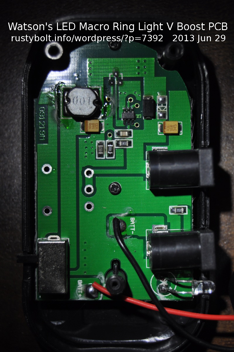
DSC_0397S2This is a photo of the PCB inside of the battery box of the LED macro ring light.  It has two AA cells, which can’t put out high enough voltage for the white LEDs, so the circuit on the PC board boosts the voltage.  This draws nearly 3/4 of an amp from the two AA cells, so it’s rather power hungry and the batteries don’t last very long.  The red and black wires go to the batteries.  Fortunately there is a jack for the 3V wall wart AC adapter, but that didn’t come with the ring light, it must be an optional item.

default

2013-05-20 Pill Bottle Exciter From Chris KD4PBJ

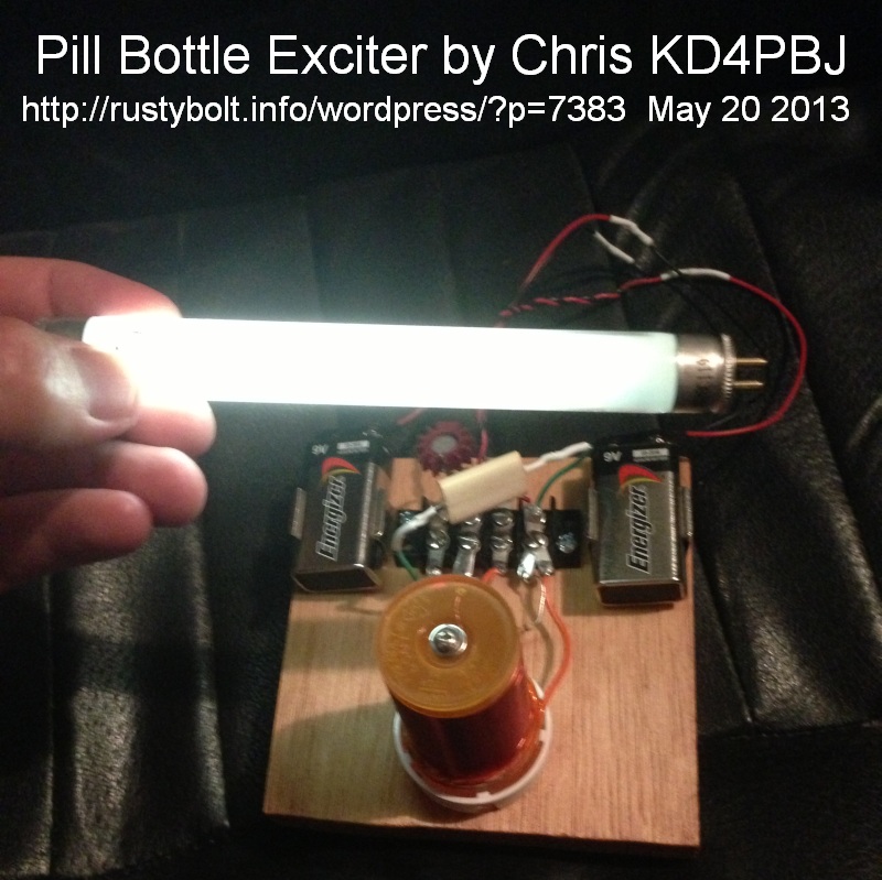
ExciterChrisKD4PBJphoto2S2I said I’d soon be posting another one of Chris’ KD4PBJ’s projects.  This is a pic of the exciter he built lighting up a small fluorescent tube.  It also lights up a CFL bulb.  Notice that it doesn’t use any wires, it just radiates a strong field and the light just gets excited!

Another trick that one can do is use what is called an AV Plug or Avramenko Plug to detect the field.  It’s really a half wave doubler.  This is an LED, capacitor and diode soldered together  and used as a probe.

default

2013-05-18 Audio Oscillator Uses hybrid Transformer

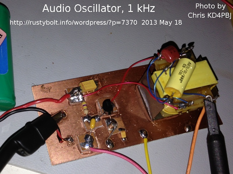
ChrisKD4PBJ-AudioOsc-photo-S3I’ve offered the hybrid transformers for quite awhile, and Chris, KD4PBJ, was the first to get some from me.  He constructed a 1 kHz audio oscillator (see the photo), with a .068 uF and .0068 uF capacitor in parallel to tune the transformer to 1.004 kHz.  I like the way he laid out the oscillator on a piece of copper PC board, with the squares of board glued to the ‘substrate’ as terminals to hold the component leads.  This is a very effective way to build a stable circuit for radio frequencies, since it holds the components firmly in place.

He also has another project that I’ll write up in a following blog.

default

2013-05-16 More on Kicad on the Raspberry Pi

This is sort of a continuation of my Raspberry Pi blog of a few days ago.

P1030606S2I spent a few hours last night drawing up a schematic in Kicad on the wee beasty.  It wasn’t easy.  I used the tutorial to get up to speed on the small stuff, like placing components and drawing wires.  The wires were especially difficult.  They are not anywhere as easy to draw as with ExporessSCH.  They want to do what they want to do, not what I want them to do.  There was more than one time that I had the program stuttering and doing weird stuff, like putting wires on top of wires.  It’s like there’s something not quite right about the algorithms that are supposed to be able to do the connecting.  When I mouse over and press G for grab, there is a dialog box that pops up asking to clarify if I want the component or the wire.  I choose the wire, but then when I try to grab the wire, the whole thing, component and wire, moves.  The whole idea of the clarify question was to resolve which one I wanted, but in the end it doesn’t resolve.

Needless to say, I’m not pleased that these problems are happening.  Then there is the problem of the colors.  I found the color preferences, and I changed most of them to black.  Now the schematic looks a lot better in my opinion (see screen cap).

Maybe tonight I’ll try to get the other parts of the program to do what they’re supposed to do: design a PC board.  But I think that’s a big step, and not as easy as it seems.

Update Jun 22 – I have officially rejected the Kicad program.  I spent several hours trying to get through the tutorial.  After suffering through a lot of frustration, it’s time to leave this user unfriendly program and go to some other more professional program.  I wanted the program to work with Linux, but I don’t see other programs that are for anything other than Windows.  I may go backe to ExpressPCB or something else like Eagle.  If anyone needs more specific details, contact me at my yahoo.com email address acmefixer.

© RustyBolt.Info/wordpress
CyberChimps