default

2016-05-21 Monocular Mount For Phone Camera

I went through something like this last year, and I looked around online for something to solve the problem.  But I came to the conclusion that I didn’t like almost all of them for one reason or another.  Usually it was due to cheap, flimsy plastic.  So I began again with the intent to solve the problem with something that I can make. So I’m showing a few ideas that I’ve come up with.  These are solutions to holding a monocular to the back lens of a cell phone camera so that it won’t move and will take a good photo.

The first one I came up with is to use a piece of a 1-1/4 inch white plastic ell or tee.  This will have to be sawed so that it has half of the ell or tee sawed off.  This will leave a half cylinder facing against the phone back, and a half cylinder sticking out so that the monocular eyepiece can be wire tied to it.  Looking at the letter L, it would be flipped upside down, and the back of the L would be against the phone back. The foot would stick out, to hold the eyepiece. Both back and foot would be a half cylinder. The phone back will also be tied to it with nylon wire ties.

Another idea is to use aluminum angle stock for holding the monocular eyepiece.  A 90 degree angle will hold any size cylinder with a wire tie or two. This angle stock may be held against the phone back with wire ties, but it may be best to make some form of clamp that grabs the edge of the phone so that the screen will not have a wire tie across it.

Another add-on may be to add a length of pipe to one end of the ell or tee. This is for added stability, and if the pipe is long enough, it could be notched so that the phone can’t slide down in the portrait position. Only half of the pipe will be glued to the tee or ell fitting, so they may need a screw and nut to keep them from separating.

The monoculars that I have are 8 or 10 power, so the whole assembly needs to be supported on a tripod. To the end of the pipe I could add a flat plate that has a hole tapped for the standard 1/4 by 20 thread for tripod mount. One problem is that this only allows for portrait, not landscape position. But I think the monocular cuts the picture off so it’s square.

I have to get some materials and start making something, with pictures for this blog.

I could extend the pipe down to make a monopod and add a few adapters to bring the diameter down to 3/4 inch, to save weight.

Update 05-25 – I used a 1-1/4 inch plastic T fitting I had. I cut it with a hacksaw right on the line where the two halves of the mold joined. Each half consisted of one side of the T and half of the vertical section. The half fits against the back of the camera with the side of the T sticking out where the lens is. This hole was too big for the monocular eyepiece, so I put several wraps of black electrical tape around the eyepiece. The eyepiece then fit very snugly inside the hole. It held the monocular in position but the eyepiece was not close enough to the camera lens. So I tried to pull the eyepiece out of the hole to remove some tape, by when I pulled, the eyepiece separated from the monocular! It doesn’t look like I broke it, but I’m unable to get the two pieces to fit together. The eyepiece has a mechanism that moves it to focus for different eyes, and this is actuated by turning the eyepiece a quarter turn. These mechanism prevents the eyepiece from just screwing back onto the monocular. So I will have to use another monocular or buy a replacement.

default

2016-05-16 Tape Wound Toroid Core From Surplus Sales

Long ago I built DC-DC converters using a toroid made with tape wound core. The cores were about 2 inches O.D. and we used regular 12 AWG solid insulated house wire for the primary windings. Even so, these cores vibrated a lot at several hundred Hz, making a screeching noise.

I saw some very small tape wound toroid cores for a dollar each from Surplus Sales of Nebraska. They have the part number 50B12-1D printed on them and Surplus Sales adds ICH- to the front of that for their Item number. The cores are 0.56 inch O.D. They were made by Magnetics. A link to the data sheet is in the advert.

I cut two lengths of 30 AWG wire each a foot (30 cm) long, and started winding them bifilar, together at the same time. As I wound, I measured the inductance with an LC meter. The inductance increased with each turn, until I got to 190 uH, but I still had enough wire for another turn, so I wound a thirteenth turn. The inductance jumped from 190 uH up to 10 millihenrys! So I removed that turn and it went back down to 190 uH. I thought that was really odd. I wound the thirteenth turn again and it went back up to 10 mH again. Strange.

Oh, well. I left it that way and soldered the rest of the parts to it to make a conventional Joule Thief. I used a 5 mm white LED, 1k resistor, BC338 NPN transistor and a 10 uF capacitor from plus to minus to bypass the ripple from the JT. The LED lit up brightly at 1.5 volts, and the frequency was 100.6 kHz.

According to the data sheet, the -1D suffix means the core is wound with 0.001 inch thick Square Permalloy 80 tape. The case is nylon.

These tape wound cores work great for a Joule Thief

Update May 27 – I bought a few toroid cores from China, and since the packages are in Chinese and they send no invoice or any documents, I really can’t tell who they were. But the cores are about 7/8 inch or 22 mm O. D. and are painted green. I wound one with 13 turns and I got almost 500 uH. So they are high mu, and should work good for a Joule Thief.

I decided to look for more, so my search came across some green cores on eBay. I ordered ten of these smaller ones, and they cost only 99 cents, shipping included. I think they are 9 mm O. D. I’m taking a risk, because they say nothing about the permeability, the cores could be made out of baked clay and painted green. I would expect that at this low price. I’ll just have to wait until June to find out. I received this in an email order confirmation, but I don’t know Chinese.

Seller:
深圳市艾姆诗数码科技有限公司
digital.mart899@gmail.com

default

2016-05-11 WW2 Bomb Flaw Changed The Course Of History

I watched the Nova episode Hitler’s Supergun on PBS tonight.  It was one of the most interesting I’ve seen.

During World War II, Hitler built a huge bunker in France to house superguns that could shoot explosive bullets 80 miles, to London.  The allies saw this on surveillance photos and targeted the huge underground bunker with regular bombs but the bombs were not powerful enough.  The British then designed and built bunker buster bombs.

But while they were building these bombs, the Americans came up with another idea.  They built a drone that could be remotely flown to France where the drone, packed with tons of explosives, would be flown into the bunker and detonated.

But the drone had to take off and get flying in the air by a regular pilot, who would then jump out and parachute to the ground.  The pilot who volunteered for this flight was Joseph Kennedy, Jr.  Joe was the oldest son of the wealthy Joseph Kennedy Sr., who was grooming Joe to be the next President.

While working with the drone, a junior officer found a flaw with the arming mechanism of the drone.  He reported this flaw to his superiors, but they ignored him because they figured that the designers knew what they were doing better than the junior officer.  This flaw allowed power to be applied continuously to electric solenoids, which were designed to only be powered intermittently, for a short time.  If the power was applied too long, the solenoids could overheat, catch fire and prematurely detonate the explosives.

The junior officer told Joe about this before the mission, and to jump from the plane as quickly as possible.  The mission began, and Joe piloted the plane into the sky, but before he could jump, the explosives detonated.  No body parts were ever found.

But before the drone mission, the British bunker buster bombs damaged the supergun bunkers so badly they were not usable.  Thus the drone mission was not even necessary.

Later, Joe’s younger brother, John F. “Jack” Kennedy became president of the U. S. and the rest is history, when tragedy again struck the Kennedy family.

I found it fascinating that such a strange and tragic set of interlinked events changed world history.

default

2016-04-28 Cancer The Emperor Of All Maladies

I bought the book and the DVD combination from PBS.  Right now I am reading the 500 page paperback, and I think it’s quite interesting.

Later, the author takes the tobacco industry to task for selling a nicotine delivery method. What’s worse, the tobacco firms are now selling cigarettes in other countries and the people are getting lung and other cancers.

Prevention

The researchers soon came to the conclusion that the best way to cure cancer was prevention.

George Papanicolaou was a doctor from Greece who got a job studying the menstrual cycle of the guinea pig. He examined cells, and later examined cells from his volunteer wife. Much later he found that he could determine if human cervical cells were normal or abnormally precancerous. He called this test the Pap smear.

STAMP
During chemotherapy, the first organ to suffer is the bone marrow, which makes the blood. Leukemia was cured by chemotherapy on the bone marrow. But other tumors needed a much higher dose of chemotherapy, but that would kill the bone marrow. So it was proposed to withdraw the blood producing cells from the bone marrow and freeze them. Then treat the tumor(s) with mega doses of chemotherapy, then put the frozen cells back into the body, restoring the bone marrow. This procedure was very expensive and the health insurance companies refused to pay, saying it was investigative and experimental. Over a period of years, it was found that the procedure was ineffective and very dangerous. The patients didn’t live longer or died from other causes.

I finished reading the book, and I thought it was very interesting, especially cancer from the genetic viewpoint. I highly recommend this book, The Emperor of All Maladies. I have not yet watched the DVD which I purchased at the same time, so I cannot say anything about its quality. But if it follows the book, and since it was made by Ken Burns, I would assume that it is very worthwhile to watch.

default

2016-04-18 Coil For FM Microphone Bug Transmitter

I’ve built an FM microphone bug or transmitter before, but it’s been a very long time since I wound coils for one.  Long ago I would wind too many turns on the coil and try it out.  The usual outcome was the bug would be transmitting somewhere in the low TV channels 5 or 6, which are from 76 to 88 MHz. just below the FM band.  I could see herringbone patterns on the TV screen.  Then I would use a ‘grid dip meter’ to find the signal and its approximate frequency.  Then I could remove a turn from the coil and repeat the process until the bug was transmitting slightly below or at the low end of the band.  I could then spread the coil windings apart or remove some pFs from the tuning capacitor(s) to get the frequency where I wanted it.  This used to be just above 90 MHz but then a station started using that frequency so I chose a lower frequency.

But nowadays there are no analog TV stations below the FM band, so the TV can’t find them.  And it’s just better to design and build the coil to be the right inductance before it’s put in the circuit.  The typical coil I used long ago was somewhere in the 0.100 to 0.150 uH range, with 125 to 135 a good value.  The problem is how to wind a coil the right diameter, length and wire thickness to be the right value.

The circuit I’ll use is a cheaper FM Bug circuit, a single transistor version. This does not use a microphone preamplifier transistor, it has the microphone connected directly to the RF oscillator. This means the microphone is not very sensitive and has to be close to your mouth. But it is simple and easily built.

There are a few changes I will make to the circuit. Since 9V batteries are so expensive, I will instead use four 1.5V AAA cells in a battery holder for 6V supply. I will change both 47k resistors to 22k. Also change the 220 ohm resistor to a higher value, 330 to 470 to save batteries. The 1 uF microphone capacitor is a bit too high, a better choice is a 0.1 uF.

One thing they forgot is a bypass capacitor across the battery. This important to the radio frequency. There should be a 0.01 uF ceramic disk capacitor from plus to minus, and keep the leads short. All of the leads should be short on the parts. The antenna is not needed for use within 30 feet or 10 meters of the radio receiver.

The BC547 is a good choice, but I have a lot of 2N3904 transistors, which is also a good choice. Just about any small, low power NPN transistor will work, such as PN2222A, 2N4401, 2SC945, etc.

COIL
image

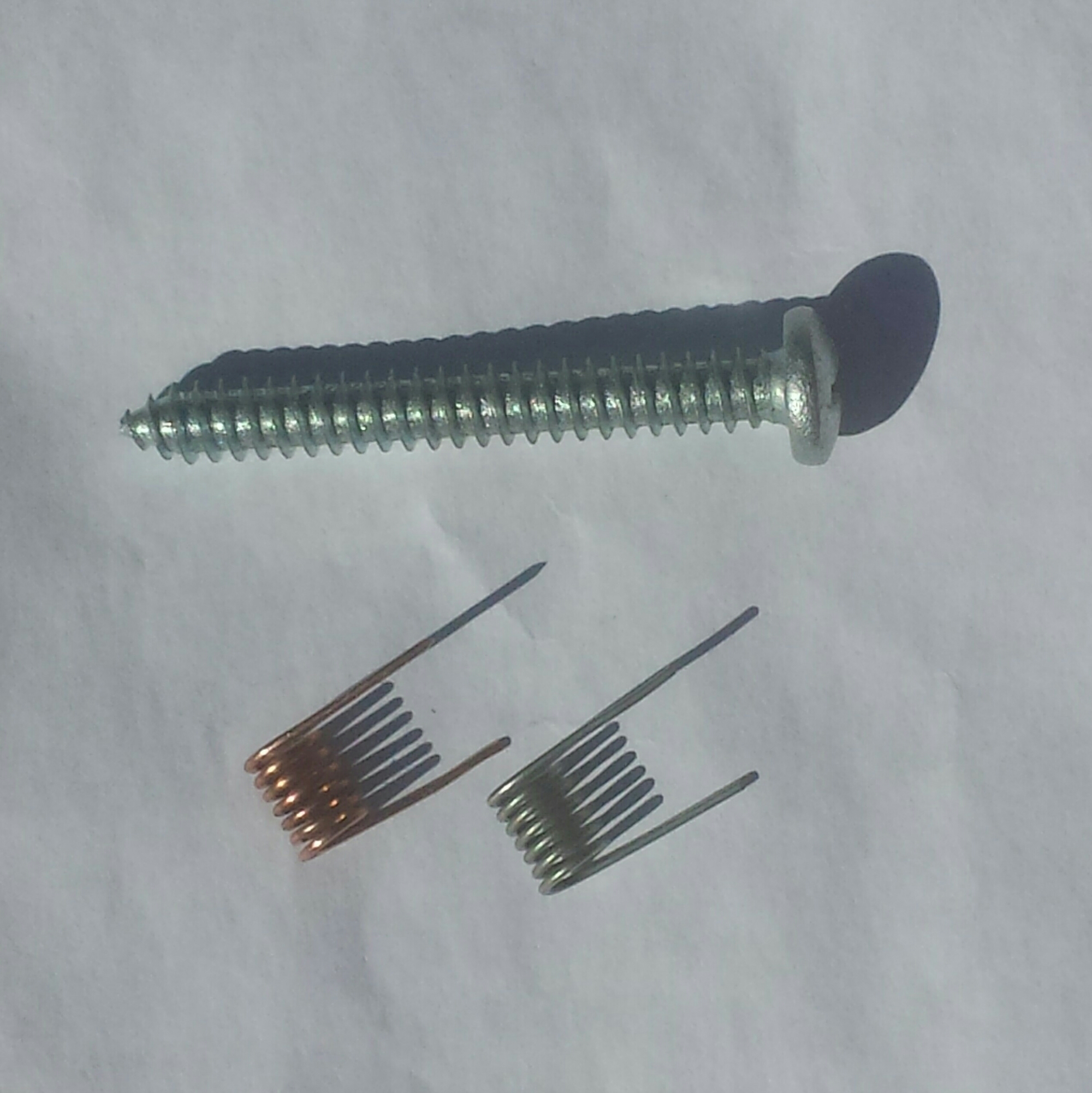
The coil has to use a short length of wire that is stiff enough so that it won’t bend while being handled. The wire I chose was 20 AWG solid wire which is 0.032 inch or 0.813 mm diameter. I chose 20 AWG because it is available at hardware or home improvement stores. This can be 2 conductor door bell wire or multiple conductor thermostat wire. This wire is usually bare solid copper and has insulation. The wire needs to be about 6 inches or 150 mm long. This will give a total of 6.5 turns.

The plastic insulation has to be removed. I used a wire stripper, but it’s important to not nick the wire. I use a utility knife or exacto knife and cut off a half inch of insulation so I can grab the copper wire with a long nose. Then I can pull on the insulation and it slides off the copper wire.

The wire needs to be wound around a form to give the coil a consistent diameter. I chose a large sheet metal screw as the winding form. The size of this screw is a number 14, and the inside or minimum diameter between the threads is 0.180 inch or 4.57 mm. The length of the screw was 1.5 inches but this can be any length as long as it can be held easily as the coil is wound around it. The thread pitch or threads per inch is not important because the coil will be compressed to give a coil length of 0.33 inch or 8.46 mm.

I started winding so there was about 3/4 inch of wire for the lead. After I wound the wire around the screw 6.5 turns, there was excess wire, which I cut off. Let me explain the difference between 1 turn and 1.5 turns.

|
O 1 turn
| The wire starts on the bottom left, loops around one turn and ends on the top left. The ends point in opposite directions.

O 1.5 turns
| | The wire starts on the bottom left, loops 1 turn (where it would be pointing upwards) then continues around another half turn where it stops bottom right. The ends point in the same direction.

I unscrewed and removed the screw. Then I squeezed the coil on its ends until it was 1/3 inch or 8.46 mm long. All of the turns were evenly spaced and were not close enough to touch. The coil looked evenly wound.

This coil is sturdy enough to keep its shape during circuit construction. Once the circuit has been built and the frequency adjusted to be on the low end of the FM band, the coil should be secured. This can be done a number of ways. The coils in radios made years ago were secured by inserting a small piece of foam sponge, and a few drops of melted paraffin or candle wax were dropped on it so that it prevented the coil from moving or vibrating. But today, any kind of thick glue can be used. Hot glue, silicone or epoxy will work, but whatever glue is used, it should not shrink as it dries, so the coil does not change shape. Paraffin or candle wax will also do the job. Another important thing this does is insulate the bare coil wire and prevent the turns from touching.

In the past, I have used a short length of soda straw inside of the coil, with glue to hold the coil in place. In this case the inside diameter of the coil is too small for a straw, but a small piece of plastic or similar would work. I have used wood in the past, but now I would avoid using it because in dry or wet weather wood shrinks or swells with the humidity changes. This could change the frequency a small amount. This also reminds me to tell about the rest of the circuit and its importance in frequency stability.

The circuit schematic shows the parts values but says little about these parts.

The transistor has some influence on the frequency, mainly with temperature changes, so it is best to keep it cool and not in hot sunlight or near any hot or cold air, where the temperature is not stable.

The resistors have very little influence as long as their leads are kept short.

The capacitors have a lot of influence, except for the 1000 pF capacitor from base to negative, and the .01 uF from plus to negative. Typical capacitors used are ceramic disk, and keep the leads short. The microphone coupling capacitor, a 0.1 uF, can be any type. Lead length is not important.

The remaining capacitors determine the frequency.

The capacitor across the coil has the most influence on the frequency. This is the tuning capacitor, and resonates with the coil at the transmitting frequency. For the frequency on 89 MHz the 0.125 uH coil must have 25 pF total connected to it. Of this total, the capacitor will be 18 pF and there will be approximately 7 pF in the transistor and the other capacitor connected across the emitter to collector of the transistor. This capacitor will have a value of 4.7 pF which is a small value often difficult to obtain. It can be made from two short lengths of insulated wires twisted together. Some glue or epoxy will help keep the circuit stable. It also is important that the circuit is mechanically stable so that the parts don’t move or vibrate.

There are many online aids to building this circuit. Some help can be found in videos found on YouTube or other similar websites. Some projects have good instructions on building this circuit. Do searches and read or watch some instructions to get an idea of what will help you to have good success with this project.

Note: Some kits and circuit boards have a PC board trace in place of the coil. This is typically a square or C shaped loop about 1-3/8 inch or 35mm across, and has about the same inductance as the coil, about .13 microhenry. Since this is a part of the printed circuit, it has the same inductance for each and every PC board made. This eliminates guesswork and the time needed to make the coil. The loop is very stable, as stable as the circuit board. I have built a similar coil using heavy 12 AWG bare solid copper wire. It worked good.

default

2016-04-16 Plastic Bag Heat Sealer

I was at Daiso, the dollar and a half store where everything is labeled in Japanese.  I saw a little gizmo that looks like it runs off batteries, and heats up a fine wire to melt and seal plastic bags.

I got to thinking about it after I left without one.  A few years ago I bought several thousand resealable plastic bags to put parts screws and other stuff in.  They work great.  The one thing I notice is that some parts with plated leads get tarnished, especially LEDs.  This is from sulfur and other pollutants in the air of So. California which has long been the smog capital.  So I was thinking that I should get one of these bag sealers and seal most of the parts in tarnish proof plastic bags and only remove them when needed.

Long ago I worked for a person who used a desktop model, and it was amazing how well it worked. It was very handy for storing items. We could take a piece of scrap plastic bag, fold it over and seal it on the two edges. I then cut off excess with a scissors. The bottom was where it was folded and the top was open, waiting for the parts. Any size or shape could be made. The sealer would overheat the plastic and cut it if it was squeezing the seal for too long.

I don’t think a small, hand held sealer would do a very good job, and it would waste batteries. I was thinking I should try to get one that plugged into the wall, and could seal a decent sized bag. I will have to look online to see if they are sold for a reasonable price. I found an 8 inch sealer with a spare element for $58, so I ordered it and I should get it next week. It says the only time it needs power is when it is sealing, which is saving a whole lot of electric power if it’s not like a soldering iron, which needs to be on all the time.

default

2016-04-05 Solving The Junk Call Problem

For both of my cell phones, I receive far more junk ‘spam’ calls than legitimate calls.  I have reported hundreds of calls to do not call.gov, and I’ve seen no letup in the number of calls, if anything it has become worse. I believe that the telemarketing co’s get my name from a list of homeowners, because I used to get a lot of calls for home improvement.

I installed the True Caller app and it has helped.  After a few calls, a spamming number causes True Caller app to generate complaints to True Caller’s centralized database, which then tells all other users that this number has been reported as spamming.  After the user blocks the number, no more calls get through. The spammers change numbers often, so it’s not fully effective.

I was thinking about this and more ideas and thought up a solution.  This solution depends upon public availability of the calling patterns of all phone numbers, probably by area code.  The first phase of implementing this solution is to finish making this database available.  It must be available in software readable format.  The database must be updated frequently, every 24 hours or a few days.  This is so that the second phase can pinpoint the spammers before they have a chance to change numbers.

The second phase is to develop software that generates statistics for the calling pattern of every number.  This includes the number of total calls, the number and percentage of incoming and outgoing calls, the number of calls incoming and outgoing that were answered successfully.

First off, if the software finds that the actual ANI number does not match the CallerID number, something is wrong or they are violating the law. It can be assumed that the number is trying to hide, and is probably used to spam.

Then if the software can compare the number with a list of inactive or disconnected numbers.  If a match is found, and the inactive number has a high volume of outbound calls, then it is being used to send junk calls, and should be labeled as such.

This software will use this information to determine if the number is making or receiving mostly inbound or outbound calls.  The software must compare the number with a list of legitimate numbers, such as notification services of pharmacies, schools, etc.  If the number is not getting or accepting incoming calls and not on the legit number, then it should be checked for a large number of outbound calls.  If it has, it should be assumed that the number is being used to send calls that are telemarketing.

Part or all of the processing can be done within the phone system.  The results can then be made available as a service.  Otherwise the user could develop an app for the smartphone that would do some or all of the processing, and act upon the results. Also, this information could be sent as additional fields in the CallerID data.

Further analysis will narrow down the many numbers that need to be blocked, such as a large group of numbers at the same location. This will have some implications for certain users, such as those who do legal cold calling. Nonprofits are one group. But many of these use volunteers who use their own personal phones, so they would be affected minimally. This system can be implemented as a pilot test in a smaller part of the country. Once the system has been tested and results are known, then widespread deployment can be done.

Update 2016 Jul 10 – I think a short term method may work okay. The telcos would forward an incoming call to a voicemail greeting. The greeting would play “Enter password” and pause for a few seconds, then repeat “Enter password”, then pause for a few seconds, then say “Goodbye” and drop the connection. During the time this greeting is being played, if any valid DTMF digit is received, the incoming call would be forwarded to the called number. This causes the caller to be more like a human, and requires that someone be listening to the greeting.

Another Idea
Instead of listening for a valid DTMF digit, the greeting could listen for the CallerID information. If the CallerID information does not check as a valid working number, then the call would be terminated.

Update 2016 Nov 22
I think it would greatly help complainants if the FTC’s Do No Call online complaint reporting system is made more user friendly. The FTC could create an app for doing this. The app would save the complainant’s cell phone data, such as number, IMEI, name, address, date and time, and it would grab the junk caller’s number. All this would be completed for the complainant when he or she reports a complaint. The app would require a captcha to make sure it’s a real human.

The FTC would require more servers, or some kind of regulation to require phone service providers to collect, accumulate, possibly process, and forward the data to the FTC.

I think the telcos will be resistant to helping the FTC. It is in their interest to get the junk caller’s business, and judging by the number of complaints from their customers, the telcos really don’t have the customer’s satisfaction in mind. I think that of they really did, they would have long ago added services to help mitigate the negative effects of junk calls.

Thinking about it, I don’t see why the FTC would have to do this app. Any company that makes apps for phones could add this feature.

More ideas to come.

default

2016-04-02 LED Light Ideas For Autos

I bought a few dozen 1 watt LEDs when they were on sale last year at Electronic Goldmine.  They go on sale periodically, for well under a dollar each in a package of 5.  A while back they offered daylight but recently they have all been warm white.

These are surface mount, so they are supposed to be mounted to a PC board for heat sinking.  But instead I glue them to an aluminum heatsink with thermal adhesive called ?.  It works good, the heatsink takes away the heat and I can run the LED at full power, but I usually run them at a half watt or so.

I thought I should come up with some ideas on how to use them in a vehicle.  Earlier this year I bought a reel of flexible strip LEDs that are made for 12 volts, and these can be cut to length on the markers so just about any length can be used.  But they are not as good for replacing incandescent lights in point sources as 1, 2 or 3 LEDs on a round heatsink.

My Civic is just a few years old, but it came with incandescents for the lights.  I’ve replaced some with kits I got on eBay.  But I want to make my own for a few lights that need to be replaced. 

The main reason I want to replace the old lights is that I have had at least three occasions where the mirror or dome lights have been left on, causing the battery to be run down after a few days and then the car won’t start. This again happened recently, renewing my interest in replacing them. By doing so, the LEDs take less current and don’t run the battery down as fast, and the LED lights dim to a very low current quickly as the voltage drops, hopefully stopping the battery from being drained fully.

My plans were to put three 1 watt LEDs in series for a supply voltage of about 10 volts minimum. But I would also have designs for 2 and 1 LED. The three LED design is simple; just three LEDs in series with a small value resistor to limit the current. The 2 and 1 LED designs may also use just a simple resistor, but then the light will eventually run the battery down to 6 or 3 volts. To prevent this, I can use other methods of limiting the current. One would be to put a Zener diode in series with the LED to drop more of the voltage. A 6.2 volt Zener and single LED will give the same design as the 3 LED light, with the same resistor. A 3.3 volt Zener in series with 2 LEDs will give the same design as the 3 LED light, with the same resistor.

I thought about using a current limiter circuit. This gives a constant current as the battery voltage changes. This is good for constant light, but I want the current to drop to a much lower value as the battery voltage drops. Below about 12 volts, the circuit current should drop to a minimum value just enough to keep it running. So for now I will use the resistor for this current limiter.

The resistor is chosen to give the maximum design current at the maximum battery voltage. The LEDs are rated for 1 watt at about 3.3 volts, which is about 350 milliamps with good heat sinks. I figure that 250 mA would be a good choice, at 15 volts. So for 3 LEDs, 15 volts minus 9.6 volts gives 5.4 volts. Divide that by 0.25 amp gives 21.6 ohms. A standard value of 22 ohms is chosen. Multiplying 5.4 volts by 0.25 amp gives 1.35 watts power dissipated. A 2 watt resistor should be used. Or two 1 watt resistors, or four 1/2 watt resistors could be used. Using three 1 watt resistors is okay, but three 1/2 watt resistors is too close to their maximum power dissipation, so I would reduce the total resistor dissipation to 1 watt in that case. If I multiply 5.6 ohms by 4, I get 22.4 ohms, and 1/2 watt per resistor gives 2 watts total.

I can do it with four 91 ohm, 1/2 watt resistors in parallel, giving 22.75 ohms. Or else use four easier to get 100 ohm resistors, giving 25 ohms total. If you have to have the few mA lost with 25 ohms, then put a 180 ohm resistor in parallel with the four 100 ohms, to bring it down to 22 ohms.

The resistor’s values do not have to be the same. It is also easy to add another switch to turn on only 1 or 2 resistors to give a low and high brightness choice.

So with this, we have the basic simple design for three LEDs, or 2 LEDs or 1 LED and a Zener diode.

MORE SOPHISTICATED

More complex, sophisticated designs can be used. Usually these are buck switching regulators. They do not have to be complicated. But these circuits don’t shut down when the battery voltage drops. One simple buck regulator is the Roman Black regulator, from http://romanblack.com. I found that this design does not start reliably with a load connected. If it does not start, it could damage the LED or burn itself up. If it does, it can fail shorted, putting very high current through the LED.

I also have a circuit from a 5V charger that plugs into the cigarette lighter socket. This circuit failed, so I’m not sure I want to use it! But it used a small transistor to pass a high peak current, so that may have been the reason it failed. I could use a higher power transistor to prevent this.

QS has a buck current regulated circuit at http://quantsuff.com. The nice thing is the current regulation. But I have found that you can buy circuits designed for powering LEDs from sellers on eBay or Amazon. These are adjustable for different LED currents.

NO INDUCTORS

One thing the typical buck regulator circuits have in common is an inductor or choke. These are more difficult to get than other components. I’ve thought about designing a circuit that doesn’t use an inductor. The circuit’s efficiency may be lower, but it still may be more efficient than a simple resistor. Another addition to design into this circuit is a timer. After a minute or so the light will start to dim and a pushbutton must then be pressed to add more time. The switch would be a three position switch: off, on and start timer. This circuit would be a simple analog circuit with a capacitor and resistor that discharge in a minute or so. I don’t see a need for a digital counter timer, but if a microcontroller is used somewhere else, it could be also used as a light timer. The pulse width could control the brightness.

default

2016-03-22 Thermo- and Barometer, Arduino Nano

My blog was down for a few days. The hosting svc had to consolidate its IP blocks and give some back to the RAR, so my rustybolt.info was pointing to the wrong IP.

I was looking out the patio door at the radiometer on the table outside, watching it spinning like crazy in the really bright sunlight we’ve had for a few days, and the thought occurred to me. Why not put a led pointed at the blades and count the pulse rate? The more light, the faster it spins. But at low light levels, sunset and sunrise, it doesn’t spin, so it can’t measure the light level.

The guys I correspond with homebrew their own thermometer and barometer with an Arduino. They add pressure and temperature sensors, a LCD, and the software, and they have a working thermometer and barometer. But a few years ago I bought several indoor/outdoor thermometers for a very low price from a surplus store, and they work OK as long as I put new button cells in them every year. And the barometric pressure isn’t that important. I’m really more interested in the wind speed and direction. And as I said, the insolation (solar radiation). The weather is pretty boring here, it hardly ever freezes, the temperature just gets down to 50 to 60 degrees at night and high 80s most of the year, except for a few weeks during the summer and winter, and it’s a desert, there has been so little rain. My gauge of how windy it is is to look out the window and see if the palm trees are bending. If it’s really gusty, I can see the water in the toilet bowl moving up and down as the gusts blow across the vent pipe on the roof.

I thought about the radiometer, and realized that all I really need is a solar cell and a small piece of glass that goes in a welding helmet, to cut the light down to let the cell operate in its linear range. Point them up to the sky and measure the cell resistance with the Arduino. Calibrate it with a light meter. The measurements can be spaced every few minutes, since the sunlight doesn’t change fast except during a storm.

Okay, now for the wind speed and direction. I looked at the anemometer wiki and I was overwhelmed by more than a dozen different ways to measure the wind speed. I’m guessing that eight directions of 45 degrees each would be good enough, or else 16 at 22.5 degrees each. The wind speed and direction change more rapidly, so they may have to be measured every few seconds or less.

So there are 5 things to measure. Pressure, temperature, radiation, wind speed, wind direction. A CMOS 4051 can multiplex analog signals onto a common input. Or does an Arduino already have enough inputs of the right kind to do the job.

Another consideration is adding a logging feature. Store the measurements and their date+time in a file, formatted for processing at a later time.

I looked at models sold commercially. They can be bought for $50.00 or less from Walmart and Fry’s. Some have a precipitation gauge, but like I said, it seldom rains here. Some cities or municipalities have most of the info on their website. About the only thing I can’t get online is insolation, and that’s easy to obtain with the photocell.

default

2016-03-18 Peter Builds A Tesla Coil

I received an email from Peter, who has planned on building a SSTC, solid state Tesla Coil. Peter gave me permission to post this email discussion to my blog. I have redacted some information for privacy reasons.

“From:”Peter Bergmann”
Date:Wed, Mar 23, 2016 at 5:31 PM
Subject:It´s alive!!

Dear Watson,

since I just can´t get the VN10KM mosfet I tried something else – Daniel 
Eindhoven´s Audio Modulated Solid State Tesla Coil V 2.0 and it works!! I´m only using 70V DC at the moment and
I´m yet getting a decent breakout (it´s 
designed for 325V DC).
See for yourself!!

L8r…”

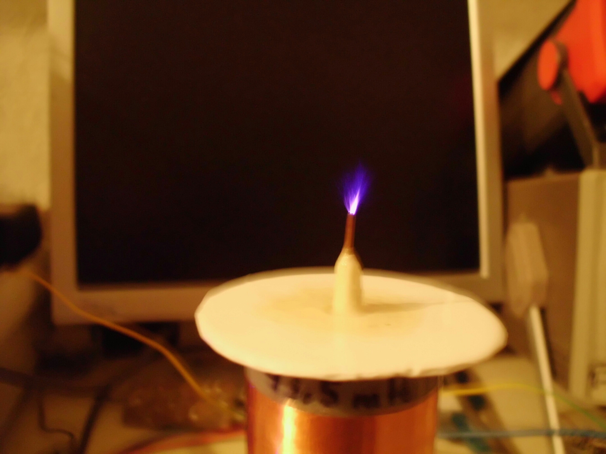
image

I kind of like that smell of ozone that TCs give off when they’re arcing!

UPDTAE

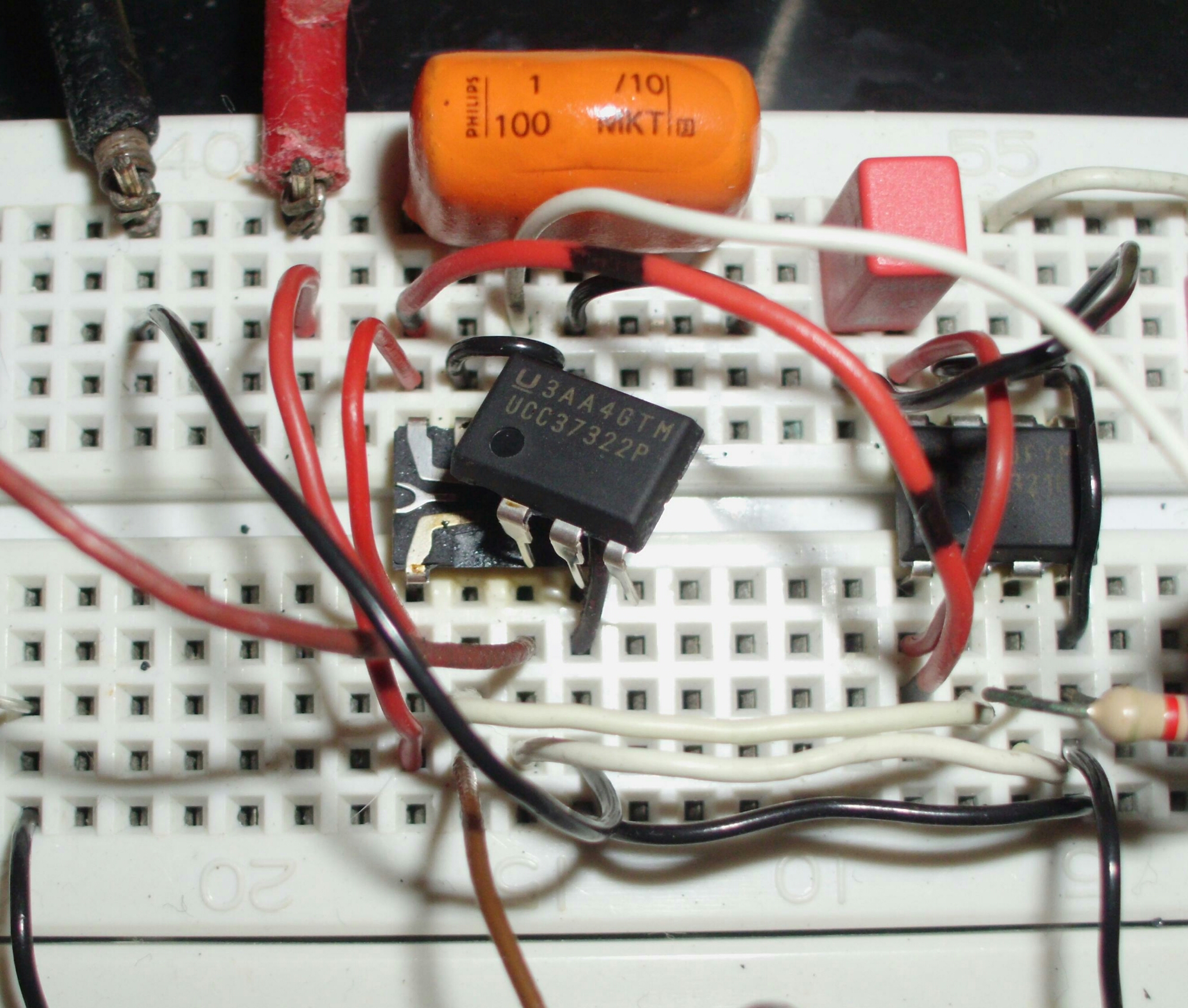
Update Mar 30 – I received more (not so good) photos from Peter, along with a video (can’t upload it yet) and a bit of text. I’ll continue after the photos.
image

Wow! I bet that made a nasty pop!

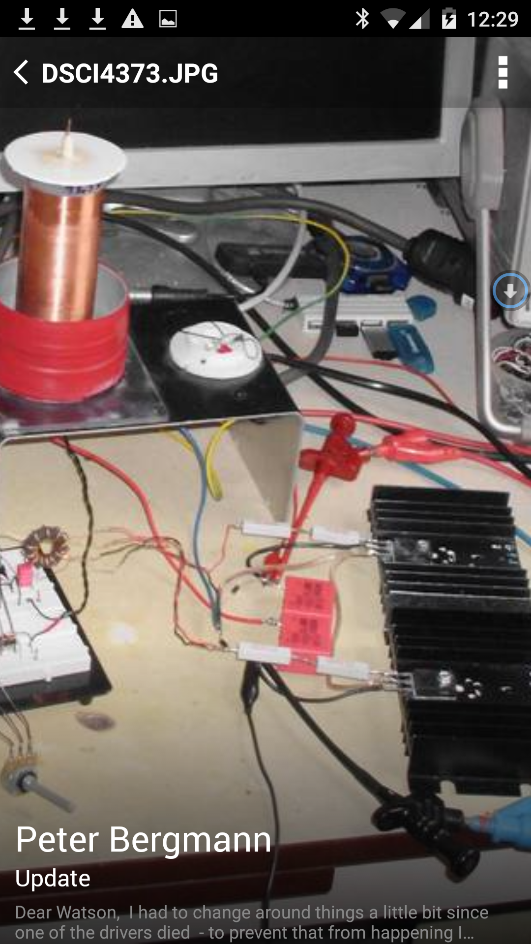
image

I enlarged his bench photo to show the power MOSFETs and driver transformer.

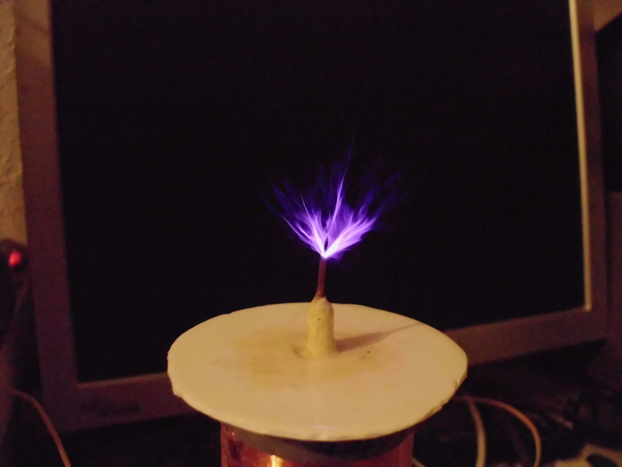
image

A big improvement over the first photo. I should point out that these arcs may damage electronic devices such as monitors and flash drives, so it’s best to keep them separated.

Okay, for some of my thoughts and guesstimates about what might have happened. The 2 MOSFETs require a minimum voltage on the gate to turn fully on. It’s best to have at least this much so that the MOSFETs spend as little time as possible between off and fully on. In this case, it’s possible to change the turns ratio on the driver transformer to change the gate voltage.

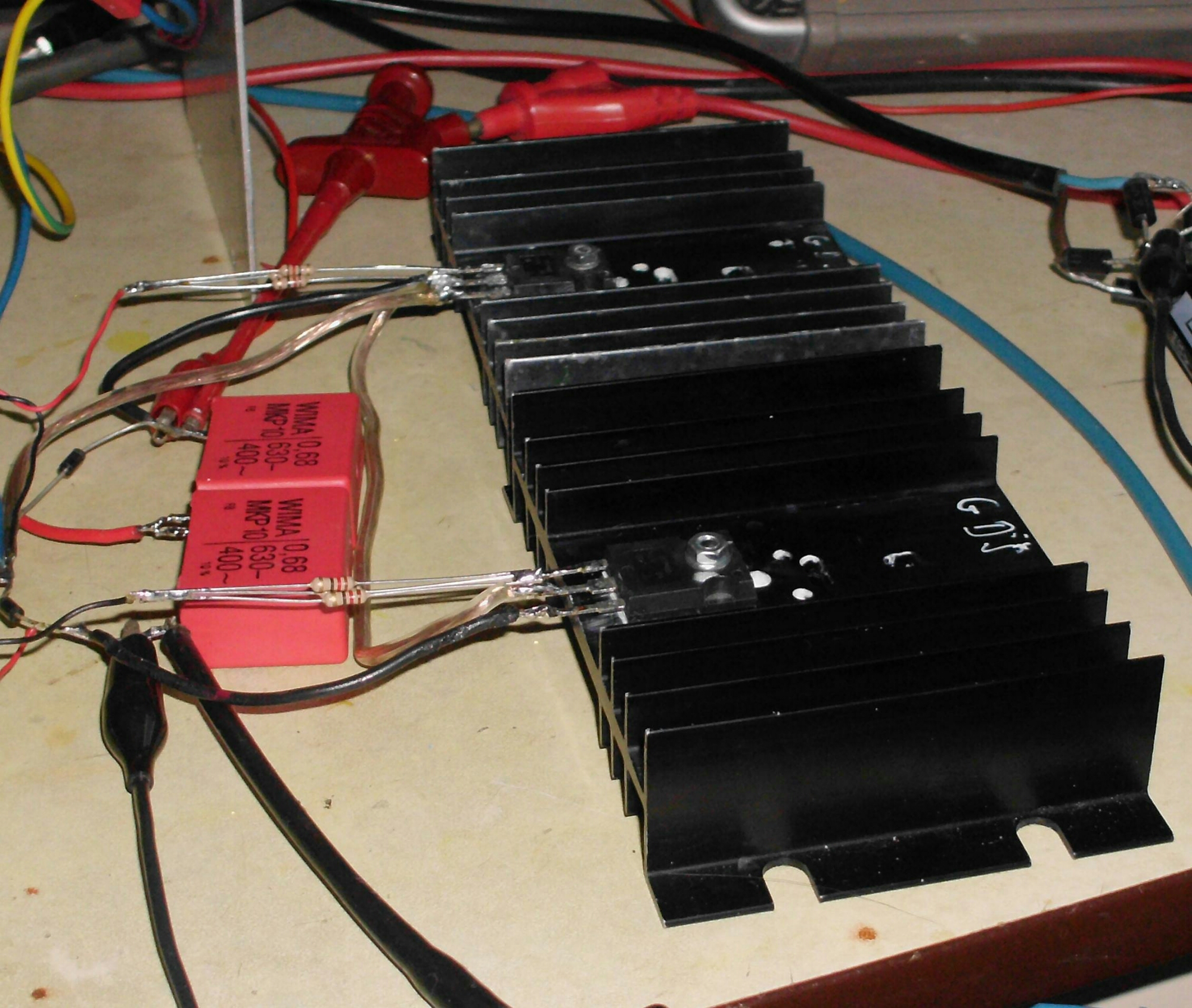
My guess as to what may have caused the driver failure. In the enlarged photo of the driver, I see two large wirewound resistors in series between the toroid and each gate. The wirewound resistors have a coil of wire which also has inductance. This L may be interacting with the C of the gates, making a series tuned LC circuit. These resistors should be noninductive, preferably carbon film, but not wirewound. If they get very warm, then the driver chip may be overloaded.

Due to the Miller Effect, some of the high voltage changes on the MOSFET drain goes through the capacitance and appears on the gate. This has to be overcome by the driver current. If the voltage fed back through the resistors to the driver chip exceeds the chip’s ratings, it can damage the chip. If the chip is rated to handle 12V supply voltage, I don’t think the reason it failed was because the supply voltage was too high. If the gates get enough drive voltage at a lower supply voltage, then why not use it, as long as the MOSFETs don’t get hot.

If you look at a 400 watt ATX switching supply, it has a small heatsink for the switching transistors, but it does have a fan to keep it cool. In fact, an old PC power supply would make a good SSTC because it has the on/off switch, line filter capacitors and inductors, bridge rectifier and electrolytic filter capacitors, and a fan and heat sink for the MOSFETs. Some boards have a TL494, which was used in Peter’s original schematic.

It might be a good idea to put a 15 volt, 1 watt zener in parallel with the driver output and common. The cathode has to go to positive, so that current flows through it only if the drive voltage exceeds the supply voltage, or if it goes negative. This is safety and protection for the driver chip – it’s not for performance.

Update Mar 31 – Peter sent a new photo of the MOSFETs with new resistors.
image

It looks to me to be three 12 ohm resistors in parallel, which gives 4 ohms to each gate. I think they should be better than wirewound resistors as long as they don’t overheat. This reminds me of something I should do. I should go to Harbor Freight, a discount tools importer, and buy an IR thermometer. With this, I can point it at a heat sink or resistor and get the temperature without touching the part, while it’s operating.

I built a DC-DC converter a few years ago that used a much lower power MOSFET. I used a 100 ohm resistor in series with the gate. I found that 100 ohms was too low, that it was best at a bit more, something like 120 ohms. I was surprised at how much difference that small change made. It was not difficult to find a 100 ohm trimmer pot. But Peter needs a trimpot with a very low value, only 10 to 20 ohms or so. I think I would use a 100 ohm trimpot in series with a 6.8 ohm resistor, replacing one of the 12 ohm resistors. Then it could be adjusted from less than 4 ohms up to about 6 ohms.

This is not a lot of adjustment, so some way has to be used to measure the coil’s performance. It’s convenient to measure the power supply current, even though it doesn’t tell me what the actual coil output is. But it’s very difficult to measure high voltage AC at radio frequencies. Another way is to put a CFL bulb near the coil, and measure the brightness of the bulb. The resistance of a CdS photocell in a dark room should give a valid relative CFL brightness. Instead, the CdS cell could be pointed at the arcs streaming out of the top of the coil.

Speaking of arcs, the small pill bottle exciter I made had a very feeble arc. So I went to Michaels arts and crafts store and bought some Styrofoam balls that are used for Christmas decorations. They were expensive for being almost nothing but air. I wrapped some bare copper wire around a 2 inch (50 mm) ball, then covered it with aluminum foil. I mounted this on top of the coil and it improved the arcs somewhat. The Styrofoam balls were also available in 4 inch (100mm) size.

If Peter’s MOSFETs are running cool, he may be able to put both of them on the same heat sink. Mounting the heat sink vertically will allow much more air to flow through the fins due to convection.

More fun in the next update.

Update 2016-05-03 – I received an email from Peter with a link to a short YouTube video of his SSTC in action. The arcs and sparks are impressive, much longer and thicker than earlier. But they are not as long as a TC with a sphere or ‘donut’ on the top. I think having one would help, but it’s up to Peter to experiment with one. The arcs and sparks are awesome the way it is.

© RustyBolt.Info/wordpress
CyberChimps