


2016-02-23 Joule Thief With Daylight Shutoff
I designed my Blue Blinky with a daylight shutoff, using a LED as the light sensor and an additional transistor to amplify the minuscule current that the LED puts out. This worked just great because there is the point across the timing capacitor where the current is very low, and it takes very little current to shut off.
With the continuously on Joule Thief, the bias current to the base goes through the 1k resistor, which is about 0.9 mA, which is a lot more than the Blue Blinky. Therefore the current is much greater and the LED and transistor must be amplified much more. This is done by Q2, a PNP 2N3906.
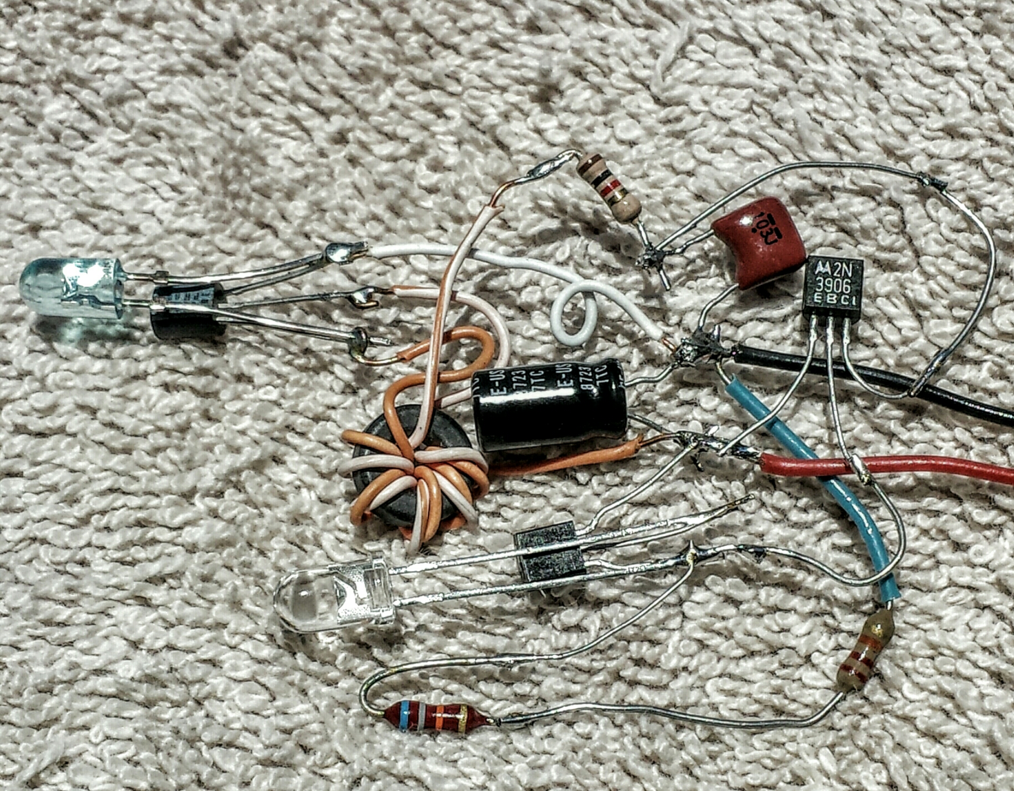
The Joule Thief is center and left. The light sensing LED is at bottom center along with the 2N3904 to amplify its current. Black and red wires are minus and plus 1.5 volts respectively.
I experimented with the resistance from the 2N3906 base to negative and found that this resistor controls how sensitive the LED is to light. It also controls how bright the output LED is. I’ll have more on this in the note at the end. The 2N3906 is supposed to switch fully on or off depending on how much light there is. But it needs enough current from the 22k and 68k to turn fully on. At the bottom of the schematic I show two resistors, a 22k and a 68k in series for 90k total. This was a guesstimate, so I put a 100k trimpot where the 68k is, and found a higher sensitivity when the two resistors were higher, around 100k. But I found that when I turned the pot to minimum resistance the LED got brighter. The problem seems to be that when the resistance is adjusted for good sensitivity, the 2N3906’s base is not getting enough current to fully turn on. What I need is a much higher gain PNP transistor that requires much less current to turn fully on.
So I then unsoldered the trimpot, and replaced it with a 47k resistor, for a total of 47k + 22k = 69k. This seemed to be a good compromise between brightness and sensitivity, but it’s still a compromise. I then replaced the 2N3906 with a PNP that has higher current gain, a BC560C, which is the same as a BC557C. The circuit now is more sensitive to light and the LED comes on bright. Also, I did the work on this in a room with closed blinds on the windows so the light was not bright. If the circuit is taken outside there is plenty of daylight to turn the circuit fully off, and nighttime is dark enough to turn it fully on.
Note – The transistors have current gain that is influenced by their design, manufacture, and temperature, and from one transistor to another may vary over a wide range. I used transistors that are moderate gain, and if the next one I choose happens to be lower gain and it happens to be cold then the light may be very dim. So it’s important to design the circuit so that the transistors be high enough gain so they do not influence the circuit’s performance.
I also notice that the light sensing LED is directional, because the LED’s lens focuses the light from straight ahead onto the chip. The lens could be sanded flat to let more light in.


2016-02-20 Charge Car Battery Faster
I needed to pick some grapefruit from the tree, and I borrowed the picker pole from a friend. I put it in my Civic and got home, took it out and picked some ruby red grapefruit. Man, were they Delicious!
So Monday I got in the car, and CLICK! It wouldn’t start. Then I noticed the dome light was dimly lit. Apparently I hit the switch a few days ago when I was taking the picker pole out. One would think that with all this high technology in the car they would put a sensor into tell you that the light was still on! To make matters worse I was in a hurry to get to a hot lunch date, so I left it until later.
I had the same problem with the light above the rear view mirror and I solved it by putting in led lights so they wouldn’t run the battery down so fast. But I never considered the dome light above my head. I thought it was automatic, and came on whenever the door was opened. And it fades out slowly, which led me to believe it was controlled by something more intelligent than a switch. But it turned out that it has a 3 position switch; on, off and auto. I must’ve bumped it to the on position.
I thought about what I should do. Jam a piece of plastic in it so it can’t move? it should be easy to remove if I need to put it back the way it was. Not necessarily permanent, it could come loose. Mess around with the wiring? Too permanent. But I will definitely put LED lights in it.
But back to the present problem. I need to get the car running, so I have to charge the battery. I have two 3 amp power supplies, one of them I’ve used before to charge the battery. They are both constant voltage, constant current regulated PSes. But it takes several hours at 3 amps, and I need to speed up that time. I just got some big 35 amp Schottky diode rectifiers that I can use to prevent the power supplies from fighting each other. Without diodes, the power supplies will not each put out 3 amps.
So I took two of these old rectifiers and screwed them both into the same nut. The threads are the cathodes and go to the positive of the battery. The pigtails each go to one of the power supply’s positive lead.
I clipped them together with multiple alligator clip leads to be safe, and placed them on top of a piece of bubble wrap on the battery. I turned the PSes on and adjusted them for 14 volts and 3 amps, and checked to see if anything was getting hot. Okay, so a few hours later, I checked the battery, and it measured a bit under 13 volts, still not fully charged but enough to start the car!
Anyone can make something similar with the diodes out of a PC power supply. There are some high current Schottky diodes mounted on the heat sink, which have two diodes marked on the case. It takes a lot of heat to unsolder some of these big parts. But if you use them, they would stay cooler if they were left on the heat sink. For currents of a few amps, the bridge rectifier will work. Connect the plus to the battery and the AC ‘~’ to the plus of the two power supplies. The minus is not connected. It might get hot, so check it, and add a heat sink if necessary.
I got the Schottky diodes from Electronic Goldmine. I also bought a 15 volt, 13.4 amp power supply from them when it went on sale. Now I can use it to charge the battery. But I’m hoping that this will never happen again once I put the LED lights in. But I’ve learned to never say never.
2016-02-16 Daylight LED Light Prices
I had to go to the big box home improvement store yesterday, and although I didn’t find the screws I was looking for, I did find that they had LED lights on pallets.
I saw both warm white and daylight LED lights of the ‘stick’ kind, I believe one maker calls them bright sticks. I don’t remember the maker, but they were selling the package of 8 daylight lights for $28 ($3.50 each), and the warm white lights for $44 ($5.50 each), which was more than 50% higher price. I could see having a modest difference, but 50 percent more is ridiculous!
When they make the LEDs, they sort them into ‘bins’ depending on color, light output, etc. There is more demand for the warm white because it is close to the incandescent light color temperature. Other than the color temperature, the LED lights are identical and cost the same to make.
A lot of daylight LEDs get used for flashlights and specialized lights, but apparently the supply is greater than the demand, so prices are lower. Or looking at it the other way, the greater demand for warm white LEDs lets them charge higher prices.
The daylight LED lights work fine for some purposes such as outdoors, garages, hallways or any place where most people don’t stay for long. They could be mixed in with warm white in multiple arrays. But apparently not that many are sold, which is understandable, since many people don’t consider the daylight, and just buy all warm white. In any case, this seems to me to be a marketing ploy.
2016-02-01 Interactive Sound Art Of Peter Vogel
I saw this Make: article on Facebook, and watched the video. His short wiki is here. I find this guy extremely fascinating, because he is doing what I wanted to do decades ago. I think if I had known about him decades ago, I would have been very tempted to contact him and try to collaborate with him to see if I could help him, and make some of these circuits myself. I adore and admire how he has made these functional circuits into works of art. Normally, the sound artist would try to hide the circuitry inside of a box, possibly to try to keep it a secret. But Peter does just the opposite! He puts the whole circuitry on display as a work of art. It most likely looks strange to the average person, but up closer, all the components can be seen, with all the colors and details of the components. For those who know how to follow a circuit, they could draw a schematic or duplicate the circuit with components. Fascinating, as I said!
The movie showed how he has made up a wooden jig to hold the wiring while he adds the parts. He has a good stock of analog and simple digital parts. He just sits there and solders all the parts to the power and other bus wires until he has completed the circuit. What’s amazing to me is that one of the ‘sculptures’ on the wall is as long as a car, and it doesn’t look like it can be broken down into sections. The whole thing looks too delicate to be moved in one piece, but I don’t think he could have built it in a single piece. He has had enough experience building previous pieces like this one, so he must know what works and what doesn’t, physically, visually and musically.
I would like to be there to ask him so many questions. I know enough about the circuits to be able to make them using just a block diagram of how the shadows are processed into the sounds. Playing this musical sculpture is something else. It’s like no other musical instrument. Well, I guess a synthesizer would be able to make the same music. But it would be done in software with nothing to look at. And 2 or more people would not be able to interact with the synthesizer like they can with the sculpture.
Again, I find this just fascinating. If I was there I would enjoy every minute of it. 😈 😁 🙌
2016-01-25 Samsung Galaxy GrandPrime
I have been using a Moto G smart phone for the last year, and I have been very unhappy with it. It has been a total pain since I got it. Whenever it is being charged, the touch screen loses sensitivity and it is nearly impossible to type or scroll. The last few months, it has taken only a few hours for the battery to run down before it needs recharging. And the battery isn’t user replaceable. Then I think I leaned up against something and it put pressure against the phone when it was in my pocket. Now there is a hairline crack across the screen, but it is barely visible and doesn’t affect its usability.
I had a number with Cricket on it, but my other cell number is with T-mobile. So I went to a Cricket store and had them port the T-mobile number to Cricket so I now have both numbers on the same bill, with the same carrier, Cricket. I did have better redundancy, because having 2 different carriers meant if one wasn’t working, the other might be okay. But the T-mobile number had very limited data and only 100 minutes talk time, which was enough for me. Whatever, it costs me $5.00 a month more, and now I get unlimited minutes and texting on both phones. Each phone now gets 2.5 G of data before the speed drops to 3G.
Oh, I lost the ability to use the phone as a Wi-Fi hotspot, but I was told that now Cricket has free Wi-Fi hotspots nationwide. Cricket was bought by at&t and uses their network.
So now I have another Samsung, but instead of an S4, it’s (I’ve never heard of it) a GrandPrime. This has a slightly longer screen than the S4, but it’s not anywhere close to the S6. It has only 8 G of memory, which nowadays is a bare minimum, low end smartphone. But it was cheap, $55 out the door.
I’m using it right now, and I don’t like the ‘enhanced’ keyboard. This autocorrector is horrible! It insists on changing to the wrong word, no matter how many times I correct its error. There is a standard Android keyboard, but I don’t know how to change back to it. I go to the keyboard icon in the upper right corner, and it gives me two choices: this dumb keyboard, or google voice input.
And there are other changes from the version of Android I have on the S4, which is 5.1.1.
I have used several updated versions of Android, and I’ve been disappointed every time a new version is pushed out, without any choice by the user. People are creatures of habit, and once they get used to typing on a ‘customized’ keyboard, it is very detrimental to force them to use an even odder keyboard version. The least they could do is give the users a choice to go back to their earlier keyboard. This is exactly what happened with Windows 8, and people were very angry. Microsoft had to give the users the choice to go back to the classic desktop.
Another complaint I have is that on all versions of both earlier phones I had, I could press the down volume and power buttons at the same time to get a screenshot. Now this doesn’t work on the GrandPrime. It’s very disappointing. I did a search for android screenshot and found an article that said that most Android phones used the down volume and sleep/wake buttons together, like I used to use on my S4 and Moto G. But the article said Samsung phones were different, and used the home and sleep/wake buttons simultaneously, which is not used on my Samsung S4. So I tried the home and sleep/wake buttons, and it took a screenshot. Well, I’ve solved one problem. I’m just hoping the other problems have solutions.
2016-01-19 Weird Joule Thief With No Resistor
I found this on YouTube. It has no resistors, no capacitors, just two transistors and two inductors. And and a 1.5V cell and LED of course.
I redrew the topsy-turvy schematic that was shown at the beginning. It was confusing with the minus on the left and plus on the right. It makes more sense as I show in the picture (it should say p=10990 at the bottom).
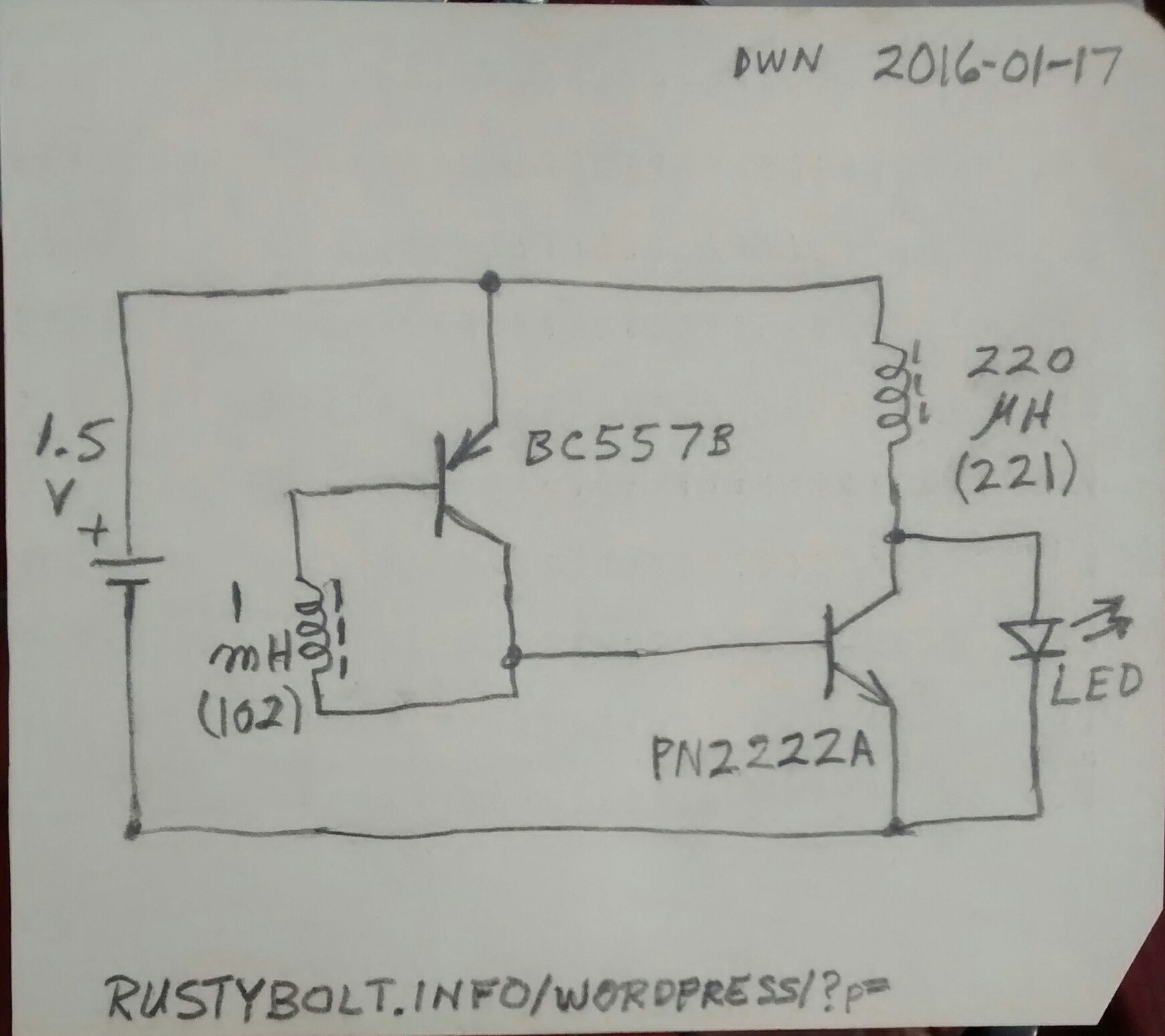
When I look at this, I see a Joule Thief with a single transistor, the PN2222A. The schematic says 2N2222A, but if it’s a plastic case, it is a PN2222A. The BC557B transistor, as shown, has the base connected to the collector with a very low resistance. The 1 mH inductor is typically from less than an ohm to a dozen or so ohms, depending on its construction, so to the BC557 it acts as a DC short. As shown in the original schematic, it is separate from the 220 uH inductor. The BC557B has the base and collector tied together, so it acts like a diode between the emitter and other two leads.
This means that as the battery voltage goes above 1 volt, this ‘diode’ and the base to emitter junction of the PN2222A start to conduct. The battery voltage goes up to 1.4 volts for a charged cell, and these two transistors conduct heavily, with an excessive amount of current. There is no resistance to limit the current, so the two transistors may overheat and be damaged. There should be a resistor between the BC557B and the base of the PN2222A to limit the current.
As shown, the two inductors are separate. But there would be no feedback and no oscillation if this were so. The two inductors must be close together and oriented correctly for it to oscillate and make light. If they are not, and the Joule Thief refuses to oscillate, then there is nothing to prevent the circuit from drawing excessive current, overheating, and further damage.
I would connect a few hundred ohm resistor in series with the BC557’s collector and the base of the PN2222A. It might help prevent excessive current. And the battery voltage should never, ever exceed 1.5 volts.
2016-01-18 TV Freeway Antenna
I saw this advertised on TV yesterday. I thought that with no power and connecting to the coax jack, this had to be an antenna. But it didn’t tell you that in the TV ad. So I went to their website and found that in the fine print, it says that it’s a VHF UHF antenna.
The flat ‘stick’ that makes up most of it probably has a piece of wire a few feet long imbedded inside of plastic. If the antenna is not outside and low to the ground, the reception will probably be poor. TV signals can be attenuated by the building walls. So you buy the ‘TV Freeway’ and find that it does not work well, so you send it back to get a refund. You lose your shipping fee, which is $8.00. The company then repackages your antenna and sells it to some other sucker. Who knows? They may have a limited amount of them that they may sell over and over again. By the way, I didn’t see anything where they tell you that you have to setup your TV for off the air broadcasts, and run the auto channel finder. For $23, instead it might be better to use a piece of wire in the TV jack.
2016-01-17 White LED Torch
I found this single cell white LED torch (flashlight) from EDN. The author claims it is efficient.
I like the Q5 active rectifier concept. It seems that designers are doing this more often, especially with high power designs. But they use MOSFETs, which do not draw gate current like a BJT draws base current. Since this is a low power design, every milliwatt not used is a milliwatt saved. So the Q5, Q4 and 3.3k resistor must waste some power, but is it less than a Schottky diode alone? I can’t guesstimate on this; I would have to measure both circuits.
That having been said, my theory has always been that adding a rectifier and filter capacitor is not necessary and is another point where power is lost. A single LED without any other components is the least lossy, in my opinion. However others have claimed that adding the rectifier and capacitor makes the led brighter, and I have confirmed that it’s a valid claim. I don’t know how this happens, though. To me it contradicts common sense.
In a conventional Joule Thief, the oscillator uses feedback from itself, so the frequency or pulse rate is determined by the oscillator itself. It runs at whatever frequency is optimum for the coil, mainly. But in this torch design, there is no feedback from the coil. The frequency (and waveform) is determined by the astable multivibrator Q1 and Q2. Therefore there is no way for the circuit to determine if the frequency is optimum for the coil. This may be okay in a product where the coil and frequency are optimized for the circuit. But for the experimenter, who may not have the exact parts, this could mean that the circuit may never get optimized. The 100k variable resistor may never adjust it to its brightest and highest efficiency.
I think the only way to find out is to temporarily disconnect one of the 1 nF capacitors and connect a pulse generator to the base. The range of frequencies can then be determined for the particular coil used. Or else connect the pulse generator to the left side of the 3.3k resistor to drive the high current transistor directly. The frequency and width of the pulse can then be controlled to get the best results for the coil, and then the parts values for the multivibrator can then be changed to duplicate the pulse generator.
Back to the circuit. The standard JT or the two transistor voltage boost circuit are simpler, and do an adequate job. I’ll have to ask the author or wait for someone to tell me why the design needed this astable multivibrator. The coil is not tuned, so given a coil of a certain inductance, the designer could have optimized the circuit for that coil and then eliminated the variable resistor.
More to follow, if I can get time from my other projects.
2015-12-29 Other Duracell Charger Failed
Last week I went to unplug the second Duracell charger, and one of the power plug blades pulled out and remained in the wall socket. A year or so ago I bought a package of two of these chargers and soon after the first one failed. I blogged it and filled out a report of it on the Consumer Product Safety Commission website.
This time, the bare metal plug was sticking out of the socket and it again posed a fire and safety hazard. I looked at the case around the missing blade and found that the case had three cracks radiating from the missing pin, one of which was between it and the remaining pin. Another crack was radiating out from the screw, at the top of the picture.
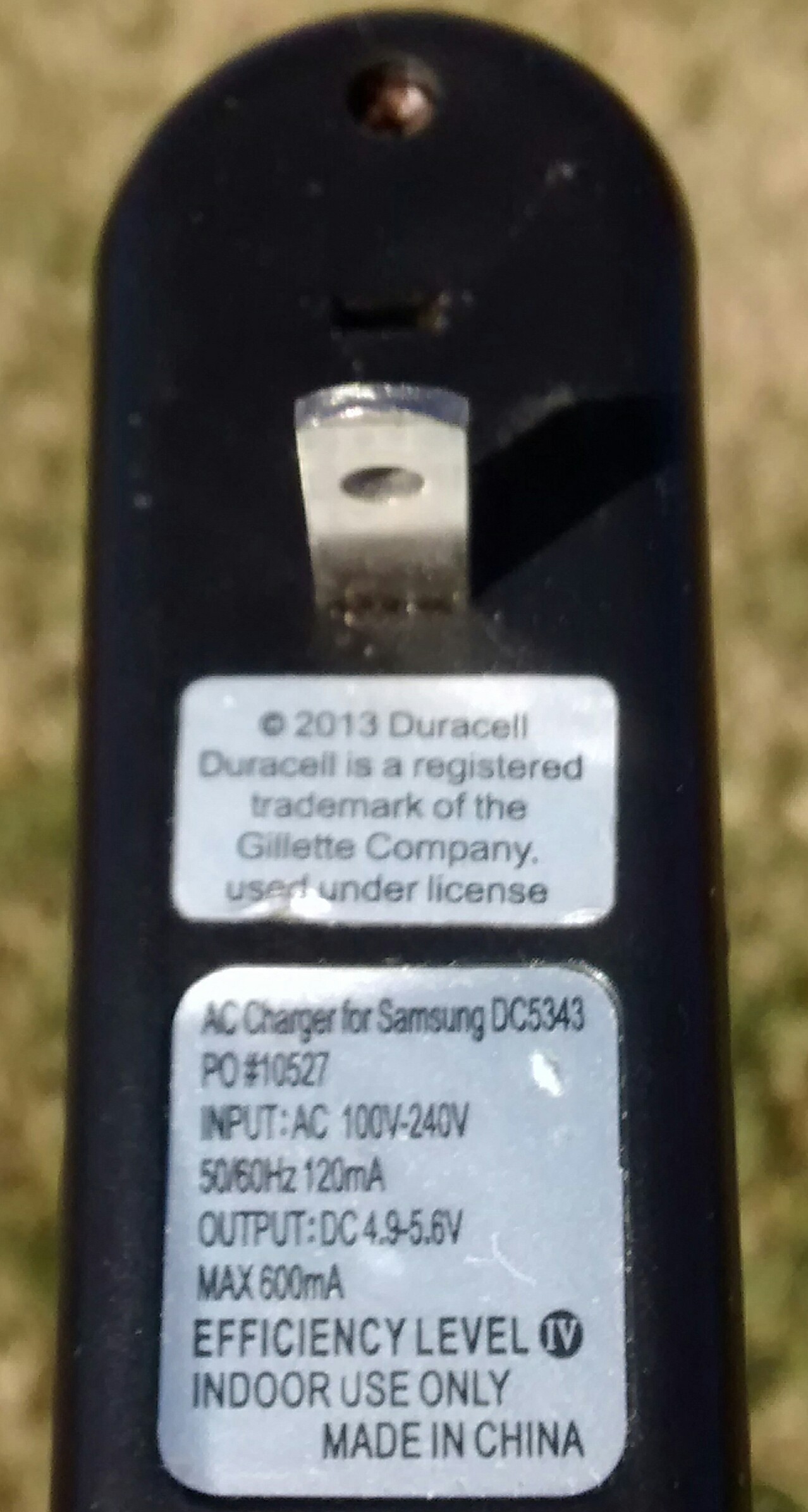
Two out of two of these Duracell chargers have now failed, for a 100% failure rate. I hope Gillete doesn’t make their shavers like this! Someone could be in for a shocking experience!
I don’t intend to follow up with another report because I checked later, and I don’t think anything was done with my original report. But this is important because everyone uses chargers nowadays.
