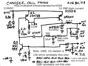
 I drew this schematic almost ten years ago, and of course the actual charger is nowhere to be found. I think it may have burned out somehow, and that was why I drew the schematic. Whatever the case, it does have current limiting, which has to be in anything like this that might be used by the consumer. The resistor in the note was so small that it was not possible to tell which way the bands were supposed to be read. I didn’t think of measuring it, however it might have been damaged. The 8550 is a very common transistor in consumer type electronics. It could be replaced by a BC327-25 but I don’t know if this substitute would give as much current. Maybe a better replacement would be a BD136.
Another thing I don’t remember anything about is the choke. It says 240 uH but I don’t remember if it was an axial or radial choke or toroid (probably not – they’re too expensive) or what the DC resistance was. I believe the whole circuit fit inside of a cigarette lighter plug, so the PC board had to be small, and so did the choke. There would also be a 1/4 amp fuse built into the plug.
Update 2014 Jan 2 – I was thinking about the resistor with 5 bands. This resistor along with the other resistors should divide the voltage so that when the output reaches 5V, the base voltage on the 2SC945 gets to .6V and starts limiting the output voltage. If the resistor was 130 ohms, it would be too low, and 100k ohms would be too high for this to happen, I believe. So the best solution that I can think of is to temporarily replace it with a 10k pot, and adjust it for the 5V output. Then remove the pot and replace it with a resistor of the same value. By the way, these chargers typically use a thin gauge wire in the cable, so it’s a good idea to have the output a few tenths of a volt above 5V, to compensate for the V drop in the wires.