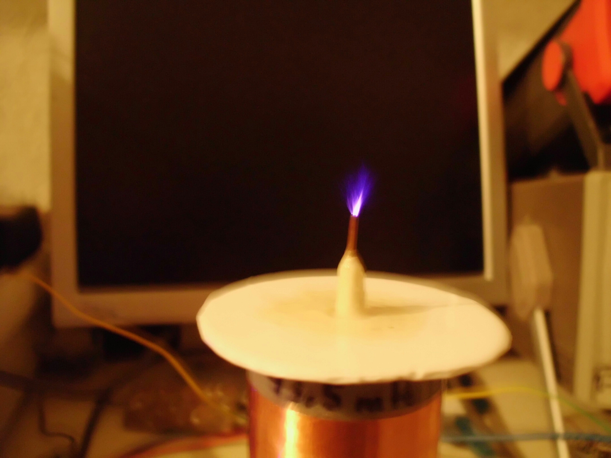
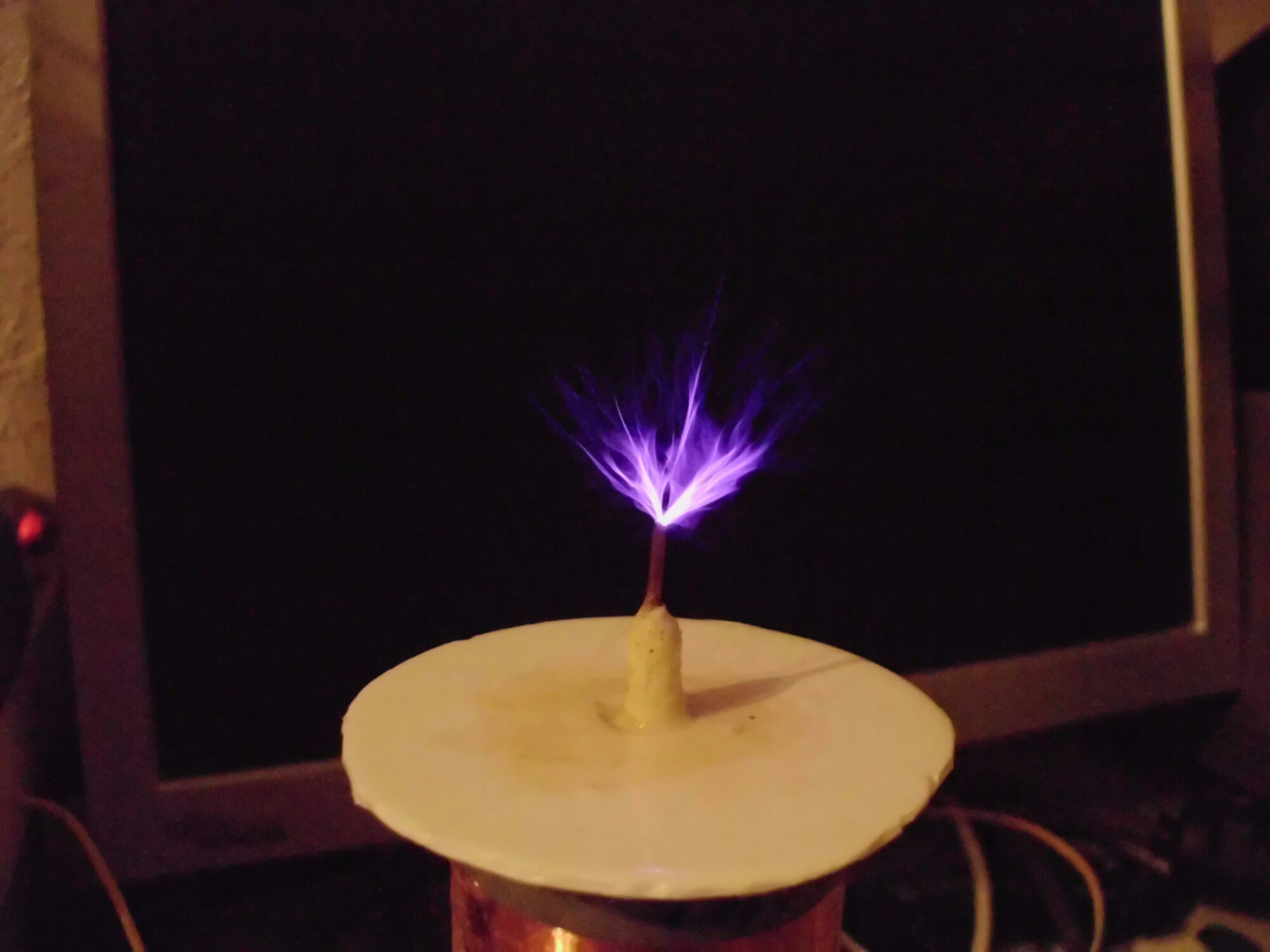
I received an email from Peter, who has planned on building a SSTC, solid state Tesla Coil. Peter gave me permission to post this email discussion to my blog. I have redacted some information for privacy reasons.
“From:”Peter Bergmann”
Date:Wed, Mar 23, 2016 at 5:31 PM
Subject:It´s alive!!
Dear Watson,
since I just can´t get the VN10KM mosfet I tried something else – Daniel
Eindhoven´s Audio Modulated Solid State Tesla Coil V 2.0 and it works!! I´m only using 70V DC at the moment and
I´m yet getting a decent breakout (it´s
designed for 325V DC).
See for yourself!!
L8r…”
I kind of like that smell of ozone that TCs give off when they’re arcing!
UPDTAE
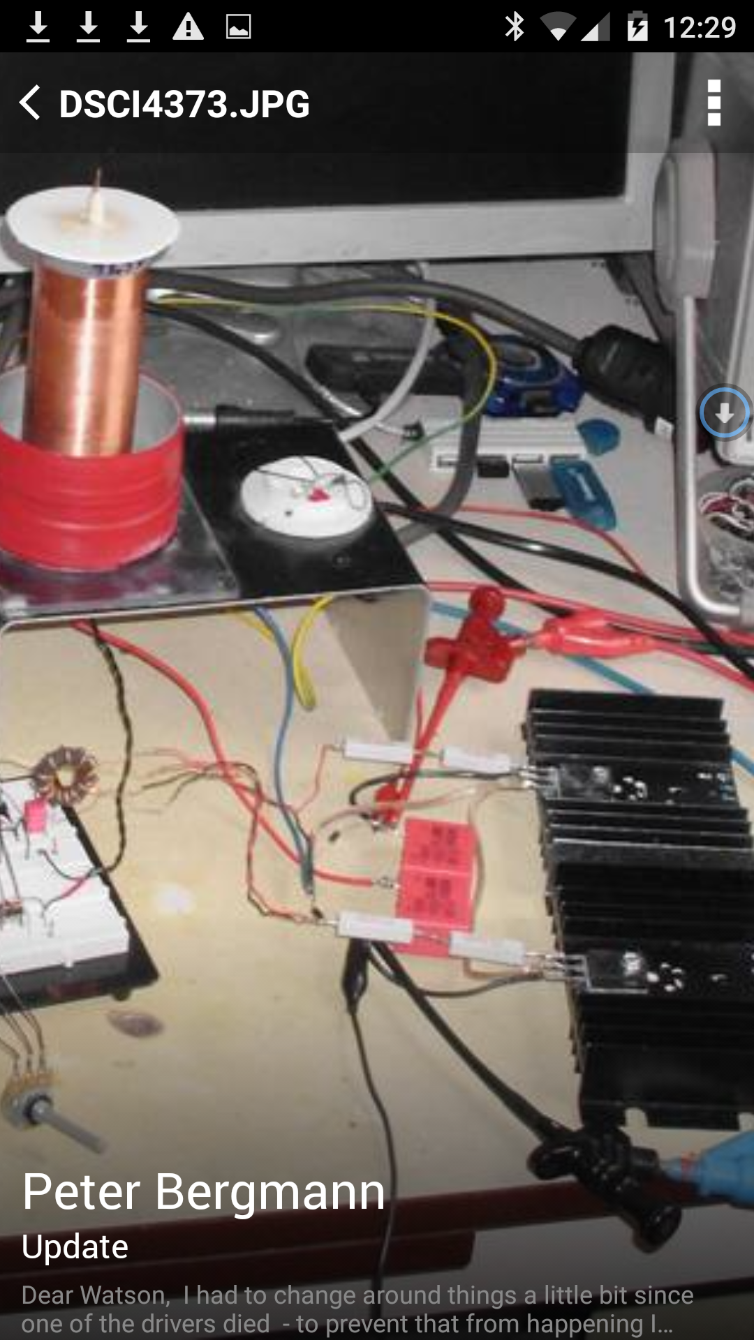
Update Mar 30 – I received more (not so good) photos from Peter, along with a video (can’t upload it yet) and a bit of text. I’ll continue after the photos.
Wow! I bet that made a nasty pop!
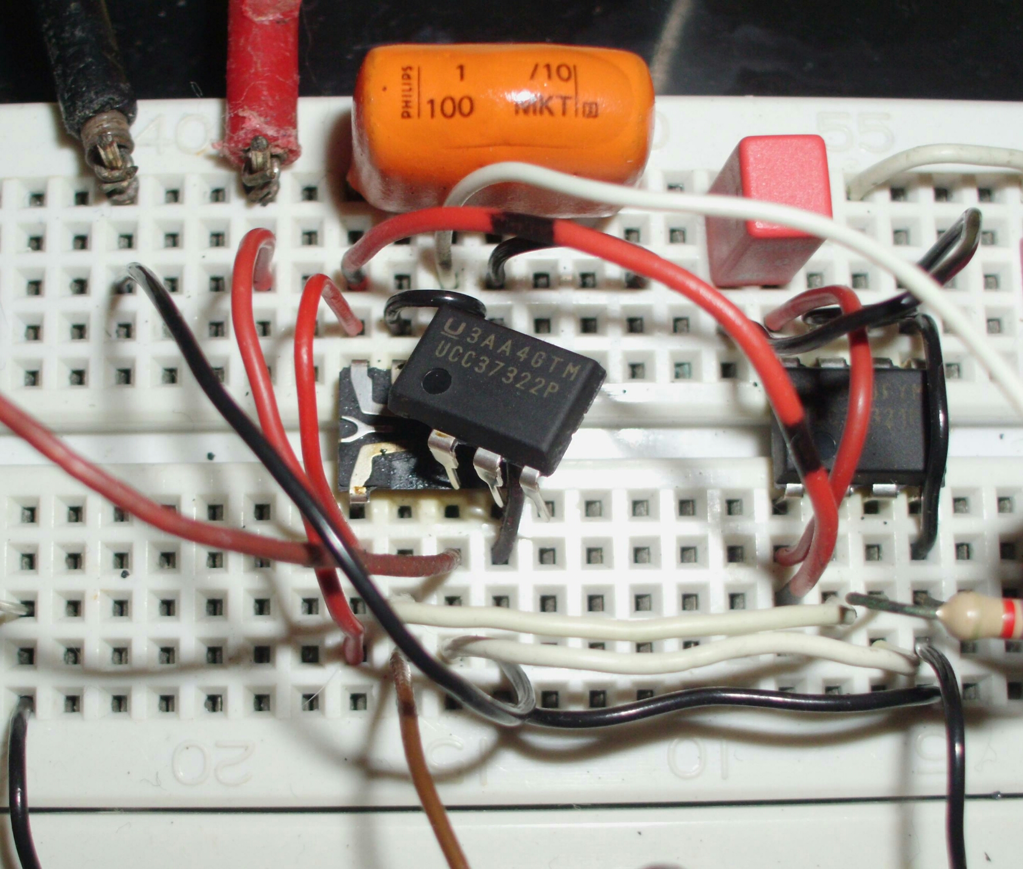
I enlarged his bench photo to show the power MOSFETs and driver transformer.
A big improvement over the first photo. I should point out that these arcs may damage electronic devices such as monitors and flash drives, so it’s best to keep them separated.
Okay, for some of my thoughts and guesstimates about what might have happened. The 2 MOSFETs require a minimum voltage on the gate to turn fully on. It’s best to have at least this much so that the MOSFETs spend as little time as possible between off and fully on. In this case, it’s possible to change the turns ratio on the driver transformer to change the gate voltage.
My guess as to what may have caused the driver failure. In the enlarged photo of the driver, I see two large wirewound resistors in series between the toroid and each gate. The wirewound resistors have a coil of wire which also has inductance. This L may be interacting with the C of the gates, making a series tuned LC circuit. These resistors should be noninductive, preferably carbon film, but not wirewound. If they get very warm, then the driver chip may be overloaded.
Due to the Miller Effect, some of the high voltage changes on the MOSFET drain goes through the capacitance and appears on the gate. This has to be overcome by the driver current. If the voltage fed back through the resistors to the driver chip exceeds the chip’s ratings, it can damage the chip. If the chip is rated to handle 12V supply voltage, I don’t think the reason it failed was because the supply voltage was too high. If the gates get enough drive voltage at a lower supply voltage, then why not use it, as long as the MOSFETs don’t get hot.
If you look at a 400 watt ATX switching supply, it has a small heatsink for the switching transistors, but it does have a fan to keep it cool. In fact, an old PC power supply would make a good SSTC because it has the on/off switch, line filter capacitors and inductors, bridge rectifier and electrolytic filter capacitors, and a fan and heat sink for the MOSFETs. Some boards have a TL494, which was used in Peter’s original schematic.
It might be a good idea to put a 15 volt, 1 watt zener in parallel with the driver output and common. The cathode has to go to positive, so that current flows through it only if the drive voltage exceeds the supply voltage, or if it goes negative. This is safety and protection for the driver chip – it’s not for performance.
Update Mar 31 – Peter sent a new photo of the MOSFETs with new resistors.
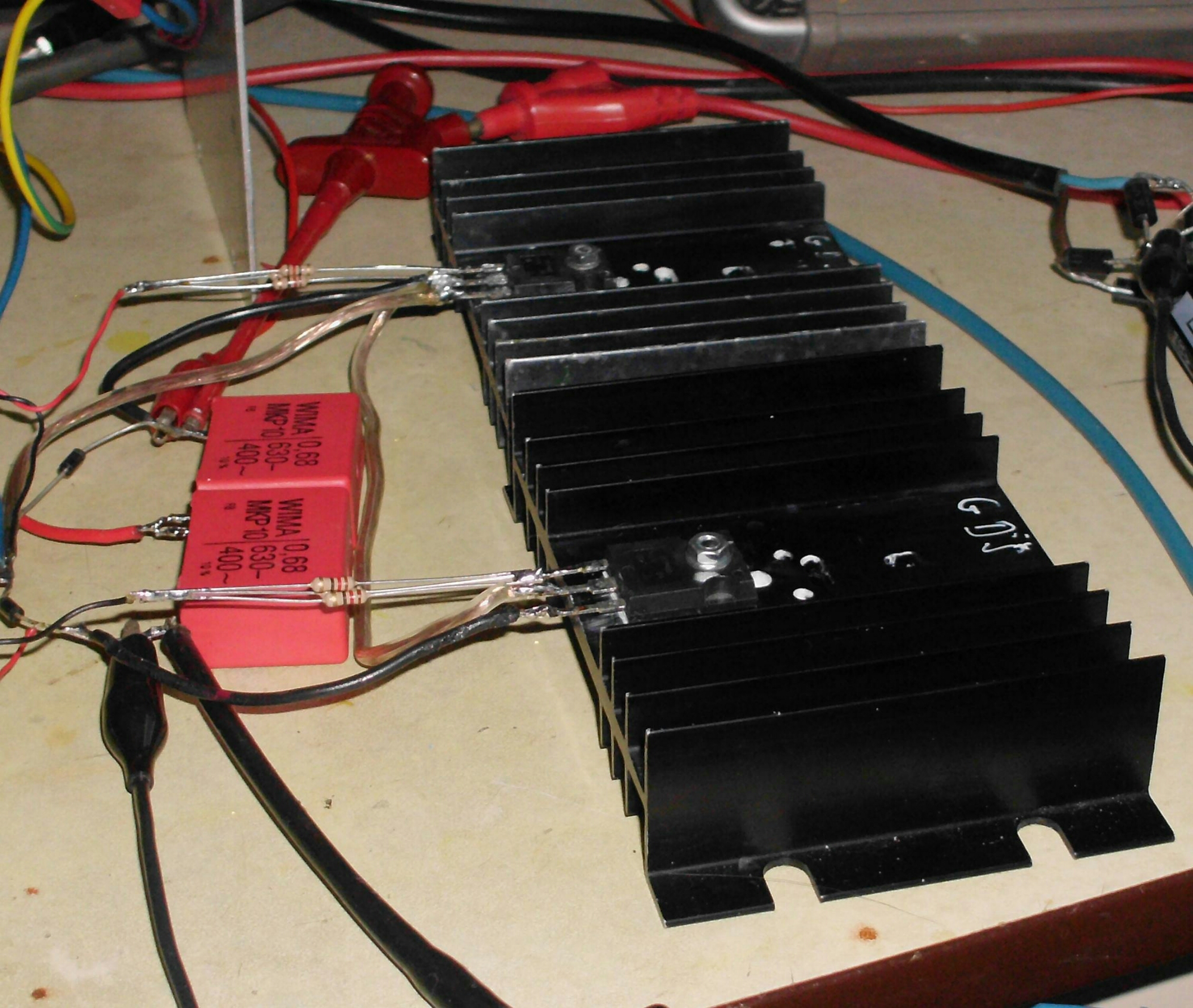
It looks to me to be three 12 ohm resistors in parallel, which gives 4 ohms to each gate. I think they should be better than wirewound resistors as long as they don’t overheat. This reminds me of something I should do. I should go to Harbor Freight, a discount tools importer, and buy an IR thermometer. With this, I can point it at a heat sink or resistor and get the temperature without touching the part, while it’s operating.
I built a DC-DC converter a few years ago that used a much lower power MOSFET. I used a 100 ohm resistor in series with the gate. I found that 100 ohms was too low, that it was best at a bit more, something like 120 ohms. I was surprised at how much difference that small change made. It was not difficult to find a 100 ohm trimmer pot. But Peter needs a trimpot with a very low value, only 10 to 20 ohms or so. I think I would use a 100 ohm trimpot in series with a 6.8 ohm resistor, replacing one of the 12 ohm resistors. Then it could be adjusted from less than 4 ohms up to about 6 ohms.
This is not a lot of adjustment, so some way has to be used to measure the coil’s performance. It’s convenient to measure the power supply current, even though it doesn’t tell me what the actual coil output is. But it’s very difficult to measure high voltage AC at radio frequencies. Another way is to put a CFL bulb near the coil, and measure the brightness of the bulb. The resistance of a CdS photocell in a dark room should give a valid relative CFL brightness. Instead, the CdS cell could be pointed at the arcs streaming out of the top of the coil.
Speaking of arcs, the small pill bottle exciter I made had a very feeble arc. So I went to Michaels arts and crafts store and bought some Styrofoam balls that are used for Christmas decorations. They were expensive for being almost nothing but air. I wrapped some bare copper wire around a 2 inch (50 mm) ball, then covered it with aluminum foil. I mounted this on top of the coil and it improved the arcs somewhat. The Styrofoam balls were also available in 4 inch (100mm) size.
If Peter’s MOSFETs are running cool, he may be able to put both of them on the same heat sink. Mounting the heat sink vertically will allow much more air to flow through the fins due to convection.
More fun in the next update.
Update 2016-05-03 – I received an email from Peter with a link to a short YouTube video of his SSTC in action. The arcs and sparks are impressive, much longer and thicker than earlier. But they are not as long as a TC with a sphere or ‘donut’ on the top. I think having one would help, but it’s up to Peter to experiment with one. The arcs and sparks are awesome the way it is.
