default

2017-01-22 FM Regenerative Receiver

I’ve been building another FM regenerative receiver. This one is supposed to use a BF244 JFET. But they were declared obsolete years ago, and aren’t available in quantities at a reasonable price. So I ordered some 2N3819 JFETs from Mouser and got them a few days ago. The 2N3819 is also a VHF JFET, so it should do the job.

I used this circuit. This is a superregenerative circuit – it self quenches at a supersonic frequency, as shown by the waveform.
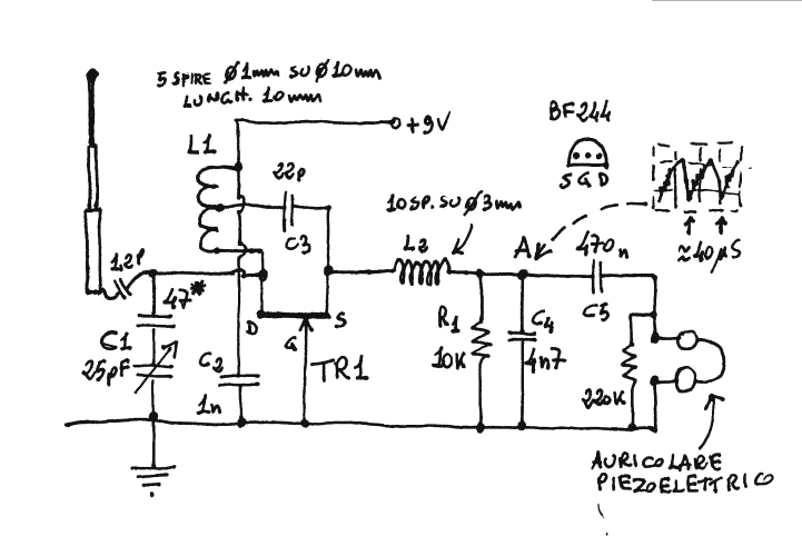
image Here’s the website where I obtained this.

The antenna is shown as a collapsible type from a portable radio, but I used a short piece of wire, abut 10 inches or 25 cm long. For the 1.2 pF antenna coupling capacitor I used a 0.2 to 5 pF miniature variable capacitor set to a low value. I will be using these a lot — I bought a bag of 500 of them for a few dollars.

I made L1 from 18 AWG wire, 5 turns wound on a Bic pen, about .36 in. diameter. It measured about 190 nanohenrys, but it’s less than that after I stretched it to lower its inductance. For C1 I used a 15 pF ceramic in parallel with one of the 0.2 to 5 pF mini variable capacitors (see changes below).

Added Audio Stage
I added a stage of audio amplification after the regen, in place of the ‘auriculare’ headphones that the schematic shows. It’s a SS9014D high gain audio transistor with the emitter grounded. The collector load resistor is 4.7k, and the base bias resistor between collector and base is 1 Megohm. It should be higher, probably 2.2 M. The DC blocking capacitors at both base and collector are 0.56 uF MLCCs. It’s loud enough to drive a 120 ohm earphone from a telephone handset.

Performance
After building a few of these, this is the first one that is sort of acting as a receiver. I got a little hiss and noise when I swept my dip meter’s frequency dial past this regenerative receivers frequency. I’m happy to find that it’s tuned to a frequency on the low end of the FM band. But I still haven’t heard any FM stations. It’s like these regen receivers are very insensitive. Some schematics I’ve seen have an RF preamplifier before the regen stage, but the impression that I got was this preamplifier was more for preventing the RF generated by the regen stage from going out from the antenna. I can hear this regen noise when I listen with a pocket FM radio, so it definitely radiates RF.

When I finished building it, I used a 10 inch wire for the antenna. I set the variable antenna coupling cap to a low value, probably about 1 pF. With the 10 inch wire, I get a 120 Hz buzz, which stops when I turn off my soldering iron. When I add a foot long alligator cliplead to the wire, the receiver goes silent, like it stopped oscillating. I need to find out why it’s sensitive to the antenna length.

It looks like I’m going to have to do some tweaking to get this receiver to work better.

I varied the supply voltage from 9 down to 4.5 volts, adjusting the tuning as I lowered it. I think it is a bit better when the supply is 6 volts DC. After adjusting the tuning, I could hear an FM station weakly mixed with the hum, noise and sputtering. This “first hear” is a defining moment, but whenever I move my hands, arms or body, the signal starts splattering loudly, so right now I have a proximity detector more than a radio receiver.

Next Day
Jan 24 morning I found that no matter what the supply voltage was, it still had problems with hum, noise, and dropping out. It’s supposed to quench at several tens of kHz, but I didn’t see that with a DMM or ‘scope. The original schematic had a pair of piezo earphones connected to the output. These are very high impedance and a minimal load. This audio preamplifier may be too low an impedance load. So I inserted a 10k resistor in series with the coupling capacitor C4. See here for an example (uses 22k res.)

I thought that part of the problem might be the L2 choke was not high enough value, only about half a microhenry. I removed it and wound more turns on a short length of soda straw. It measured 1.5 uH, three times the original. I put that in and it seemed to be less sensitive to my movements, and I heard a radio station a bit clearer. But as I tuned the 5 pF tuning capacitor, I found that the frequency was below the FM band, as low as 85 MHz. I removed the L1 coil and wound on a smaller diameter shaft of a drill bit about 0.3 inches diameter. I cut off some of the extra wire and reinstalled it in the circuit. Now the tuning is covering much more of the bottom on the FM band.

I tuned a pocket FM radio to a station at the bottom of the band, 88.5 MHz. I can now tune the regen receiver to that same station. But the regen receiver radiates RFI and causes the pocket radio’s audio to become quieter. The regen receiver’s audio is very weak, too. These two problems may mean that the regen receiver should have a RF preamplifier before the regen stage to prevent the interference from escaping and amplify the signal.

An My earlier regenerative receiver project.

I’ll continue this on the next blog tomorrow Jan 24.

default

2017-01-18 Simulating An Analog Meter

A detector or discriminator in an electronic device might need to be adjusted to a very few points on a scale of a hundred or more points.  A digital indicator typically indicates only a fraction of that, possibly 16 points.  This is why the analog meter is still useful: it can indicate a small change on a much larger scale.  I would like to make a device that is much cheaper than the analog meter, yet can indicate a small change in a much larger voltage or current.

I had a thought.  With today’s 3d technology and super strong magnets, it might be easy to do this.  Back in ‘the old days’ they used to make super sensitive meters by replacing the meter needle with a mirror.  Then a light went through a narrow slit and reflected off the mirror onto a somewhat distant surface, and movement that couldn’t be seen on the needle was easily seen on the light line on the surface. 

Another idea.  If the circuit is designed like a Wheatstone bridge, where the meter is showing only a small fraction of the total reading, then a 16 bar digital meter might be usable.  In other words, if the 16 bar meter shows 1/8 of the full scale reading, then it would be like looking at a part of the scale of a 128 bar meter.

But the problem is the measured quantity might suddenly change to a much different value which would no longer be in the small scale.  Therefore the small scale should be able to readjust itself to cover the new point.  There could be a ‘zero’ button to let the user recenter the 16 bar display on the changed value.

Some form of automatic feedback correction should be able to do this readjustment.  The adjustment could be done manually, but it seems that it can easily be done automatically.  The adjustment and settling times should be quick enough to not interfere with the user’s measurements.

One thing that occurred to me is that a good sensor of small level changes might be the ear. I could try connecting the voltage output to a voltage to frequency converter. The slight voltage changes would change the frequency and the ear could discriminate very small changes in the tone. A simple oscillator such as an astable multivibrator could be used.

Another idea. I’d like to investigate how sensitive the visual system is to flash rate. I found that the reason they use a starting pistol for races is that the mind processes sounds much faster than visual signals. That’s because there is much less brain used in processing sound, so there are less delays. But can a person do a visual comparison of the flash rates of a flashing LED? Or perhaps compare the flash rate of two LEDs?

Another possible solution, which seems to be very similar to the magic eye displays. The single LED would be mounted on a rotating disk. It could be mounted so the LED is seen on the edge of the disk. The disk spins and the led moves from Left to right. As the LED appears on the left, the circuit turns it on, and it remains on for the time determined by the voltage. Zero volts would have a very short time and the LED would turn off at the left side. Maximum voltage would turn off on the far right and other voltages would be in between. So the user would see something similar to a bar graph, with a varying length of light depending on the voltage. I realize that the mechanism might be complicated, but the rotating LED might be replaced with a stationary LED and a rotating mirror. Or the LED might be mounted on a lever that is driven by electromagnetics similar to a speaker’s voice coil. The whole idea here is to simplify and miniaturize the display.

default

2017-01-17 

From email sent by Peter, 2017-01-17

Good to hear from you, Peter.  I forgot about telling you that last year, I wasn’t able to read a message you sent me.  I don’t remember why. I apologize for not replying.

I wrote this up in a blog, but the blog isn’t accessible right now.  So I’m pasting a copy below.

The Linux I used for several years was Puppy Linux.  It’s a free download.  I just booted from a CD with the ISO image burned to it.  It worked okay, not much different than Windows.  I haven’t used Linux for the last few years, but I do stuff on my Android phone, and it has the same file structure.  So if you have that Android experience then you should find Linux similar.

I guess the main thing to determine is what you are going to do with the PC.  If you’re going to web browse and word processing and other office stuff (Office Libre is open source) then Linux will do okay.  If you have some special apps, like Scientific or tech apps, you may not be able to find one for Linux

My problem with Linux is that many programs or apps don’t have a Linux version.  Firefox, Chrome, and many open source apps were originally developed with Linux in mind.  The open source Wine is supposed to allow you to run Windows apps on Linux.  I downloaded it but never tried to run any Windows apps.  The laptop I was using was only 32 bit, but today’s PCs with 64 bit and more than 4G of memory should be able to do a decent job of running Wine.

There are other ways of running Linux.  You could run it in a virtual machine with VMware.  Or you could make your PC dual boot.  I haven’t done this, but there is plenty of information online and on YouTube to tell you how.  You can out Linux and all your stuff on a USB flash drive and boot up with this drive.

I’m very tempted to go back to Linux.  I have Win 8.1 on my desktop and Win 10 on a laptop, and I don’t use them enough to make it worth changing.  I mostly use my cellphone to do just about everything I need.  I have it right here, in my hand, so its very convenient.

default

2017-01-15 Tuned Circuit Tester

I’m building a tuned circuit tester, which is a Franklin Oscillator without the parallel tuned circuit.  I based it on the schematic I found at this URL.  The first amp is a JFET in common drain or source follower configuration, which then drives the 2nd stage, a PNP transistor in common base configuration, so there is no signal inversion and the common base has voltage gain.  Some signal is used to drive the third emitter follower stage, and its output is used to drive a frequency counter. 

The following photo shows the changes I made.  Most are increased capacitor values, such as coupling and bypass, which don’t affect the circuit very much.

I used an MPF102 JFET for the first amp, and a 2SC3355 for the emitter follower.  Instead of a 1N4148 I used a 1SS98 UHF diode for the JFET’s gate.

After completing the basic circuit, I double checked it and found a bias resistor that needed to be soldered.  It pays to double-check!  I then soldered a coil of 6 turns of 20AWG bare copper wire in parallel with a 24 pF trimmer capacitor across the ‘unknown tuned circuit’ pins.  I applied 9 volts and checked with a dip meter and FM radio, and tuned the circuit to the bottom of the FM band.  It oscillates just fine – I got a strong signal.  I tried adjusting the trimpot, but it doesn’t do a lot, just changes the power.

I changed the tuned circuit to a 2.6 uH toroid coil in parallel with a 100 pF disk capacitor.  This should resonate at 9.7 MHz.  I put a short wire through the toroid and made a  single turn loop by soldering the ends together.  This allows me to put the coil of the dip meter inside of the loop to pickup the signal.  I powered it up, but I got nothing.  I thought it may be because the loop is acting as a shorted turn and stops the oscillator.

I removed the single turn loop from the toroid. I thought, what would be a good way to indicate that the circuit is oscillating? I decided that a half wave doubler and LED should be fine. I added two 1N914 diodes, a filter capacitor and red LED to the output. I checked the LED to make sure it would light up. When I powered it up, the circuit did not seem to be oscillating and the LED did not light. I decided to go back to the 6 turns and trimmer capacitor. I powered it up and adjusted the trimmer so I could hear the dead carrier in my radio. I got a strong carrier, but the LED still didn’t light up. My thoughts are the circuit is oscillating but the amplitude is not high enough to make the half wave doubler rectify and light the LED. Maybe I need an amplifier after the diodes? …

Things are turned around. Circuits typically oscillate easier at low frequencies, and harder at high frequencies, but not in this case. Weird.

default

2000-01-01 watsonspics.blogspot.com

This is a link to my pictures I posted.

watsonspics

Pictures, for the most part, of schematics I’ve drawn, using ExpressPCB, free software. There is little or no text. A few may have been drawn by others. Those from Quantsuff (quantsuff.com) have a QS in the name. I’ve received permission from QS to use them. Solid State Systems is a name I used many years ago.

I can no longer access these pictures.  The evil blogger.com deleted my watsonseblog.blogspot.com account.

default

2009-01-10 Experimental Joule Thief

Date 2017-01-12
Link to
Experimental Joule Thief

default

2017-01-10 Work Light

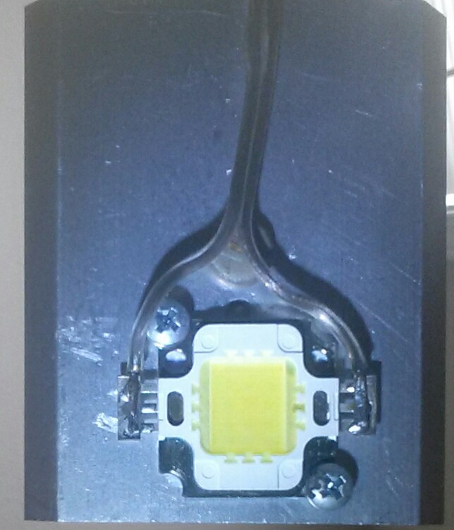
Here’s a shot of one of my very bright work lights.  It’s a 10 watt multi chip LED mounted on a heat sink, which gets a bit warm.  I mounted the heat sink on a piece of 6 AWG bare copper wire which lets me reposition the light a bit.

It’s a daylight color temperature, but I have some of the same LEDs that are warm white.  I powered it with a 12 volt wall wart and a switchmode DC – DC converter.  I can adjust the current and brightness.

image

default

2017-01-04 ASCII Chart

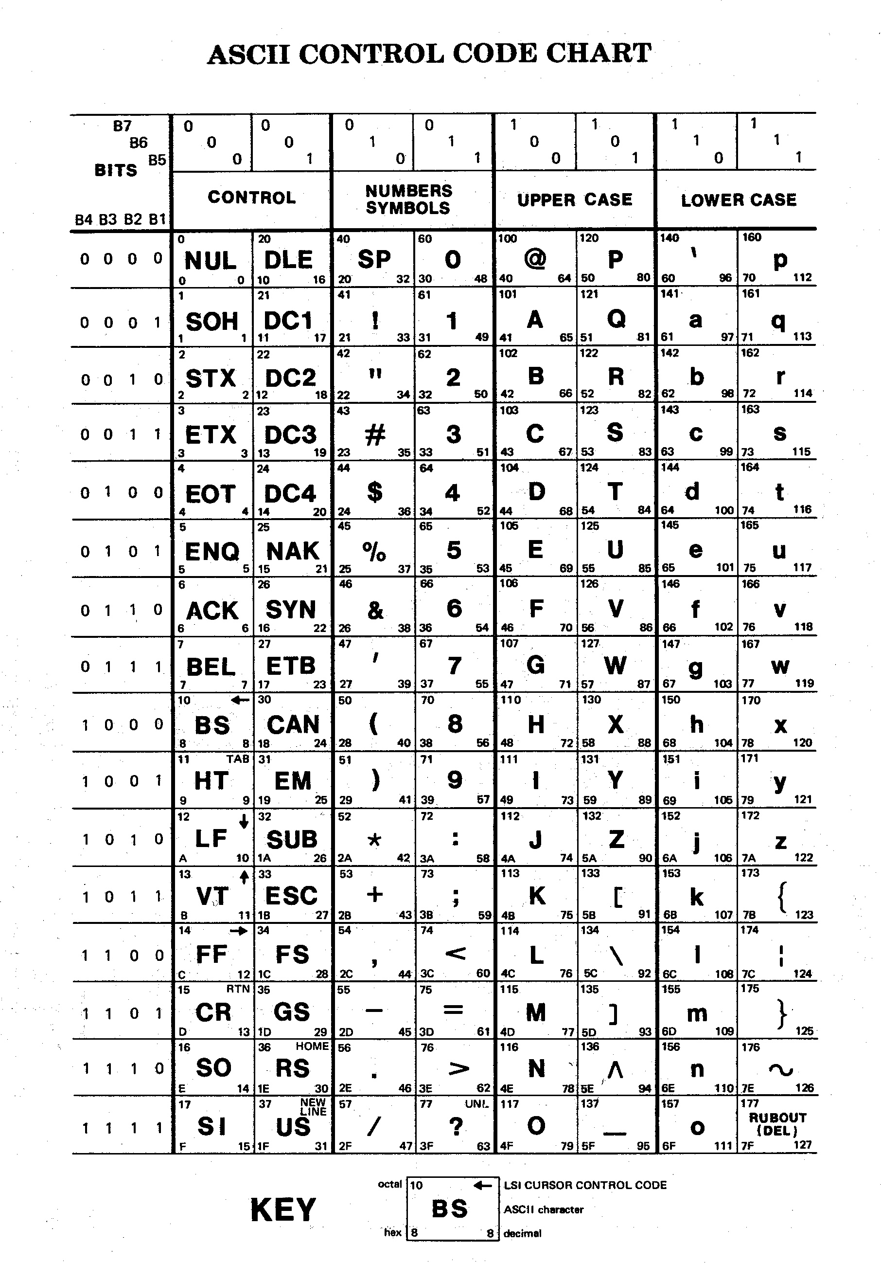
I tried posting this on Facebutt, but it thinks this single image .GIF is a movie!  So I’m putting it where all can get it.

default

2016-12-25 Merry Christmas

Jingle Bell,

It’s cold as hell,

45 degrees today;

default

2016-12-10 Snowden – Courage And Fear

Someone I know posted this to Facebook:

“Courage is not living without fear. Courage is being scared to death and doing the right thing anyway.”

What does this have to do with Snowden?  Well, think about it.  Did he weigh the consequences of his actions?  Did he think about what would happen if he went ahead with his revelations?  I’m sure he realized that there would be negative consequences for his actions.  When he made the choice, I’m certain he knew that there would be repercussions and his choice would have a negative impact on him.  But as he made the discoveries that would send him down this path, did he know that the evidence he had uncovered would be worth risking his life and future?

I’m sure he didn’t make a sudden snap decision.  He must’ve spent some time looking at data he had access to, and developed a sense over time that the information was so important that he had to do what he did.  I’m very curious because it was a life changing decision that he made.

© RustyBolt.Info/wordpress
CyberChimps