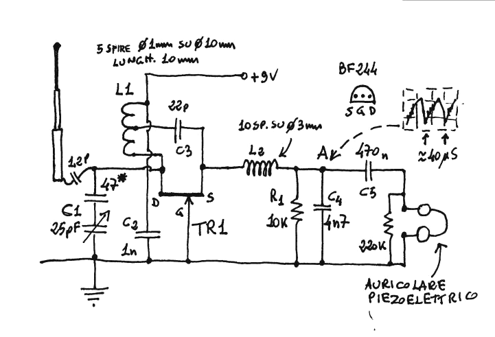
I’ve been building another FM regenerative receiver. This one is supposed to use a BF244 JFET. But they were declared obsolete years ago, and aren’t available in quantities at a reasonable price. So I ordered some 2N3819 JFETs from Mouser and got them a few days ago. The 2N3819 is also a VHF JFET, so it should do the job.
I used this circuit. This is a superregenerative circuit – it self quenches at a supersonic frequency, as shown by the waveform.
 Here’s the website where I obtained this.
The antenna is shown as a collapsible type from a portable radio, but I used a short piece of wire, abut 10 inches or 25 cm long. For the 1.2 pF antenna coupling capacitor I used a 0.2 to 5 pF miniature variable capacitor set to a low value. I will be using these a lot — I bought a bag of 500 of them for a few dollars.
I made L1 from 18 AWG wire, 5 turns wound on a Bic pen, about .36 in. diameter. It measured about 190 nanohenrys, but it’s less than that after I stretched it to lower its inductance. For C1 I used a 15 pF ceramic in parallel with one of the 0.2 to 5 pF mini variable capacitors (see changes below).
Added Audio Stage
I added a stage of audio amplification after the regen, in place of the ‘auriculare’ headphones that the schematic shows. It’s a SS9014D high gain audio transistor with the emitter grounded. The collector load resistor is 4.7k, and the base bias resistor between collector and base is 1 Megohm. It should be higher, probably 2.2 M. The DC blocking capacitors at both base and collector are 0.56 uF MLCCs. It’s loud enough to drive a 120 ohm earphone from a telephone handset.
Performance
After building a few of these, this is the first one that is sort of acting as a receiver. I got a little hiss and noise when I swept my dip meter’s frequency dial past this regenerative receivers frequency. I’m happy to find that it’s tuned to a frequency on the low end of the FM band. But I still haven’t heard any FM stations. It’s like these regen receivers are very insensitive. Some schematics I’ve seen have an RF preamplifier before the regen stage, but the impression that I got was this preamplifier was more for preventing the RF generated by the regen stage from going out from the antenna. I can hear this regen noise when I listen with a pocket FM radio, so it definitely radiates RF.
When I finished building it, I used a 10 inch wire for the antenna. I set the variable antenna coupling cap to a low value, probably about 1 pF. With the 10 inch wire, I get a 120 Hz buzz, which stops when I turn off my soldering iron. When I add a foot long alligator cliplead to the wire, the receiver goes silent, like it stopped oscillating. I need to find out why it’s sensitive to the antenna length.
It looks like I’m going to have to do some tweaking to get this receiver to work better.
I varied the supply voltage from 9 down to 4.5 volts, adjusting the tuning as I lowered it. I think it is a bit better when the supply is 6 volts DC. After adjusting the tuning, I could hear an FM station weakly mixed with the hum, noise and sputtering. This “first hear” is a defining moment, but whenever I move my hands, arms or body, the signal starts splattering loudly, so right now I have a proximity detector more than a radio receiver.
Next Day
Jan 24 morning I found that no matter what the supply voltage was, it still had problems with hum, noise, and dropping out. It’s supposed to quench at several tens of kHz, but I didn’t see that with a DMM or ‘scope. The original schematic had a pair of piezo earphones connected to the output. These are very high impedance and a minimal load. This audio preamplifier may be too low an impedance load. So I inserted a 10k resistor in series with the coupling capacitor C4. See here for an example (uses 22k res.)
I thought that part of the problem might be the L2 choke was not high enough value, only about half a microhenry. I removed it and wound more turns on a short length of soda straw. It measured 1.5 uH, three times the original. I put that in and it seemed to be less sensitive to my movements, and I heard a radio station a bit clearer. But as I tuned the 5 pF tuning capacitor, I found that the frequency was below the FM band, as low as 85 MHz. I removed the L1 coil and wound on a smaller diameter shaft of a drill bit about 0.3 inches diameter. I cut off some of the extra wire and reinstalled it in the circuit. Now the tuning is covering much more of the bottom on the FM band.
I tuned a pocket FM radio to a station at the bottom of the band, 88.5 MHz. I can now tune the regen receiver to that same station. But the regen receiver radiates RFI and causes the pocket radio’s audio to become quieter. The regen receiver’s audio is very weak, too. These two problems may mean that the regen receiver should have a RF preamplifier before the regen stage to prevent the interference from escaping and amplify the signal.
An My earlier regenerative receiver project.
I’ll continue this on the next blog tomorrow Jan 24.
A todos nos pasa lo mismo y en el mismo orden