default

2017-05-05 Field Strength Meter Schematic Error

From my post to FB groups

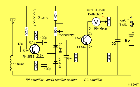
​Well, here’s another circuit that’s doubtful that it works.  It looks to me that the 22n capacitor bypasses the amplified RF to ground so the diodes can’t rectify any RF.  If there was a 1 to 10k resistor between the diodes and 22n capacitor, then I could be persuaded that the diodes would detect the RF.

http://www.talkingelectronics.com/projects/FieldStrengthMeterMkl/images/FieldStrengthMeterMkICct.gif

I’ve received a lot of comments, so the reader should check them on FB.

default

2017-05-04 Interrupting The Supply V to the Oscillator

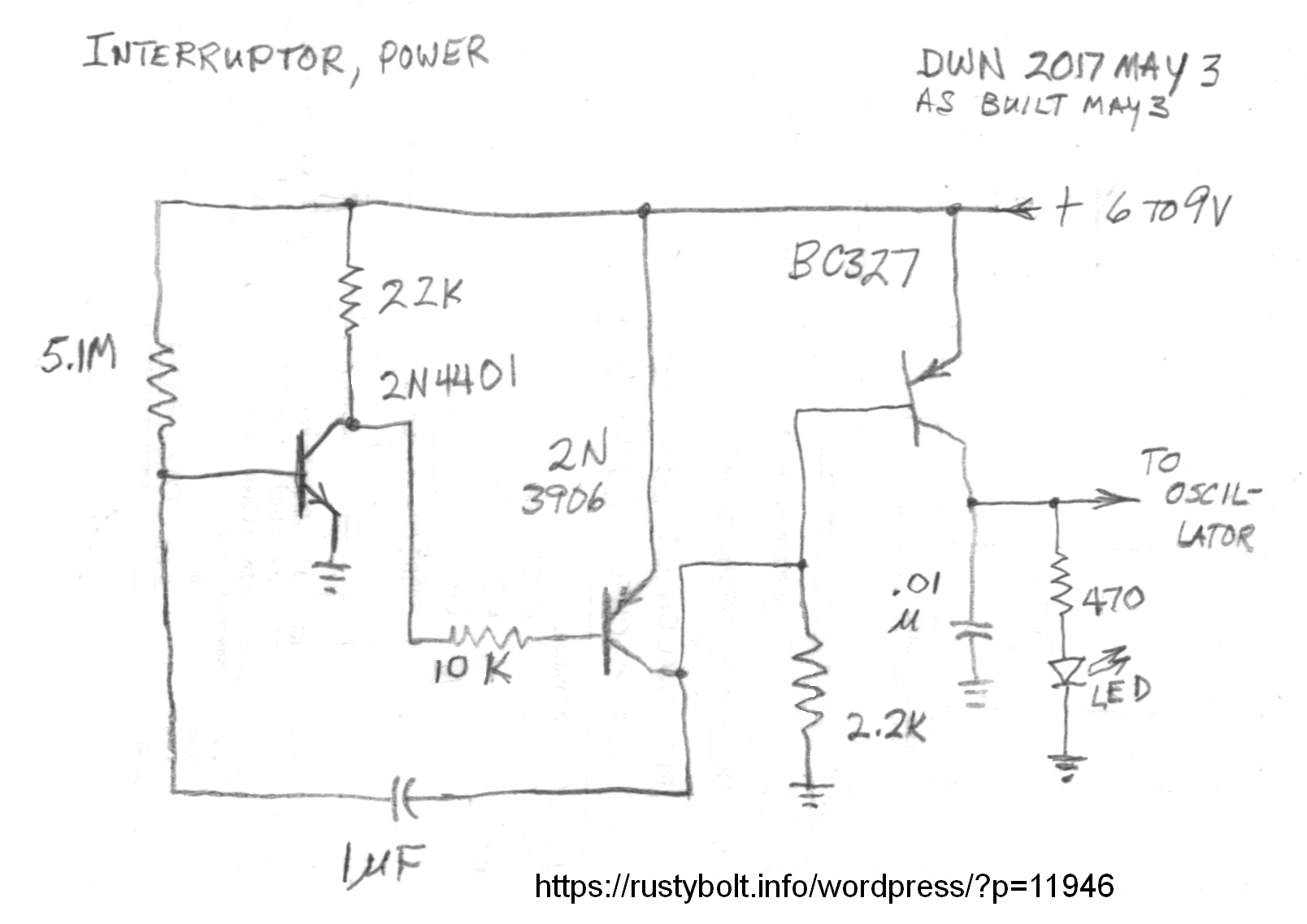
I was working on the 27 MHz oscillator for testing the regens, and I thought it would be a good idea to turn the carrier off for a small fraction of a second every 1 or so seconds.  So I built a two transistor flasher with a third transistor to invert the pulses.  Instead of mostly off with an on pulse every second, the output is mostly on with a very short off interruption every second.

I built the circuit and I put a LED on the output and found that it was always off unless I touched the base of the first transistor.  I found that the two transistors had too much gain, so I added the 22k resistor as a collector load resistor for the first transistor.  The circuit started working properly.  The interruption rate is 1.4 per second.

I got the Suntech AM-FM-SW Radio for $20.  It’s so cheap and the performance is seriously lacking.  The FM band has images that seem as strong as the stations, so I put the extendable antenna down, and the performance wasn’t as bad.  But then I can’t hear the difference between the quiet spots on the dial and the unmodulated carrier of my oscillator.   So now I have my oscillator powered by the interruptor circuit, and the short interruptions make it easy to tell the difference between the carrier and other signals.

default

2017-05-03 Cheap Frequency Counter

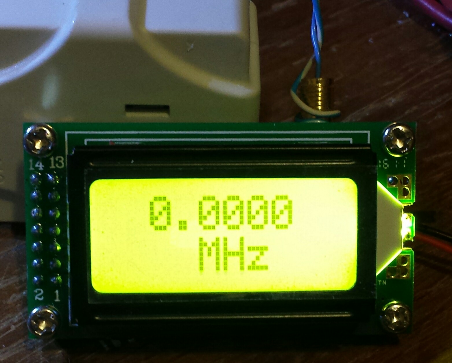
I got these today in the mail.  Notice the temporary wire I poked into the connector.  I ordered some adapters but I haven’t received them yet.  I bought a frequency counter with the rubber ducky antenna but it doesn’t have the sensitivity that this cheap one has.  I got two of these for $28, free shipping.

These have made it a lot easier to adjust the oscillators to the right frequency.  I no longer have to tune the receiver to the carrier to find its frequency.  I just hold the wire close to the oscillator and I get the frequency to within a hundred Hz.  I no longer have to find the oscillator’s carrier among other strong carriers, hoping I got the right one.

When I received the package, each counter was sealed in a plastic package.  But the corner of the package was cut off, and the battery connector had been pulled out.  This leads me to believe that the counters were opened up to test and/or calibrate them to indicate the correct frequency.  I had read that some consumers had received these and they indicated the wrong frequency.  Apparently the makers retested them to find any problems.

I also bought a Gooit frequency counter.  This wasn’t very much, about fifteen dollars from an eBay seller.  This is also sensitive enough to pick up a small low power transmitter.  It has a short pull up antenna but no input jack.  

default

2017-04-27 Superregen FM BCB Receiver

I built this superregenerative FM broadcast band receiver today.  This circuit is similar to the one I posted on January 22.
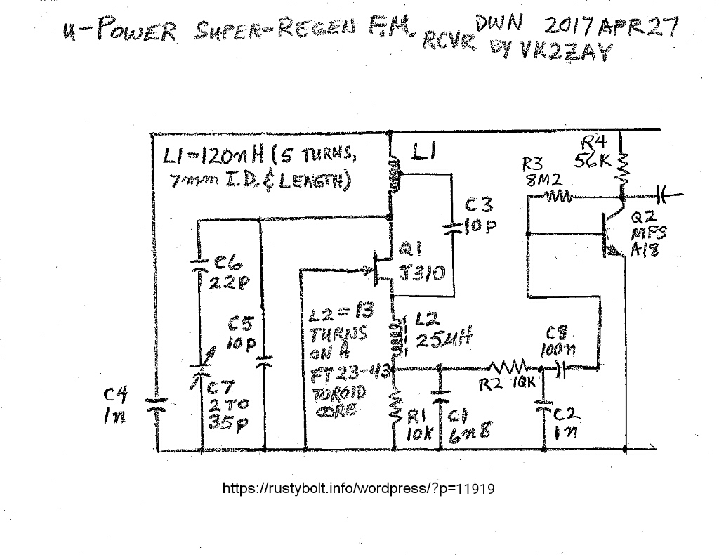
Here is a list of parts values I used:

ANT – 12 cm insulated wire connected through 10 pF capacitor to FET source.

C4 – two 2.2 nF MLCCs from + to ground plane ( I built this on a small piece of copper circuit board.)

C5 – 18 pF silver mica capacitor 

C6 – not used – replaced with a jumper.

C7 (A and B) – two 0.2 to 5 pF plastic variable capacitors 

C3 – 10 pF silver mica capacitor

R1 – 10k 5% carbon film resistor (May 7 I changed this to 3.3k, then 2.2k.)

R3 – 2.7 M 5% carbon film resistor 

R4 – 22k 5% carbon film resistor, later reduced to 11k to help make earphone louder. 

Q1 – 2N3819 VHF JFET, later BF256 and BF244.

Q2 – C9018 high gain low noise NPN BJT similar to MPSA18.

L1 – 6 turns 20 AWG bare copper wire wound on drill bit shank, appx 6mm ID.  Coil stretched so it measured appx 120 nH.

L2 – 6 turns 24 AWG solid insulated wire on a FT37-43 toroid core, measured 14 uH, later rewound to 33 uH, cut back to 25 uH.

(Some of following copied from FB post)

My Superregen won’t quench.  I built the circuit found here, with a few changes.

http://www.vk2zay.net/article/129

I used a 2N3819 for Q1, and a FT37-43 for L2, measuring 14 uH.  At the end in his notes he gave some limits to the values of some parts, and the values I used seem to be within the limits.

For an antenna I connected a short 12 cm length of wire to the FET’s source, as he recommended.  The coil is 6 turns of 20 AWG bare copper wire, wound on a drill bit shank, and spread out untl it measured about 120 nanohenrys.  I used an 18 pF silver mica capacitor and two 0.2 to 5 pF variable capacitors in parallel with the coil.

 I used a dip meter to tune the coil and capacitors to a point within the FM broadcast band.  I measure a little over 2 volts at the source, so the JFET is conducting in the linear region.

I used a scope to check the R1 – C1 point and I see no oscillations.  I’m using 9VDC regulated for the supply.  I connected the Q2 output to an amplifier and I get noise like a hiss but no stations.  I can hear my cell phone burps loudly, and hum if I touch points in the circuit.  So I’m fairly confident that I have the circuit set up properly  – no major malfunctions.

I just thought of one thing I can do.  I can put the circuit on a variable supply and try various supply voltages.  I’ll try that and update this.

Update evening until 1:30 AM – I experimented with several different parts.  I put it on a variable supply and it seemed to do a little bit better at 6 volts.  At the beginning of this session I could receive only a single FM station, one that’s very close and powerful.  This was with the 12 cm wire connected through a 10 pF capacitor to the source.  I couldn’t hear any other stations.

I removed the L2 and rewound it, so it has 9 turns on the FT37-43 core and measured 33 uH.  The audio seemed to be louder.  But as I tune, the audio is garbled, seems that the level is too high for the audio amplifier I’m using.  Still only one station.  

I moved ‘center tap’ one turn closer to the positive end of the tank coil.  I also spread the turns a bit, and adjusted the variable capacitors a lot.  I think the coil could be longer and lower inductance so it will cover the high end of the FM band.

I searched online for more information about this regen design.  I found another builder’s story of the problems he had with his regen.  He used too much bypassing capacitance, so he reduced it and the regen started to quench.  So I also reduced mine.  I changed C4A and B to a single 1 nF capacitor as shown in the original schematic.  But it still doesn’t work.

Update Evening Apr 28 – I was looking at a tiny .jpg I had saved of the pinouts for the 2N3819, and I noticed they were backwards.  Instead of S  G  D, the pic showed D  G  S.  So I checked three datasheets to see.  The ON Semi showed S  G  D, the Temic showed S  G  D, and the Central Semi showed D  G  S (!!!)   So what brand of JFET was in my circuit?  Oh, no!  It was Central Semi!  So I removed the 2N3819 and flipped it over, and soldered ot back in.  Now I tuned for the strong station but I couldn’t hear anything on the earphone.  The one thing I was certan of was that there was uncertainty on what the true pinout was for the 2N3819 that I was using, so I decided to use another JFET.  I chose a BF244, which I have plenty of, and it’s rated for VHF or better.  After I installed the BF244, I still couldn’t hear the strong station.  I was looking for a possible short, and I looked inside of the coil and found a blob of solder shorting turns.  Once I got that out, the strong station tuned in, but I heard no change, just a single strong station.  The voltage at the source was about the same as before, a bit over 2 volts.

So I got rid of a questionable JFET, but the replacement didn’t perform any better.  I can hypothesize that the second JFET in this circuit with no change implies the poor performance problem is most likely not being caused by the JFET itself.

There’s an old saying that says “Amplifiers will oscillate, oscillators won’t.”  Well this oscillator sure doesn’t want to oscillate, it just won’t quench.

Update May 2 – I spent a lot of time this evening trying to get a sound out of the circuit, but it was dead silent.  I cut out the JFET and relaced it with a BF256B, and it started picking up a very weak signal.  Apparently the JFET had died when I was unsoldering or soldering the various parts.

Update May 7 evening – I had been working on the 27 MHz Vackar ‘signal generator’ for a few days, among other things.  Now I’m back to try and get this FM regen to quench or to squegg as some others have called it.  One thing I had not experimted with was the JFET current.  This is limited by R1, which has been 10k.  The JFET’s current is less than a half milliamp, so I decided to reduce the resistor to get about a milliamp.  I removed the 10k and replaced it with a 3.3k.  Wow, this made a big difference!  All of a sudden the earphone started hissing like a superregen is supposed to when it’s not tuned to a station.  I checked the signal at the top of this 3.3k with the scope and it was quenching at about 88 kHz.  The DC voltage was 2.4 volts, so the source current is still under 1 mA, about 0.74 mA. 

I can tune it and hear only one strong station, but I hear quieting in the hiss at some other points, so it’s trying to pick up some not so strong stations.

The quenching starts at just under 9 volts supply voltage.  If I drop below that, the quench and hiss stops.  I think the circuit would work better if I reduced the 3.3k to let more current through the JFET.

I put a 6.8k in parallel with the 3.3k, so it’s equal to 2.22 k.  I heard the strong signal, but it was garbled.  I turned up the supply voltage, and as I passed 11 volts and got to 12V the audio cleared up.   It sounded much better.   The voltage across the resistors was 2.5 volts DC, so the JFET current was a little more than 1 mA.  And I’m happy to say that this is the first superregen receiver that I’ve been able to hear a station clearly.  And after many hours of tinkering I can say I’ve accomplished something.

default

2017-04-23 Linear Power Supply Renovation 

In the past I’ve built several of these small power supplies to use around the house, and they come in handy.  But those others used a 12 VAC transformer instead of an AC adapter, so I had to add a fuse and other stuff to prevent shock.  Using the AC adapter is much more convenient because all of that is included in the wall wart.  All I have to deal with is low voltage DC.  Those power supplies used old designs that didn’t have good regulation.  I wanted to replace them with a linear regulator chip which gives excellent performance.
Years ago I had built a 9 VDC shunt regulated power supply, low current, only 40 mA max.  A shunt regulator wastes the power that isn’t being used by the load, in this case it was built for powering a pocket transistor radio.  A Zener diode is a good example of a shunt regulator.  If none of the Zener’s current is used, then the current is wasted heating the Zener diode.  So I dissembled the shunt regulator and used some of its parts to build a new regulator using a LM317.  I also scrapped another power supply for the circuit board and some parts.  Both of these used an old transformer type wall wart with outputs about 13 volts no load.  So I used the adapter rated 9VDC at 600 mA.

I’ve been building these small RF circuits and I’ve been using a bunch of bench supplies to power them.  The circuits need very little power, but the voltage needs to be stable, so that’s why I decided to build a few of these with  adjustable regulator chips.  A few other parts and I’ll have a 1.25 to 9 VDC well regulated supply, that can put out about 200 mA to a load, up to 8 volts.  The wall wart output drops as the current goes above 150 mA and the regulated output drops below 9 volts.  If I had a better AC adapter that wouldn’t happen.  But I can live with the lower current.

This new power supply uses a LM317 with a 270 ohm resistor from Output to Adjust pins, and a 2.5 k wirewound pot from the Adjust pin to negative.  This would allow me to adjust the voltage up to 12V, but the adapter can’t put out that much under load, so I put a resistor in parallel with the pot to limit the voltage to 9 volts maximum.  But even at 9 volts, if I put a load of more than 150 mA on it, the voltage drops below 9 volts.

I added some capacitors and diodes to the basic design to filter ripple, and help protect the circuit from overvoltage or reverse voltage.  This is pretty much standard practice with the adjustable VRs.

I used several EMI / RFI suppressor sleeves on the input and output wires to prevent the RF from the circuits from radiating from the supply.  I added a 2200 uF, 16VDC capacitor on the circuit board to help the capacitor in the wall wart.  

The circuit fit on a perfboard the size of a large postage stamp.  I got the heatsink from an old PC power supply, but I should mount the heatsink on the aluminum lid of a project box for better heat sinking.

default

2017-04-21 Signal Generator for 27 MHz

I need a source of signals on various frequencies to test how well my bandpass filters are aligned.  I built a Vackar Oscillator with tuning over a few CB channels, mainly 27.095 to 27.255 MHz.  These are radio control frequencies.  Like a Colpitts oscillator, the Vackar’s resonant circuit has two capacitors in series with the center point grounded.  The difference is that Vackar has the transistor’s parasitic capacitance somewhat isolated from the resonant circuit.

I’ve been dealing with building a stable RF inductor and trying to get it to be stable with changes in temperature.  Last night I put a coil on it wound with 26 AWG solid enameled copper wire, wound on and secured to a 1 inch length of bamboo skewer stick, and it measured 0.8 uH.  I tuned my Kenwood R-1000 receiver to it.  By this morning it had drifted 6 kHz.

I’m taking advice and adding capacitance to the resonant tank and reducing the inductance.  I changed the coil to 9 turns 20 AWG solid enameled wire on a T50-2 iron powder toroid core, measured at 0.72 uH.  In order to bring the frequency down, I added a variable capacitor, 8 to 50 pF, N750 tempco, in series with a 47 pF silver mica to the ‘cold’ (left) side of the resonant tank.

Update Apr 24 – several days ago I ordered some powdered iron cores, T37-7, which are supposed to have very low temperature coefficient.  I got them today, so I wound one with 23 AWG solid plastic insulated wire from a Cat5e datacomm cable.  I started with 11 turns, but I removed some until the inductance measured 0.62 uH.  The dip meter showed the signal was above 30 MHz, so I added another 100 pF in parallel with the 100 pF C1, and changed the 47 pF to 68 pF.  When I adjusted the 8 to 50 pF, I got the carrier on the receiver.  I tweaked the 0.2 to 5 pF, and got it to be on 27.145 MHz.  I also added a 33 ohm resistor between the collector and C5.

I left it alone while I was doing something else, and came back later and found that it was still at about the same frequency.  I have noticed that while I’m working on the circuit the radiant heat from the soldering iron and even from my body made the circuit drift.  But with the latest modifications the long term drift has decreased, and I can go away for hours and the circuit is still at about the same frequency.  Short term drift isn’t as good, the frequency goes up and down dozens of kHz over the period of a minute.  The toroid core moves around when I pick up the circuit, and the frequency warbles as the coil moves, but I can fix that by gluing the core down.

While I was poking around I noticed that I could make the RF modulate with hum when I touched the point where the two R6 resistors, 10k and 22k joined.  So I connected a PSO to this point to modulate the RF with about 1kHz.  But when I tune the receiver across the band, I notice that I hear the tone at several places over about 10 kHz.  This points me to believe that the modulation is more FM than it is AM.

Update Apr 25 – I have been increasing the capacitance of the resonant tank.  I got to the point where the variable capacitors would not tune high enough, so I removed one turn from the core.  Then the frequency was too high so I had to add more capacitance.  According to what I’ve read the Vackar oscillator should have a 6 to 1 ratio of the divider capacitors, so I changed them to 10 and 47 pF which is 4.7 to 1 ratio, better but still not quite 6.

While I was juggling the capacitor values I used one that was 220 pF Y5P.  This worked but the frequency drifted a huge amount, varying tens of kHz in a few minutes.  So I replaced it with a silver mica capacitor, and the drifting came back down to a point that was much more stable.  The temperature coefficient of these capacitors is very important for good stability – the lowest is best.

Along the way I disconnected everything to the right of C5 and R7.  It just wasn’t effective at adjusting the frequency.

The toroid core is still a T37-7 with 10 turns, and it’s about 550 nanohenrys.  I determined the total capacitance using 27 MHz and 550 nH, and it came to 73 picofarads.  That’s better than approx. 44 pF I started out at.  The Xc = Xl = 80 ohms, which is well below the 100 ohms maximum recommended by others.

Update 2017-05-05 – I have begun another blog with further updates.

default

2017-04-20 27.145 MHz Transmitter And Receiver Pt 1

I’m trying to make a simple wireless alarm link.  The transmitter will be in an unheated garage, so the only way to easily get it to stay within the -+ 10kHz channel will be to use a XO (crystal oscillator).  

But for the receiver, I figured the best way to go would be to put a bandpass filter right after the antenna to keep the high power CB stations from wiping out my signal.  I figured a Pi type bandpass filter coupled by a low PF capacitor between the two LC sections.  Or perhaps I should use a link coupling so I can move the link away from the resonant winding to get the passband to be narrow.  This is what I need to experiment with.

After that a LO and mixer to downconvert the signal.  The reason I built the tunable Vackar Oscillator is for tweaking the bandpass filter.  I don’t have a decent RF signal gen for this freq.  I have an old tube signal generator, a Realistic 22-040 clunker from the old days when they still called them Megacycles.  And I have a Heathkit Dipmeter, which I find very useful.

I have some old aluminum IF cans from tube radios that I can use to hold the filter and jacks, and connect stuff together with some RG-174 coax.  I need to make the bandpass filter narrow band.  I thought about using some crystals to get a narrow bandwidth.  I had a low profile crystal for 27 MHz, and I checked it with my crystal checker, and it checked intermittently then died.  I think the crystal element was damaged by too much power.  It has to be small to fit in the small package, and it most likely was broken by the power from the crystal checker.

I have looked at several downconverter designs and I liked one because it used a crystal that was half the frequency.  The converter used two 1N4148 diodes in anti-parallel, so it rectified both halves of the sine wave, thus doubling the frequency.  I also got some SA602 chips for downconverting RF.  There are several designs using this chip when I do a search.

default

2017-04-20 Buying SMTs From Newark Element14

I think I’m set for life when I need SMT transistors – I bought hundreds of them from Newark Element14.  They are having a discount sale; some of these transistors are discounted to less than 2 cents apiece whether you buy 1 or a thousand.  Some are as low as a penny – $0.011.  The discounted ones have a red circled star next to the price.  So I bought a hundred or so of the most used transistors.  They have many other parts discounted, too, and shipping can be free, depending on the carrier.

Note:  I checked the datasheets.  Some of them were mislabeled, in other words the datasheet was for a SOT-23 package but the transistor is in a different package, even smaller than SOT-23.  So check to make sure you are getting the ones you can use.

What I bought.  I edited out some private info.

58K9429 MMBTH81 Tape and Reel Cut 1 100
$0.027 $
Customer Part Number: Customer PO Line Number: 001
Description: BIPOLAR TRANSISTOR, PNP, -20V SOT-23-3; Transistor Polarity:PNP; Collector Emitter Voltage V(br)ceo:20V; Transition Frequency ft:600MHz; Power Dissipation Pd:225mW; DC Collector Current:50mA; DC Current Gain hFE:60hFE
Shipping Via: UPS


Expected Ship Date: 04/19/2017      Expected Ship Quantity: 100      Final Expected Ship Date: 04/19/2017     
Line No:2 Stock No: 
Manufacturer Part No: 
UOM:
Quantity: Price: 
Extended Price: 
67P3530 KST10MTF Tape and Reel Cut 1 25
$0.021 $
Customer Part Number: Customer PO Line Number: 002
Description: RF TRANSISTOR, NPN 25V 650MHZ TO-92; Transistor Polarity:NPN; Collector Emitter Voltage V(br)ceo:25V; Transition Frequency ft:650MHz; Power Dissipation Pd:350mW; DC Collector Current:-; DC Current Gain hFE:60hFE; No. of Pins:3Pins
Shipping Via: UPS


Expected Ship Date: 04/19/2017      Expected Ship Quantity: 25      Final Expected Ship Date: 04/19/2017     
Line No:3 Stock No: 
Manufacturer Part No: 
UOM:
Quantity: Price: 
Extended Price: 
45J0609 BC858CLT1G Tape and Reel Cut 1 200
$0.011 $
Customer Part Number: Customer PO Line Number: 003
Description: BIPOLAR TRANSISTOR, PNP -30V SOT-23; Transistor Polarity:PNP; Collector Emitter Voltage V(br)ceo:-30V; Transition Frequency ft:100MHz; Power Dissipation Pd:225mW; DC Collector Current:-100mA; DC Current Gain hFE:420hFE
Shipping Via: UPS


Expected Ship Date: 04/19/2017      Expected Ship Quantity: 200      Final Expected Ship Date: 04/19/2017     
Line No:4 Stock No: 
Manufacturer Part No: 
UOM:
Quantity: Price: 
Extended Price: 
88H4790 MMBT4401LT1G Tape and Reel Cut 1 250
$0.013 $
Customer Part Number: Customer PO Line Number: 004
Description: BIPOLAR TRANSISTOR, NPN, 40V; Transistor Polarity:NPN; Collector Emitter Voltage V(br)ceo:40V; Transition Frequency ft:250MHz; Power Dissipation Pd:300mW; DC Collector Current:600mA; DC Current Gain hFE:250hFE; No. of Pins:3Pins
Shipping Via: UPS


Expected Ship Date: 04/19/2017      Expected Ship Quantity: 250      Final Expected Ship Date: 04/19/2017     
Line No:5 Stock No: 
Manufacturer Part No: 
UOM:
Quantity: Price: 
Extended Price: 
10N9479 MMBT2222ATT1G Tape and Reel Cut 1 300
$0.019 $
Customer Part Number: Customer PO Line Number: 005
Description: BIPOLAR TRANSISTOR, NPN, 40V; Transistor Polarity:NPN; Collector Emitter Voltage V(br)ceo:40V; Transition Frequency ft:300MHz; Power Dissipation Pd:150mW; DC Collector Current:600mA; DC Current Gain hFE:100hFE; No. of Pins:3Pins
Shipping Via: UPS


Expected Ship Date: 04/19/2017      Expected Ship Quantity: 300      Final Expected Ship Date: 04/19/2017     
Line No:6 Stock No: 
Manufacturer Part No: 
UOM:
Quantity: Price: 
Extended Price: 
09R9378 BC847CDW1T1G Tape and Reel Cut 1 200
$0.024 $
Customer Part Number: Customer PO Line Number: 006
Description: BIPOLAR TRANSISTOR, NPN, DUAL, 45V, SOT363; Transistor Polarity:Dual NPN; Collector Emitter Voltage V(br)ceo:45V; Transition Frequency ft:100MHz; Power Dissipation Pd:380mW; DC Collector Current:100mA; DC Current Gain hFE:270hFE
Shipping Via: UPS


Expected Ship Date: 04/19/2017      Expected Ship Quantity: 200      Final Expected Ship Date: 04/19/2017     
Line No:7 Stock No: 
Manufacturer Part No: 
UOM:
Quantity: Price: 
Extended Price: 
75R0777 MMBT3904,215 Tape and Reel Cut 1 300
$0.013 $
Customer Part Number: Customer PO Line Number: 007
Description: SWITCHING TRANSISTOR, NPN, 40V, 200MA, 3-SOT-23; Transistor Polarity:NPN; Collector Emitter Voltage V(br)ceo:40V; Transition Frequency ft:300MHz; Power Dissipation Pd:250mW; DC Collector Current:200mA; DC Current Gain hFE:100hFE
Shipping Via: UPS


Expected Ship Date: 04/19/2017     Expected Ship Quantity: 300    Final Expected Ship Date: 04/19/2017     
Line No:8 Stock No: 
Manufacturer Part No: 
UOM:
Quantity: Price: 
Extended Price: 
67P3546 PN2222ATFR Tape and Reel Cut 1 200
$0.028 $
Customer Part Number: Customer PO Line Number: 008
Description: TRANSISTOR, NPN, 40V, TO-92; Transistor Polarity:NPN; Collector Emitter Voltage V(br)ceo:40V; Transition Frequency ft:300MHz; Power Dissipation Pd:625mW; DC Collector Current:1A; DC Current Gain hFE:35hFE; No. of Pins:3Pins
Shipping Via: UPS


Expected Ship Date: 04/19/2017  Expected Ship Quantity: 200   Final Expected Ship Date: 04/19/2017     
Line No:9 Stock No: 
Manufacturer Part No: 
UOM:
Quantity: Price: 
Extended Price: 
98H0755 MMBT5089LT1G Tape and Reel Cut 1 100
$0.026 $
Customer Part Number: Customer PO Line Number: 009
Description: BJT, NPN, 25V,SOT-23; Transistor Polarity:NPN; Collector Emitter Voltage V(br)ceo:25V; Transition Frequency ft:50MHz; Power Dissipation Pd:225mW; DC Collector Current:50mA; DC Current Gain hFE:1200hFE; No. of Pins:3Pins
Shipping Via: UPS


Expected Ship Date: 04/19/2017   Expected Ship Quantity: 100   Final Expected Ship Date: 04/19/2017     
Line No:10 Stock No: 
Manufacturer Part No: 
UOM:
Quantity: Price: 
Extended Price: 
75R0736 BC847C,215 Tape and Reel Cut 1 200 $0.016 $
Customer Part Number: Customer PO Line Number: 010
Description: BIPOLAR TRANSISTOR, NPN, 45V, 100MA, 3-SOT-23; Transistor Polarity:NPN; Collector Emitter Voltage V(br)ceo:45V; Transition Frequency ft:100MHz; Power Dissipation Pd:250mW; DC Collector Current:100mA; DC Current Gain hFE:420hFE
Shipping Via: UPS


Expected Ship Date: 04/19/2017      Expected Ship Quantity: 200      Final Expected Ship Date: 04/19/2017     
Line No:11 Stock No: 
Manufacturer Part No: 
UOM:
Quantity: Price: 
Extended Price: 
79R5028 PBSS303ND,115 Tape and Reel Cut 1 25
$0.059 $
Customer Part Number: Customer PO Line Number: 011
Description: BISS TRANSISTOR, NPN, 60V, 3A, 6-SOT-457; Transistor Polarity:NPN; Collector Emitter Voltage V(br)ceo:60V; Transition Frequency ft:140MHz; Power Dissipation Pd:1.1W; DC Collector Current:3A; DC Current Gain hFE:570hFE
Shipping Via: UPS


Expected Ship Date: 04/19/2017      Expected Ship Quantity: 25      Final Expected Ship Date: 04/19/2017     
Line No:12 Stock No: 
Manufacturer Part No: 
UOM:
Quantity: Price: 
Extended Price: 
09R9448 MMBT2907ALT3G Tape and Reel Cut 1 200
$0.013 $
Customer Part Number: Customer PO Line Number: 012
Description: BIPOLAR TRANSISTOR, PNP, -60V, SOT-23; Transistor Polarity:PNP; Collector Emitter Voltage V(br)ceo:60V; Transition Frequency ft:200MHz; Power Dissipation Pd:225mW; DC Collector Current:-600mA; DC Current Gain hFE:100hFE
default

2017-04-17 Lost Blogs

I had problems with the blog and I had to reinstall the app.  All of the local copies got deleted from Jan 21 up until today.  I haven’t been able to do any blogging or moderate comments since Jan 21.

default

2017-04-18 The Exploded Transistor 

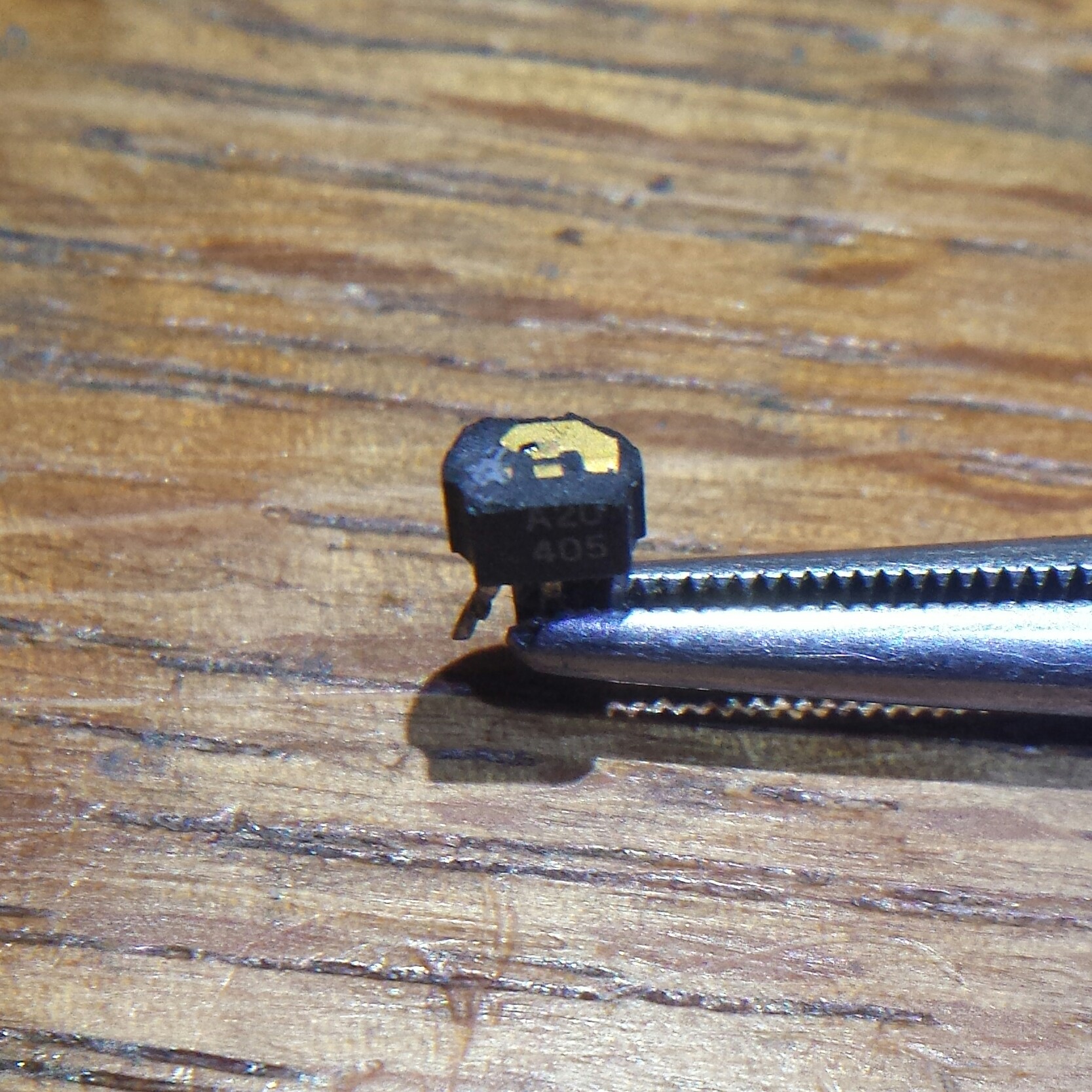
Someone said that you’re not a tech until you blow up a chip so violently that it imbeds itself into the ceiling.  Well, this transistor seems to have exploded violently.  It was inside a CFL bulb and when it went off, it probably wasn’t even heard.  It handled over a hundred volts, and it was just not up to the job.

© RustyBolt.Info/wordpress
CyberChimps