default

2017-09-14 Menu Display And Single Button Selection

I will post this to Facebook Arduino group.

I’ve been thinking about how the cheap clock kit I built uses a single button to step through and set the hours, minutes and seconds.  It’s a bit tedious and it took me a bit of practice to get the hang of it.  But it makes possible stepping through a menu of things and selecting an item.  What I thought would be a good Arduino project would be to use this method to remotely set or control IoT’s from a menu of selections.

I realize that a lot of IoT fans would say, just use your smartphone to do it.  Put the menu on screen and push the buttons next to them.  You’re right.  It’s probably the best way to do it.  But what if we don’t have a smartphone, or it’s broken, or it’s not secure enough?  Or let’s say I just want this to be an alternative project.

Which brings up another problem.  How do I display the menu?  I thought that a 27″(680mm) TV monitor would be a good way to display the menu so it could be read from a distance of 3 to 5 yards/meters.  One display is not that expensive, and I could use an old 4:3 flat panel display.  The problem is how to get the menu out of the Arduino and onto the display.  Some way to convert the text to a VGA video signal.

But then I thought that I could save $$$ by using an existing TV to display the menu.  What I could do is generate a low resolution screen, say 32 characters wide by 8 lines high.  This could be read from across the room on a large screen TV.  But how do I get it into the TV?

I could generate a composite video signal and plug it into the plugs in the back of the TV.  But I have to switch the video source to see the menu.

I think it would be easier to generate an RF signal and the TV could be switched to Channel 3 or 4, like the old video games like Atari did.  But can a modern digital TV even display an old fashioned analog signal?  I think some TVs just say this format can’t be displayed or similar error messages.

I also thought about using an old B/W low resolution display of a few inches/cm across.  Then project the screen onto the wall with a lens, so it can be read from across the room.

I’m looking for other similar ideas, and more brainstorming.  The basic plan I want to stick to includes a single button for control, and a selection menu, with submenues if needed, to display.  And the display should be viewable from a distance.

default

2017-09-11 Cassette Tape Stuck In Player

From post in FB group Vintage transistor radios

I need some advice.  I bought a Sony combo cassette player and AM/FM radio ‘boombox’ back years ago when it was new.  A few years later I put a cassette in it and played a recording of my now deceased parents.  I was listening when it started slurring, and I saw the two reels going in opposite directions.  I hit the stop button but too late.  The tape had stuck to the capstan and wound up on it, pulling the tape off the reels.

The cassette holder is the ‘slot’ that’s hinged at the bottom and pops open at the top to accept the cassette.  It completely surrounds the cassette.  After the foulup, I tried to open it up. But because the tape is wound around the capstan, it’s too big to pull out of the cassette.  So the cassette is preventing the holder from opening, it just barely opens.

I haven’t attempted to force the holder open because I consider the recording precious and would rather sacrifice anything else to save the cassette tape.  It has remained that way for at least a decade.

I was thinking that I could take a dremel tool and cut open the door, and save the cassette.  I thought I should ask here to see if anyone else has had this happen and if they have found a solution.  Thanks.

From Jim Gabriel

I would see if you could get to the bottom of the mechanism, turn the capstan fly wheel and see if you can somehow turn the supply wheel and wind it that way. To get the tape back in the cassette.
from Phillip Grace

I would open up the deck and try to manually spin the capstan flywheel backwards in order to loosen the tape. I’ve done this sort of thing in the past to retrieve tapes jammed in players.
Sony is famous for bad belts and idler wheels!  If you can get to the flywheel/capstan assy, rotate it to release the tape then carefully wind tape back up.

From Richard S W

Sony is famous for bad belts and idler wheels!  If you can get to the flywheel/capstan assy, rotate it to release the tape then carefully wind tape back up.
I understand the concern, but it may loosen up what’s in the capstan shaft enough to get the tape out.  You might loose 3 secs of tape but you will salvage the rest.

default

2017-09-10 How Long Can An Arduino Circuit Last?

My answer to a FB Arduino group question on Sept 17

Dan Rogers has the right idea.  The protoboard, with all the holes in it, was never meant to be permanent.  The contacts in each hole lose their springiness as they are used to hold wires.  The contacts can become intermittent after awhile.  As time goes on, the contacts corrode, and the corrosion makes the contacts intermittent or high resistance, and the circuit may have strange problems.  Things that draw higher current, such as relays, can work unreliably or not at all.  The corrosion causes noise in sensitive circuits.

The worst thing that can happen to a protoboard circuit is vibration.  If you have one in a robot or vehicle, it’s almost certain that there will soon be a problem.

The telephone companies have billions of connections and had this corrosion problem.  The solution is they create a connection that is “gas tight” to keep out gas and liquids.  This is called IDC, insulation displacement connectors.  The connection still has wire insulation around it which keeps out air, humidity, water and thus prevents corrosion.

The push in wires and contacts in a protoboard do not have IDC.  Depending on the environment, humidity, contamination, water, the connections could last from weeks to years, but it’s just a matter of time before they fail.  Solder is the only permanent solution.

default

2017-09-02 Switchboard At OCSD Regional Training Center (Sept 15)

From my comment on the FB group Bell Telephone 

Pat Chicas

I worked for RSCCD, which owns the Sheriffs Training Center.  Man, I would have loved to slap their hands!  The OCSD installed their phone system on prem, and we supplied the data circuits, so our patch cords and theirs shared the same patch panels to the wall outlets.  We would get a call from the users and find out that their techs had unplugged and/or moved our patch cables.  We ordered a bunch of green patch cables and put a sign on them to keep away from the green ones, and that helped some.

Then I had to deal with the problem of having a few fax lines mixed in with their phone lines.  One problem I had with our Xerox “WorkCentre” was the fax stopped working.  I got dial tone at the RJ-11 plug at the machine, so their field tech came out and pulled up the error messages in that WorkCentre.  He told me that the fax line “had the wrong polarity”!!  Geez, what a prima donna!  The last time I remember any telco line needed the correct polarity was back in the ’80s when the Touchtone pads wouldn’t work if it was wrong.  I checked the crossconnects and the problem was upstream from the MPOE, so there was not my problem.  It ended up that the pain in the butt WorkCentre was configured wrong.  Just another day of finger pointing and wasted time.

While I was there I checked out the ‘museum’ displays, including the switchboard.  I thought the (disarmed) bombs were cool.  Since I had worked a switchboard in the army, much of what seeing that switchboard were just bad memories.  Like the steam heating pipes for the whole army post ran through the switchboard room, so it was sweltering hot in the room.  And we had a pump type fire extinguisher in the room.  Someone flipped open the lid and relieved himself in it.  After a few days the smell was overwhelming!  Bad memories…

default

2017-09-01 Automated Gallows – Arduino 

Suggestion for project on FB group Arduino Projects – Sept 17
Automated Gallows!

A motorized winch adjusts noose.

Asks for three officials to each press confirmation button.

Has an emergency abort button.

Counts down 5, 4, 3, 2, 1…

Pulls the trapdoor latch!

Monitors heartrate until no sign for 5 minutes

Lights up sign “Execution Complete!”

Cranks up rope to allow removal of corpse.

Keylock to keep it from being used on the designer!!

default

2017-08-30 The Surface Mount 1N4148 Is Very Small

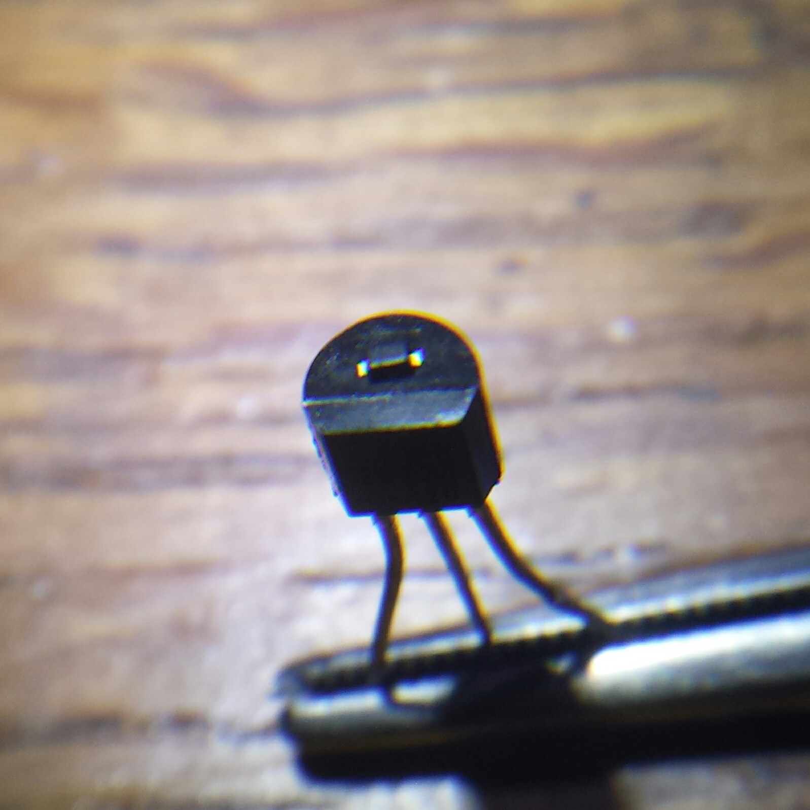
I bought some surface mount 1N4148 diodes.  They are so small I couldn’t find one when I dropped it on the bench!

Here’s a photo of one setting on top of a regular transistor.  It’s itty-bitty, teensy weensy!  It’s not much larger than a fly speck!  That’s it!  That tiny black rectangle sitting on top of what looks like a giant transistor but is only 5 mm wide.  That transistor is about as wide as a regular 1N4148, which is about 4 mm long.  The diode is only 2 mm long including the metal tabs.  Wow!

default

2017-08-29 13V Zener Diodes

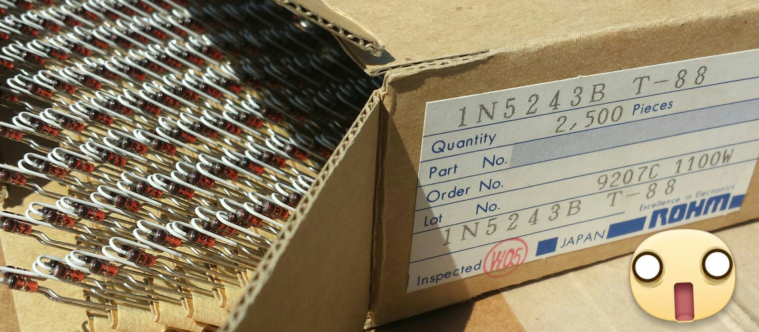
I think I have enough 13 volt Zener diodes for the rest of my life.  😱

default

2017-08-28 Am I Seeing Things?

After paying my water bill today, I left the Orange Civic Center and I glanced over to a front yard and thought I saw a funny looking black dog.  On second glance, it was a pig!  I was wondering if I was seeing things…   😱  😛  😸

default

2017-08-27 A 555 Is Easier And Cheaper Than a PIC

From a FB group post.

“primitive transistors”

I think that’s ironic.  The 555 makes the design easier for the builder.  It has all the parts so the builder doesn’t have to build from scratch.  Like making a cake using Betty Crocker’s cake mix instead of flour, eggs, etc, and no need for a recipe.  It’s the lazy way to do it.

I once got into a disagreement with others on a Usenet newsgroup about using a 555 to flash a LED.  They wanted the OP to buy a PIC controller chip, load software on a PC, learn to develop and debug software, and burn the program into the PIC, just to flash a LED.  I argued that why should he have to do all that when it would be so much easier and cheaper to do it with a 555.

default

2017-08-20 Measuring Very Low Resistance 

From my FB comment 

Some comments say measure with a meter, but fractional ohm resistors don’t measure, or barely measure with the typical ohmmeter.   Instead, you should be giving better advice.  You should use the device between your ears to find the resistance.

The resistor should be put in series with another resistor of a known value, say a 100 ohm resistor.  Then connect both across a variable DC power supply, and set it so there’s 10 volts across the 100 ohm resistor, which gives 0.1 A through both.  Then measure the voltage across the unknown resistor.  Divide it by the current, 0.1A, and you should have the value of the unknown resistor.  Simple.

© RustyBolt.Info/wordpress
CyberChimps