default

2020-01-21 Powering AC Adapters From 48 VDC or ??

I have thought about how to convert low voltage DC solar power for use inside the home. If the solar PV panels put out 24 or 48 VDC to a storage battery, the usual battery system is followed by a DC to AC inverter that puts out standard electric power, 120VAC in the USA. But the standard for low voltage power over Ethernet cable allows 48VDC at up to 15 watts to be sent over 2 pairs of a 4 pair Cat5e or Cat6 cable.

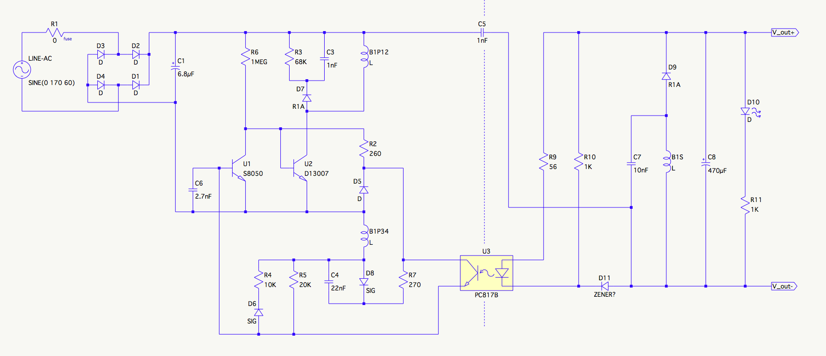
I’ve been viewing several AC to DC adapter teardowns on YouTube (Big Clive and Diode Gone Wild) and various other schematics, and the adapters are simple and are rated to work from a wide range: 85 to 250 VAC, 50 or 60 Hz. The schematic shows one that might furnish 12VDC at several watts output.

This is typical of the adapters: they have a diode full wave bridge rectifier on the incoming AC power, and a small filter capacitor rated for 400 VDC. Then the DC goes into a switching circuit that drives the primary of a small ferrite transformer. The feedback winding keeps the switch oscillating. The secondary winding is isolated from the AC line, and its AC is rectified and filtered, and sent to the 12VDC output.

The full wave bridge rectifier makes the incoming AC line inherently insensitive to polarity so it could accept DC as well as AC. It should work at full power on 120VDC, which is about what 85VAC would be after rectification and filtering (85VAC times the square root of 2). The question is what DC voltage do these power adapters stop working at? Could I get partial power from it with 48VDC applied to the power plug?

I think that if I changed some of the resistors (or put another resistor in parallel) in the circuit, it might give maybe 1/3 power with 48VDC applied to the power plug. Since it’s straight DC without any ripple, the main filter capacitor after the bridge doesn’t seem to be that critical.
default

2020-01-20 Costs of Radio Assemblies and Parts

From FB group Vintage Transistor Radios

A thought occured. Do you think that Motorola may have had a lot of parts for tube sets and they decided to use them up by putting a transistor chassis in them?

If you break down a radio into its assemblies and/or parts, which of them has the highest cost? I would expect the case to cost quite a bit because it would be contracted out to a plastic molding company or whatever. The assembled chassis would probably be the most cost, lots of labor involved. Maybe the reason why several lines of radios may have a common chassis. It would be interesting to see the Bill Of Materials for one of these old radios.

default

2020-01-18 More Zenith Royal 200 Conversion to Silicon

Continued from post 2020-01-15

I dug through my drawers and boxes of transistors and found a bunch of MPSA56 PNP general purpose on tape, and put them into the LO and mixer. I think they helped slightly – they are lower minimum fT than the 2N3906s.

I adjusted – optimized – the trimpots I had in some locations, then I unsoldered and measured the resistance. I then put in a regular resistor. The original carbon composition resistors had changed to more than 20% higher values, it wasn’t good, so replacing them has helped some, too. I still have others I should measure and replace if necessary. So far almost all of the 10% carbon composition resistors have drifted more than 10%. Some of the resistors had no tolerance band, they were 20%, but they too had drifted too much.

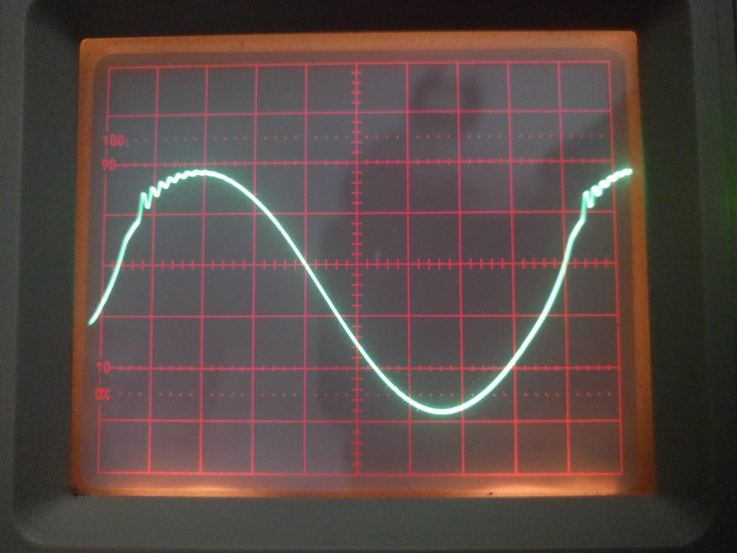
Update, later, in January. I tried a germanium PNP transistor in the local oscillator, and it put out a clean sine wave without the parasitic oscillation. I didn’t leave the germanium transistor in the LO, I put the MPSA56 back into the LO. The performance of the radio doesn’t seem to be any different.

I tried the 2N5142, a PNP TO-105 in the LO and converter stages. They work okay but the ringing is still visible on the o’scope. So I changed back to the MPSA56s. I’ve been thinking about trying some BD136 PNP power transistors in the LO but the pinouts are different, so I have to make a spaghetti mess with shrink tubing to get it to fit.

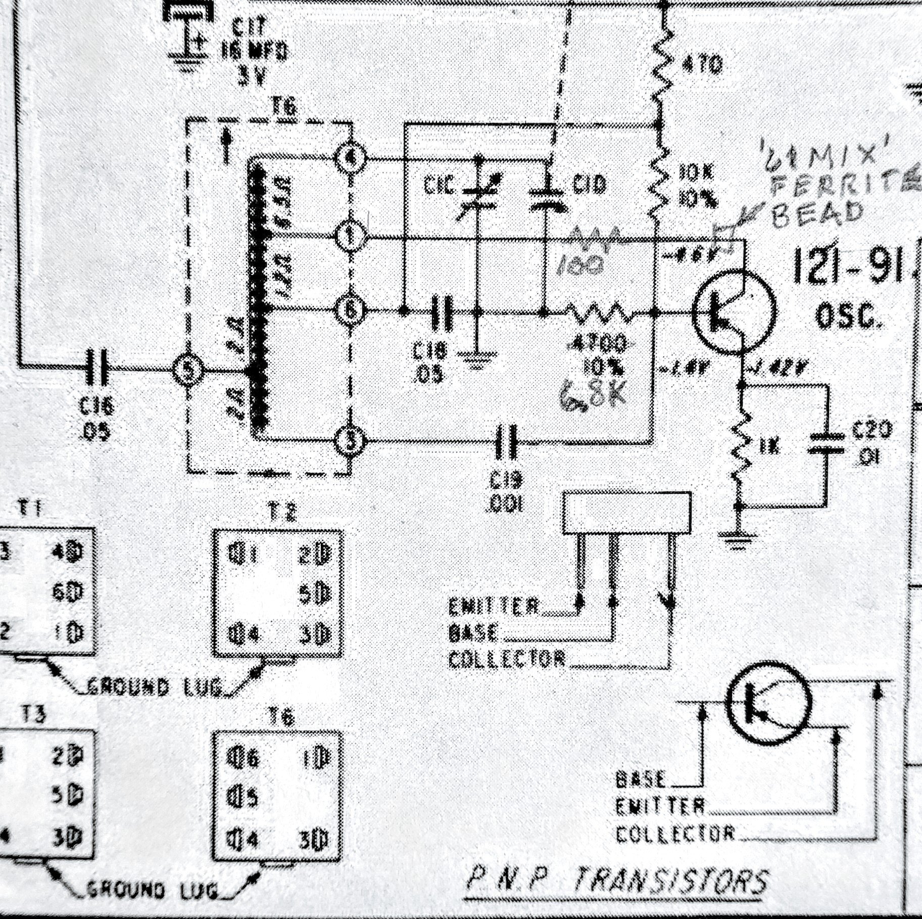
I spent some time tweaking a 1k trimpot in series with the 100 ohm and collector of the LO. If I go high enough to get rid of the ringing, the LO level drops too low. If I increase the LO level the ringing comes back. I replaced the trim pot with another resistor of about the same value. The 73 mix ferrite bead helped.

The radio is working okay. I need to stop experimenting and find a speaker for it. Then get all the pieces back together. It will never be the way it was when new, it’s still missing the tuning knob, so I used a pot knob. It has numbers but no frequencies. It’s better than turning the bare shaft. The battery compartment is okay.

default

2020-01-16 How To Remove Battery Corrosion

I took a battery holder that was corroded by leaking alkaline cells and I put it in a cup of vinegar. After several hours it came out clean, and I washed it off and let it dry. It looks pretty good now.

default

2019-01-15 Zenith Royal 200 Conversion to Silicon

I’m thinking of pulling up the end of the 100 ohm and looping the lead a few times through the ferrite bead. If that still doesn’t stop the ringing, I’m thinking about replacing the bead with an RF choke. Every time the ringing is reduced the reception gets better.  I checked to see if I had some higher inductance ferrite beads.  I found some ’73 mix’ beads and put them in place of the ’61 mix’ beads.

My Zenith Royal 200 conversion to silicon transistors is going slowly. Right now I’m working on getting a good sine wave out of the local oscillator (see photo). The waveform had high frequency parasitic ringing every other cycle. I put a 100 ohm resistor in series with the collector lead and it helped some. I pulled the 2N3906 out of the socket and put a ferrite bead on the collector lead and that helped a bit more. I lifted one end of the 100 ohm and put another ferrite bead on it, and it helped a bit more. At first only a single very strong station was received.  Now several more are heard. Before my modifications the sine wave had more ringing than in the photo. The photo was taken after my modifications.

default

2020-01-13 Slide Rule and Calculator Battery

From FB group Jan 19

Joe Haupt

In the ’80s I occasionally did work in an electrical room on campus that had a 7 foot slide rule that had been removed from the classroom. It was there for years, but the fire inspectors would make us keep the junk from accumulating in closets, so it finally got removed. 😭

I read your comment about batteries going dead in calculators. I bought a sharp LCD calculator at Sav-On Drugs back in the late 70s. The salesdroid tried to sell me 2 AA cells for it, she said the cheap Sharp batteries ‘were no good.’ I told her no. I wore that calculator out and it was still running on the same Sharp batteries years later – the current drain was so low that later they changed to button cells that last for years. 👍👍

default

2020-01-11 Reinventing the Archer’s Bow – Amazing!

So why didn’t someone think of this long, long ago?  It has so many advantages.  It’s amazing! https://youtu.be/URwuU0bRMpU
default

2020-01-10 Corrosion and Damage On Diode Leads

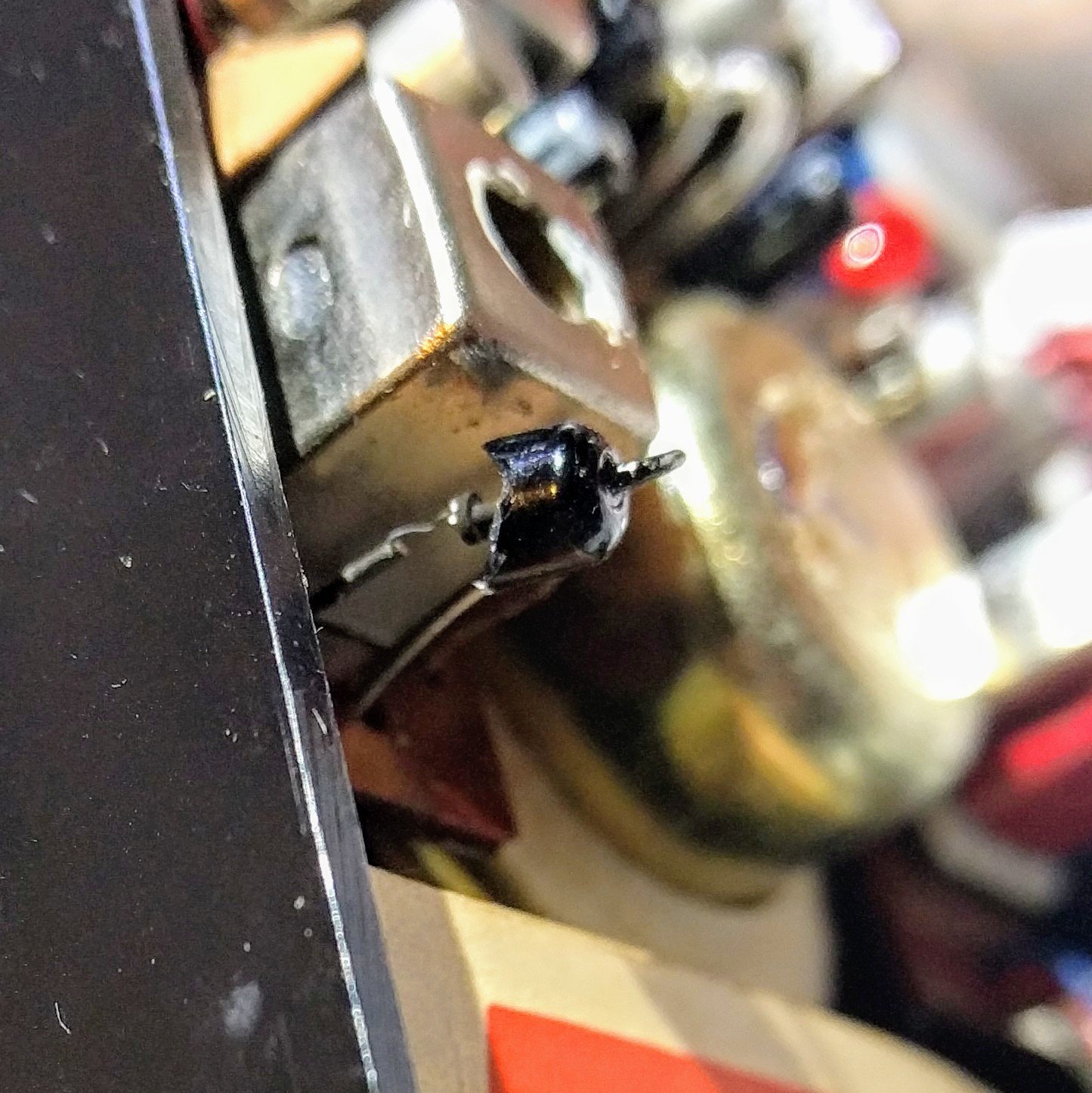
This photo is a detector diode that was broken during replacing the electrolytic capacitors.  The lead on the top was twisted, apparently putting stress on the glass package.  I replaced it with a 1N270 germanium diode.

comment from fb group Vintage Transistor Radios

Did you notice that the leads are magnetic? They stick to the speaker magnet or tools. I think they use an alloy like kovar to make the leads have the same temperature coefficient as the glass package. So the alloy has iron that rusts and corrodes much faster than copper. I’ve replaced stranded copper wire that had wicked up battery juice and was corroded inside, but it was still conducting okay. It just wouldn’t tin with solder.

default

2020-01-08 Sorting Transistors Compared to Picking Fruit

I started thinking about how the makers of transistors sort the different grades of transistors as they’re manufactured. I thought that a reasonable analogy would be similar to how a farmer might sort the fruit he harvests. Here’s what I came up with.
The farmer starts with the fruit his workers have gathered.  The fruit is first cleaned then ‘culled’ to separate the rejects out of the good ones.  These are rejected because of pest damage, non-spherical growth, too green, etc.

Then the good fruit are run through a series of different sized slots that let the fruit fall into assorted sizes.  The smallest sizes are not sellable for retail price so are sent to the processing plant where they are made into canned goods.  The largest fruit may be too easily damaged during shipping so they also may be shipped to the processing plant.  The medium sized fruit are selected for produce for shipping to retail stores.  There may be other grades selected, such as color, flavor or ripeness.

My point is that transistors are like fruit in that there are various grades that are selected from the transistors made.  Some will be too high gain, some will have too low gain.  The datasheet may give ranges of gain, such as 100 to 200 for gain range E, 200 to 300 for gain range F, and 300 to 400 for gain range G.  The transistors may be sorted into the maximum voltage they can handle, or low noise performance.  The various grades may be labeled with different type numbers according to the data sheet.
default

2020-01-06 Two Similar Transistor Radios

I posted this a few days ago.
https://m.facebook.com/groups/606087512820068?view=permalink&id=2638214152940717

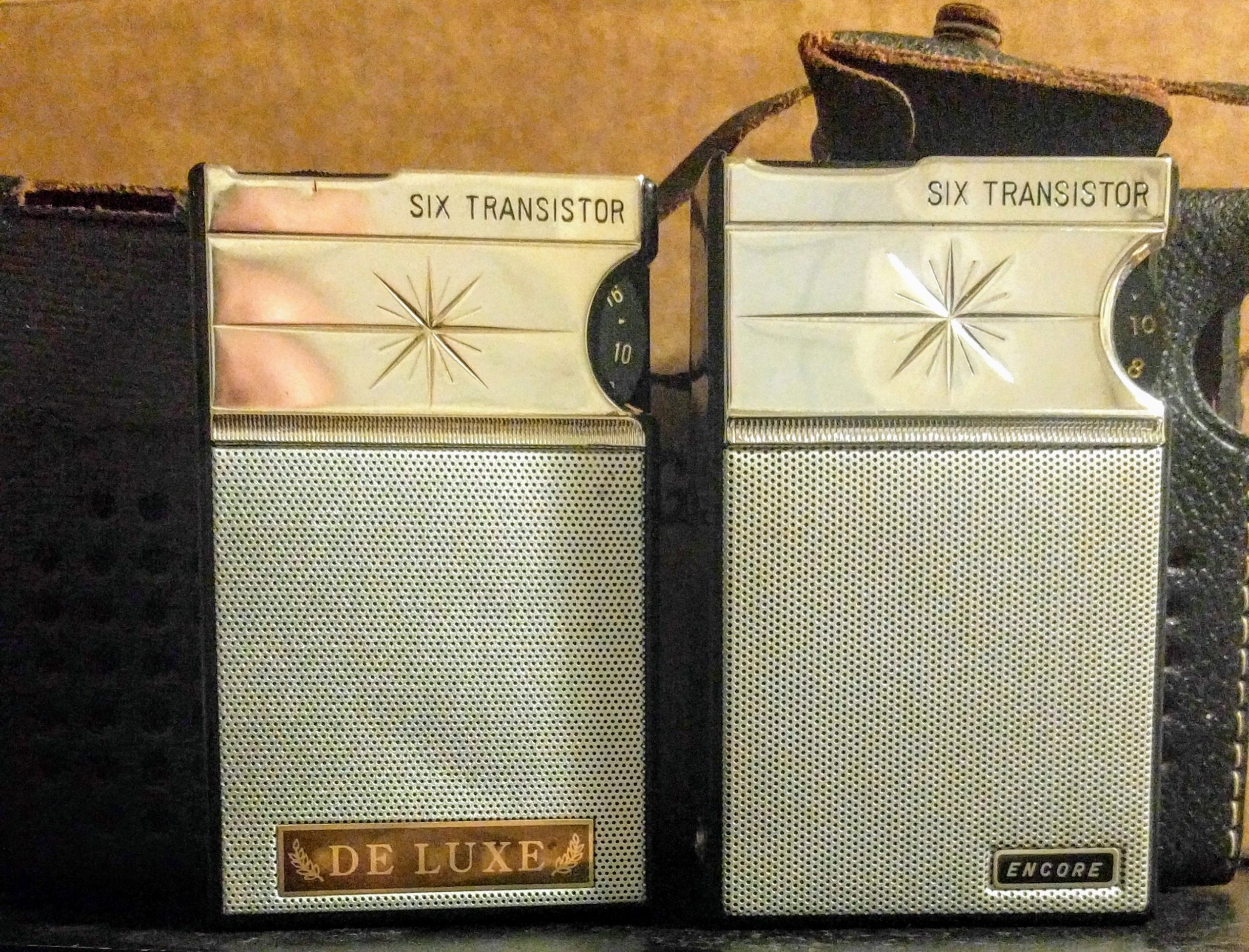
Now I’ve replaced the capacitors in another one very similar, a DE LUXE. It’s not quite as complete and in as good a shape as the Encore.

What surprised me was that some of the electrolytic capacitors were bad (measured open) and the symptom was no sound whatsoever – not even a click when turned on – as if the speaker wasn’t connected. After replacing the capacitors, everything was normal. 🤔🤔  I could see this happening if the speaker was driven by an OTL pair with an open coupling capacitor.  But this is a regular push-pull transformer output stage. 

Thanks, Joe Haupt

© RustyBolt.Info/wordpress
CyberChimps