Years ago at work (community college) we had an IBM mainframe and the terminals were connected with coax cables. We also had thin Ethernet cabling. I had the proper connectors and thousand foot boxes of coax, and most importantly the proper stripping and crimping tools. I installed hundreds of coaxes, and I was very diligent about doing the connectors correctly. My eyesight was good, but even though every connector I installed was done correctly, there was what I thought a high percentage – maybe 10% – of shorted cables. The solution was to cut off and install a new connector. The usual reason was a tiny wire of the shield had caused the short.
The thin Ethernet cabling had the same problem. So my conclusion was that when it comes to installing crimp-on coax connectors it’s a good idea to let it be done by a factory where the pros use big bench top machines that are specially made for doing the process. The cables are better quality and the cost difference is minimal.
From FB group Vintage Transistor Radios
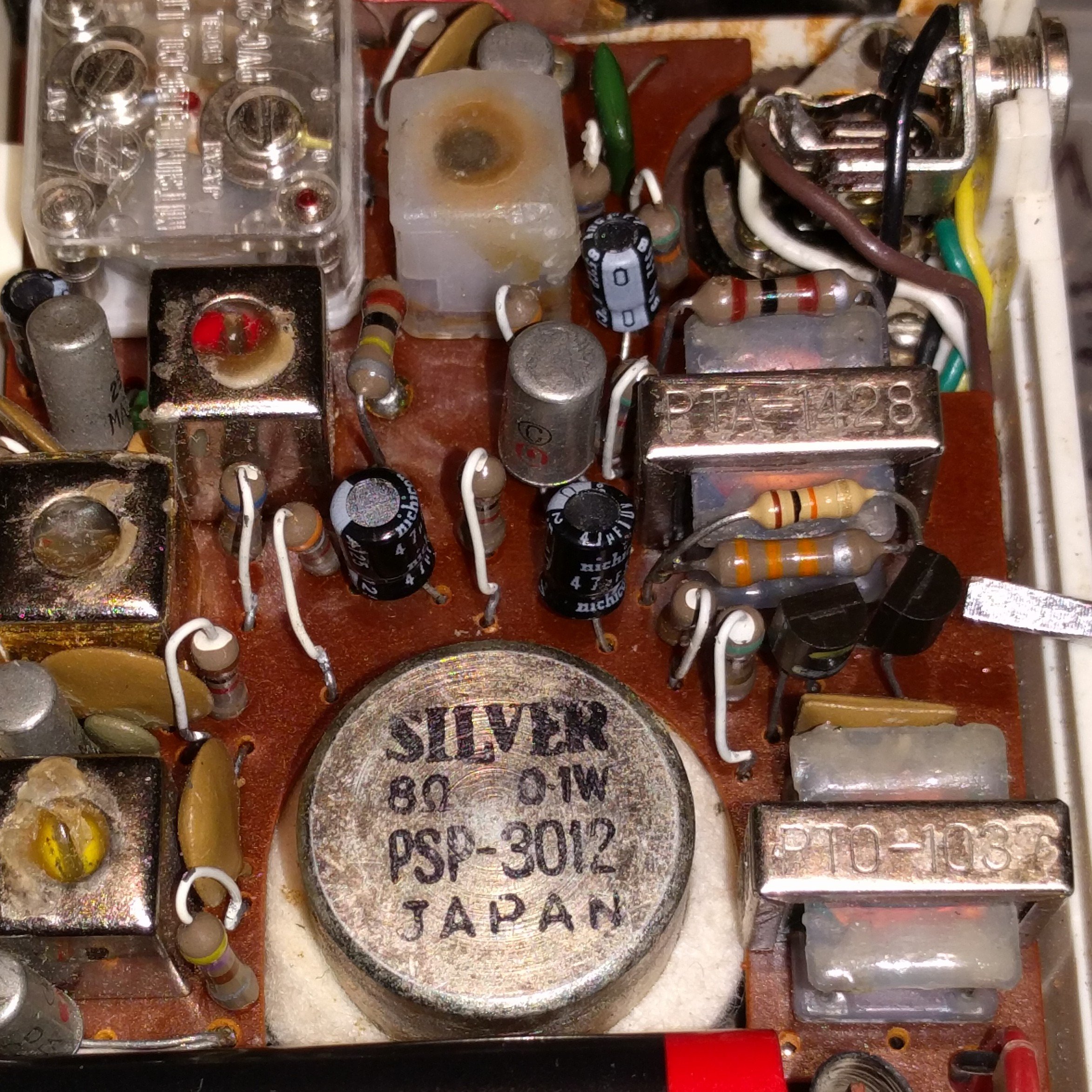
I rehabilitated this Plata 7 transistor AM radio made by Shirasuna Denki in Japan. I replaced the electrolytic capacitors, and I found that one of the germanium output transistors was shorted. I replaced both with silicon PNP transistors (the screwdriver tip on the right points to the two). Above them is a 33k (orange, orange, orange) base bias resistor. I put the 10k (brown, black, orange above it) across it to bias the two transistors to sound clean. It sounds just fine. 👍👍😁
I found the video I watched and built the circuit a while ago. This is a PSO, phase shift oscillator. If you look at the wiki for a PSO you will see that it typically has three CR elements to shift the phase (the last is a combination of the base bias resistors and the input impedance of the transistor).
The circuit he shows has four elements, and the 470 nF is part of them. He would not need the fourth RC element if the values were not so low. The Cs are typically 10 nF or less and the Rs are typically around 10 to 22k.
I built the circuit with the values he gave and it did not oscillate.
Then he varied the supply voltage and said it wouldn’t change frequency. The reason his changed frequency was because the sine wave was becoming distorted. One issue that could cause this is the base bias resistors are very low and since there is no emitter resistor, the bias is changing with the supply voltage.
He said he had experimented with the circuit, but if he had, it seems to me that he would have found the shortcomings of his bias and would have used the three CR element circuit that is the standard.
Merry Christmas…
I switched website providers more than a year ago. This week the company suddenly went out of business and everything on my blog is gone.
from FB group Building Transistor Radios 2018-11-30
I’ve done some experimenting on volume controls that are badly worn
and noisy. The idea is to substitute some resistance for the badly worn
spot. The loud crackling will be reduced and the normal volume point
will be moved to a higher point on the control. For a 5k control, I put a
470 ohm resistor between the wiper and the low or common end of the
pot. If you can’t find a replacement for a badly worn pot, this is one
simple and inexpensive way to get more life out of it.
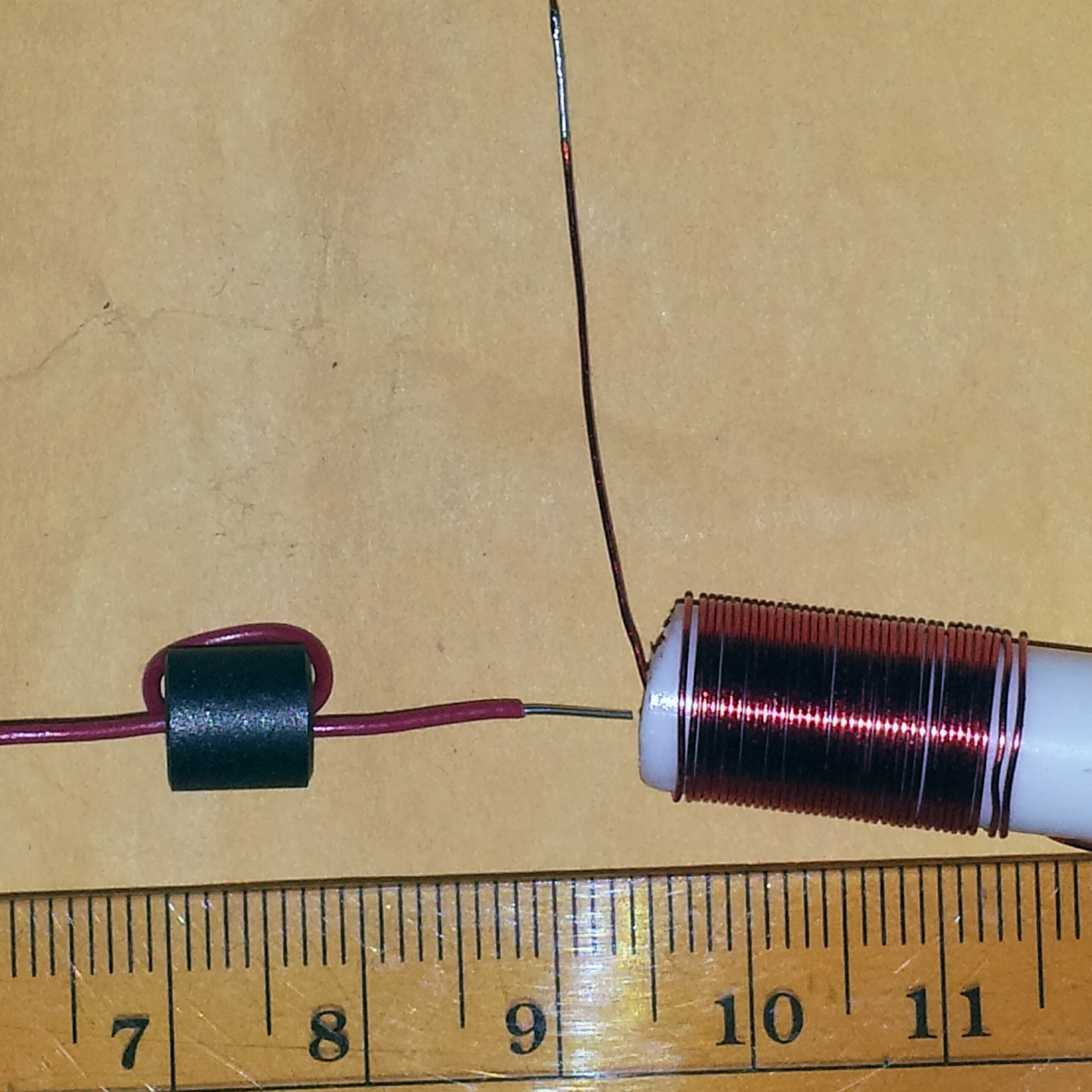
The photo shows two different RF chokes, each about 6.4 microhenrys.
The one on the left is a ferrite bead, made by Fair-Rite, Cat. #
2643000801. These were about 12 cents apiece from Mouser.com. Yes, the
wire passes through the small hole only twice and it gives 6.4 uH.
The one on the right is a piece of 3/8″ or 9mm OD Pex plastic water
pipe from the big box home improvement store. I bought a short length
for a few dollars. I cut off about 32mm or an inch and a quarter, and
heated up a straightened out paper clip wire to poke a hole through the
plastic for the wire to go through. The wire is 26 AWG solid conductor
enameled wire and is about 36 turns, close wound. I will put a piece of
shrink tubing over the windings to hold them from moving. But the
windings could be secured with clear nail polish or paint.
These will be used for RF chokes which are not critical. The RF
interference bead has low copper losses because the wire is only a few
cm long. But the ferrite core has some loss at 100 MHz. The plastic tube
and air core has very low loss but the wire is much longer and has
higher resistance.
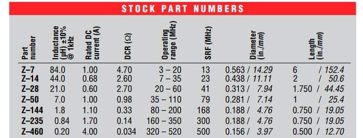
The original one, the Z-50, has a SRF of below 100 MHz, also. According to the list it’s 76 MHz.
According to my dipmeter the Pex coil is dipping at 88 MHz. That’s
just the coil, with nothing connected to it. The SRF could be raised by
reducing the number of turns and increasing the space between turns.
From FB group Building Transistor Radios Larry Daniel 2018-11-26
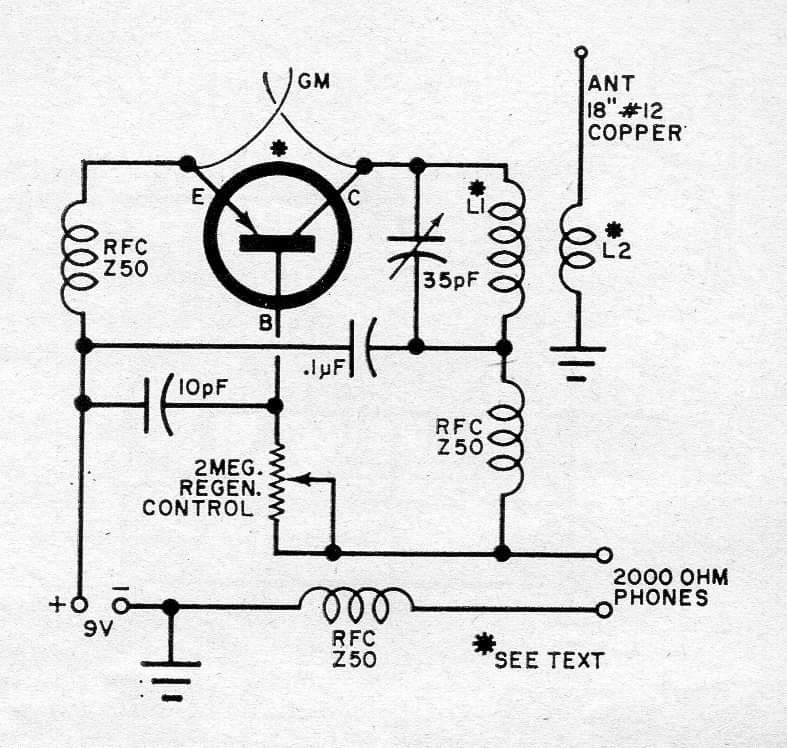
This is the original schematic posted by Larry. GM is a gimmick
capacitor made of two short lengths of solid hookup wire, twisted
together for a few pF capacitance.
List of RF Chokes for the ham bands
Larry said he used an RCA SK1008, then corrected that to SK3008. But
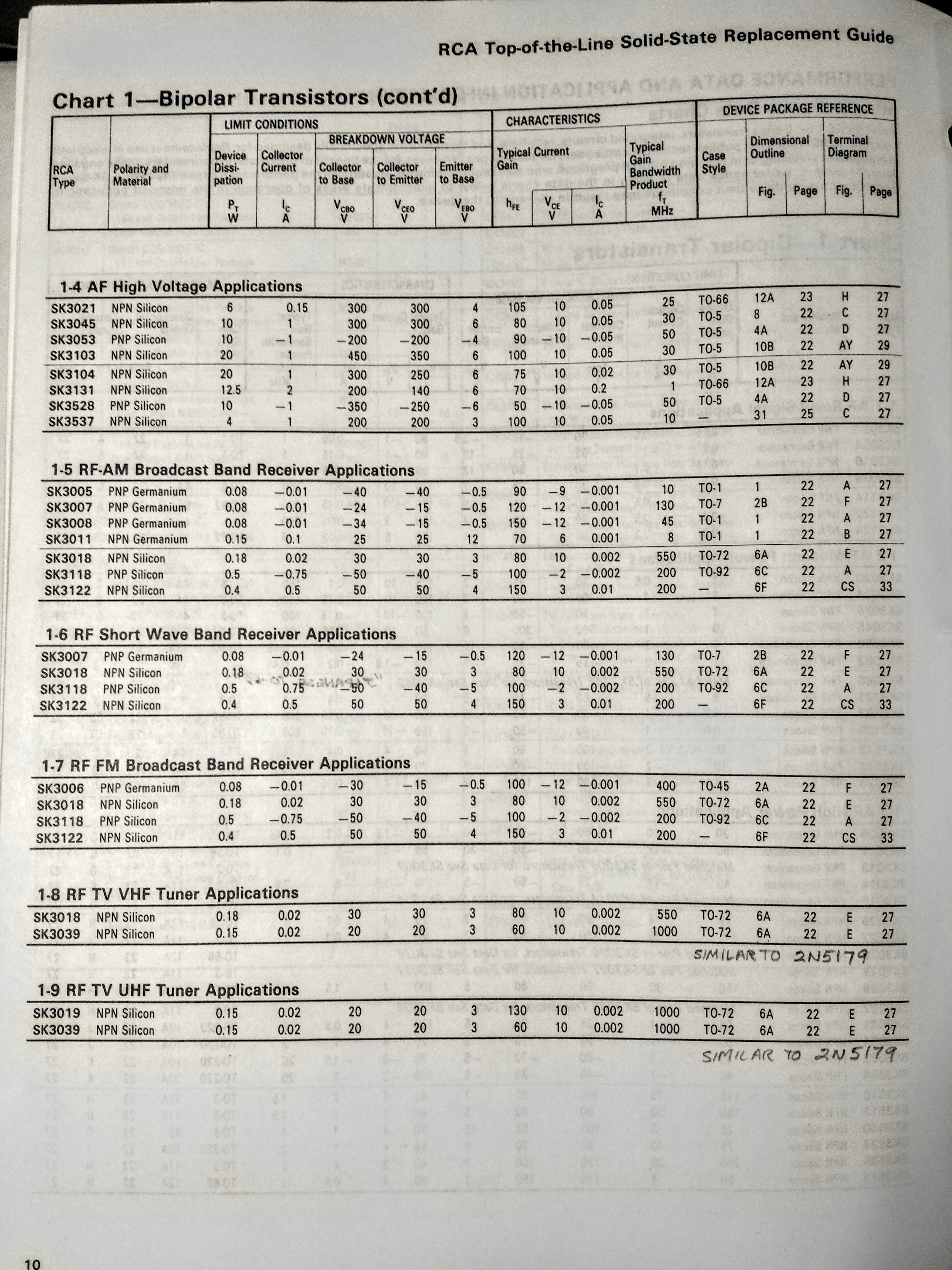
SK3008 only is good to 45 MHz according to the list, and it’s germanium
and very difficult to obtain. So battery polarity should be changed and a
2N3904 or BC547 should be used.
Scott Raschke
I used the inductor calculation tool in Electrodroid and got an RF choke
of 36 turns on a diameter of 10mm or 0.394 inch and 20mm or 0.788 inch
length. This gave about 6.8 uH, with a core equivalent to air
(permeability of 1). The AWG wire table shows 26 AWG or 0.4mm diameter
wire should fit on a single layer in that length.
The SRF of the Z50 choke was 76 MHz according to the table. The
circuit is operating at FM band frequencies or about 100 MHz. The 7 uH
choke has an impedance of about 4400 ohms at 100MHz if its self
resonance is ignored, but with an SRF of 76 MHz, the impedance will be
lower. It would be best if the choke was lower in uH value and its SRF
was higher, 100 MHz or more.
Nothing has been discussed about the tuned inductor. It said ‘See
Text’. For a 35 pF tuning capacitor it should be 100 nanohenrys at most.
That’s 5 turns 20 AWG wire on a 0.25 inch or 6.4mm form.
Larry Daniel said:
Troops, I suggested this project as a true experimenter challenge.
You do not need a lot of parts. In fact you can make most of them and
salvage the others. The trick here is by coupling the emitter and
collector via minimum capacitance you create an ersatz tunnel diode with
a bit of negative resistance. I will let the true experimenter figure
out why this might work to detect and demod a strong fm signal. The
rfc’s and gimmicks with physical placement of the signal coupling
present a true experimental transistor radio. Making this work separates
the men from the boys! The cost is very low but the potential to learn
is great! Enjoy!
I said:
Larry Daniel
I thought that this circuit was for VHF FM broadcast band. The 2N404 has
a fT ten times lower than the SK3008, only 4 MHz. The same for the
NTE100. It won’t work for frequencies above that.
The only way I could get the 2N404 cheaply was to buy them from a
notorious German dealer. Even then they were more than ‘pennies’ apiece.
For VHFs it is best to stay away from germanium and use silicon transistors.
Larry Daniel said:
“Understand Watson’s point. I just wanted to put out there a simple
transistor radio that had some challenge. BTW, I checked my working
version and the RCA germanium transistor is, in fact, an SK3008 not the
2N404 as I stated. I will not recommend any parts or values but with a
bit of experimenting you can make this radio work! Have fun!”
The SK3008 has an fT of 45 MCHz as shown in the photo of the chart. I think this transistor would be difficult to obtain.
from FB group Vintage Transistor Radios 2018-11-24
Early on, I built and upgraded many PCs when they became popular.
Some for myself and friends, but most at work. Before that I was
maintaining and repairing terminals and other equipment attached to
mainframe computers. It started out small with TRS-80s and Apples but
really took off with the IBM PCs and clones. But after many years of
competitive bids with some bad experiences we finally settled on Dell
PCs. The road wasn’t totally smooth, but we managed to keep hundreds of
PCs running despite bubblegum and soft drinks getting into everything.
It all came down to economics: It was cheaper to replace with new PCs
than attempting to upgrade. Technology changed too fast. No more Ribbon
cables, no more floppies to get full of dirt, most of the adapter cards
came on the motherboard. Everything changed with USB. And of course
there was the LAN and then the Internet. So the whole PC became less
standalone and more of a system and our job was more about
interconnectivity and less about maintaining and repair. It was some
quite amazing changes in technology.
Also posted to FB group Building Transistor Radios
Watson’s 9 picofarad homemade “gimmick” capacitor
This homemade capacitor can be used for circuits were the capacitance
is not critical, such as a wireless microphone for the FM broadcast
band. The wire can be obtained from the cable used to connect telephone
outlets. Solid (not stranded) plastic insulated hookup wire can also be
used.
I used about 300 mm or 1 foot of 24 AWG or 0.5mm solid (single conductor, not stranded) plastic insulated wire.
I cut it into 6 pieces, each 50 mm or 2 inches long. I stripped the insulation 9 mm or 3/8 inch off one end of each of them.
I took 3 of the pieces and twisted the bare wires together and soldered them. I did the same for the other 3 pieces.
I took one wire from each 3 wire piece and twisted them together
tightly using my long nose pliers. I made sure the insulation was not
damaged. I did the same for each of the remaining wires. I then had 3
twisted pairs, and two bare leads to connect to.
I checked to make sure there were no wires touching on the insulated
ends. Then I twisted the 3 twisted pairs into a tight bundle. I measured
the capacitance with an LC meter and I got 9 picofarads.
If the capacitance needs to be reduced I can use only 4 wires or 2
twisted pairs. Or I can make them shorter to begin with, or cut them
shorter afterwards. I can also untwist the wires to adjust the
capacitance and then twist them back together.
As I said, the pF value is not stable because it depends on how much
twists, and how much give there is in the plastic after you build it.
If you put it in parallel with a variable cap, then you can compensate
for changes over time.