 This was originally on my now extinct watsonseblog. I got the idea from a Youtube video, I believe it was called the Slayer Exciter. The circuit is very simple; it’s somewhat similar to the Joule Thief.
Coil
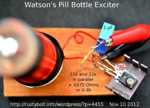
See the attached photo. The coil consists of a pill bottle that is 3-1/4 inches long and about 1 inch inside diameter. I wound on a layer of 30 AWG enameled wire, enough to cover the outside to within about 1/8 inch (4mm) of the ends, and I taped the wire at the ends to hold it in place. I could still fit the bottle cap on the bottle. At the top of the coil (bottom of the pill bottle) I drilled a 1/8 inch hole and put a 4-40 by 1 inch screw, head inside of the bottle and a nut on the outside. I stripped the enamel insulation off the wires on both ends and wrapped the top end wire around the screw threads, and tightened a second nut down onto the first nut to hold the wire. This will be the high voltage terminal.
I wound four turns of 20 AWG (the heavy red wire in the photo) at the bottom (cap end) of the coil, and I taped it with black electrical tape to hold it. I left about two inches (50mm) of wire loose to make the connections to the circuit. I mounted the bottle cap to a small piece of wood with a screw to hold the coil upright, Tesla Coil style.
I mounted a BD135 NPN transistor to a small heatsink (I later changed this to a BD433 to handle more current and power). I soldered the bottom (cap) end of the heavy red wire to the positive side of the bypass capacitor (blue cube in photo). I soldered the other end of the heavy red wire to the center (collector) lead of the transistor (spreading the transistor’s legs apart helps prevent shorts). I soldered the other side of the bypass capacitor to the emitter leg of the transistor (see photo). I soldered the base leg of the transistor to the 10k and 22k paralleled resistors (I should have used a 6.8k instead). I soldered the other end of the resistors to the positive of the bypass capacitor.
I soldered the cathode (flat spot) lead of the red LED to the base lead, along with the thin red wire from the HV coil. I soldered the LED’s other anode lead to the emitter and negative. This seems backwards, and it is. The LED does not come on when the base voltage is positive, but comes on when the base voltage goes negative more than two volts, protecting the base to emitter junction against excessive negative voltage – that’s the whole reason why it’s there.
If the HV electrode doesn’t have HV or the LED doesn’t light up, and the supply current is low, it is probably not oscillating. The cause may be that the winding with the heavy wire is connected backward. It may start to oscillate if the two heavy wires are swapped. But mine oscillates with the winding end closest to the cap connected to the positive supply. Looking at the coil from the top, mine has the HV winding wound clockwise from the bottom to top. The primary or heavy wire is also wound clockwise from the bottom.
Performance
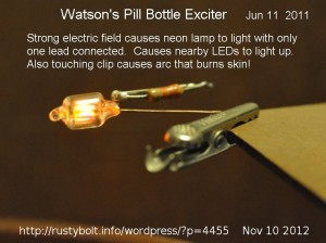
The screw on the top end is the HV electrode. I started out at 1.5V and cranked up the voltage to see how it was going to work. 5V gave me enough HV to light up a CFL light. I got up to 8 volts and the current was around 200 milliamps but varied greatly with the load on the HV electrode. The LED also lit up dimly or brightly depending on the load. I could touch my finger to the HV electrode and see a very small spark, and smell the smell of burnt flesh, and see a spot on my finger. Sometimes I could feel a sting. The small heatsink got warm, but not hot.
An Improvement??
The videos on Youtube show some experimenters inserting a core into the coil, such as a ferrite toroid. I have a handful of the Goldmine G6683 toroid cores, that used to be five for a dollar but are no longer in stock. They are 25mm (.983″) O.D., 13mm (.508″) I.D., and 9mm (.354″) H. I taped two of them together and put them inside of the pill bottle at the base where both windings are. This changed the inductance but I didn’t notice any change in performance.
WARNING
In my experimenting, I only used about 8 volts on the circuit. Some others who are much braver and IMHO more foolish used voltages 12 or maybe more. You should remember that when the voltage is increased 41 percent, the current is also increased by 41 percent, and you are doubling the amount of power into the circuit. This is pushing the transistor closer and closer to the brink of destruction, and it is advisable to have a reasonably large supply of spare transistors on hand if you’re going to play this risky game.
The transistors I’ve used with a Joule Thief are meant to be used in low voltage, high current applications. The exciter demands much higher voltage performance, and this will exceed most Joule Thief transistors maximum ratings, not to mention they would get extremely hot very quickly.
Some have managed to get high enough voltage from the HV winding to cause the corona discharge, the blue glow around the terminal that can be seen in the dark. One other thing that might help is to get a good quality capacitor and use it in parallel with the winding to cause the circuit to resonate, and it may help increase the spark. This is what is done in the older Kettering type of ignition coils used in cars with points and a ‘condenser’ which is the capacitor, across the points. The value of this condenser is typically 0.2 uF.
Back to experimenting…