default

2012-10-29 1W LED Light – Micropuck

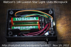
I built this light several years ago.  I bought a LEDdynamics Micropuck 350 mA LED controller to drive a Luxeon Star 1W white LED.  I used a black plastic project box, might have been from Radio Shack, as the case.  I sawed the case in half, heightwise, so that it would fit in my pocket.  I cut a cover from a sheet of clear plexiglass (not shown in the picture).

The Micropuck is the small cube with the white label to the right of the battery clip, between the orange and green wires and the red and black wires.  The red and black wires coming out of the bottom go to the battery holder and switch.  The orange and green wires connect directly to the LED.  Yes, I know the wires in the case are a bit too long, but hey, they’re not hurting anything. I sawed off the switch’s handle to make it more difficult to accidently turn on the light.

The Luxeon LED is fastened with 4-40 screws and nuts to a thin strip of copper.  It has the lens that is not a hemisphere, it’s shaped more like a pill.  This gives a widely dispersed beam, as can be seen in the picture.   It made the light useful for closeup stuff like reading or working on a PC board.  As would be expected, the light is hard on the AA cells, so I didn’t use it much, or else used it with rechargeable Ni-MH cells.  I very seldom used a store-bought circuit to drive my LEDs; most of them were built from scratch by me.

Back to experimenting…

default

2012-10-28 Joule Thief Circuit From 1960

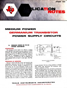
I took a picture of this old application note from Texzs Instruments dated 1960.  The circuit uses a germanium transistor, and adds a third winding to the coil to get high voltage (800 volts).  If this third winding is removed and a LED is placed across the Q1 collector and emitter, and the supply voltage is reduced to less than the LED V, then it would be essentially a Joule Thief.

They used two resistors in a voltage divider to give the transistor base bias current.  One thing that we should remember is that the germanium transistor could have an emitter to base reverse breakdown voltage as high as the collector breakdown voltage.  Today’s silicon transistors are typically rated for 5 or 6 volts, not any higher.  This is not a problem when the supply voltage is only a volt or two, but if the supply voltage goes above 5V, then the circuit could put the same negative voltage on the base, so the transistor must have some way to protect it from excessive reverse E to B voltage.  The ratio between the windings can be changed so that the feedback winding gets a reduced negative voltage.  Or a few diodes or LED can be put between emitter and base to shunt excessive voltages.  However this wastes some power, which is not desirable with a battery operated circuit.

default

2012-10-27 Cheapo DMM Battery Conversion

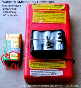
The hundred plus dollar DMM (digital multimeter) I use on the bench has an auto shutoff when it’s not being used, but the cheapo Cen-Tech DMMs from Harbor Freight do not, so if we forget to turn it off (and even the best of us do), then the “Extra Heavy” 9V battery that comes with it (see picture) soon runs down and the meter’s low battery warning indicator comes on.

I ruminated about making a 3V to 9V converter a few weeks ago to solve this problem.  But I have a couple packs of CR123 cells lying around without a flashlight to use them in (I gave them all away), so I decided to go the easy route and connect three of them in series and fasten them to the back of the DMM.   They have a much higher capacity than the cheap “Extra Heavy” 9V battery, or even an alkaline battery, which costs about half the cost of the meter itself, which is sometimes on sale for $4 at Harbor Freight.  I will not have to buy another expensive 9V battery for my meters ever again.  I’ll just use up the CR123s instead.  I got these CR123s for cheap from dealextreme.com, a little over a dollar apiece with free shipping, but if you buy more you can get a discount.  You may think that I’m spending over three dollars and that’s what a 9V battery costs, but these three cells should outlast the 9V by several times.  In the long run, the power from these is still much cheaper.

I taped three of the CR123s together with adhesive tape, and soldered a short piece of wire between the positives and negatives.  Then I drilled two small holes in the back of the DMM to run the wire through to hold them in place.  I used a snap on 9V battery connector, but the red and black wires may not agree with the polarity of the battery.  The smaller contact must be the positive terminal, so make sure you test it with a meter before you plug it in. IMPORTANT!  If it’s backwards, the DMM might be damaged!

I filed a groove in the side of the case and cover to let the wires pass through.  The black electrical tape was the last to go on  – three layers of it to prevent shorts.  Then I screwed the screws into the holes on the back to hold it together.

About the only disadvantage I can think of with the conversion is that the lithium cells can catch fire if shorted.  That’s why I put the black electrical tape around the outside: to cover the contacts and prevent shorts.  Also, it will give some protection against high voltage shock if I happen to be measuring HV with the meter.  The exposed cells could be at high voltage if the leads are in contact with HV.

Back to experimenting…

default

2012-10-26 Salt Water Battery Runs Joule Thief

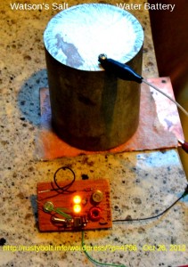
I have this billet of magnesium that I’ve used for a number of things including a door stop.  It’s rather light for its size, and the metal is soft, like aluminum.  But the chips from drilling burn with a white light.  It really is magnesium.  I drilled a small hole in it to screw a screw in for a terminal to clip my clip lead on.

The battery consists of the magnesium billet on top, two pieces of paper towel to hold the salt water “electrolyte” and prevent the plates from shorting, and on the bottom is a piece of printed circuit board, which serves as the copper plate.

I put the paper towels on the PC board, wet them with the salt water and set the magnesium on the paper towels.  The two Joule thief LEDs lit up brightly for a second, but the brightness  started to taper off over the period of a few tens of seconds.  Open circuit voltage was 1.3 volts but fell to less than 0.6V with load.

The Joule thief uses a 2N525 germanium transistor (ETCO has long been out of business since the 1970s?) and two yellow LEDs in series.  The voltage across these LEDs is greater than the voltage of a single LED such as white or blue, so if I connect an LED to the green and black wire leads, it will light brightly and the yellow LEDs will go out.

Later I got some lime slices and put the juice onto the paper towel.  It seemed a bit brighter than the salt water, but I could not be sure without doing some measurements.  Problem is that the current is constantly changing as the electrolyte gets used up.  Here’s a cool battery lighting a LED.

Back to experimenting…

default

2012-10-25 One Coil LED Oscillator Circuit Very Bright…

I came across this single coil, two transistor circuit on Youtube and found it interesting because it uses a touch pad.  This circuit is the same as many other two transistor V booster circuits, often mistakenly called Joule Thiefs (see the schematic in the video).  But with one exception: it uses a 0.2uF capacitor that is very much larger than the typical circuit.  The large capacitor is two thousand times higher value than the typical 100 pF capacitor that is typical for this circuit.  The higher value capacitor pushes the circuit into “squegging” which makes it look like it is flashing.

The circuit’s two transistors have enough current gain so that if a high resistance is substituted for the 2k resistor, it will still work.  A typical pair of fingers touching the touch pads will have a resistor from tens of thousands of ohms when moist to hundreds or thousands of kilohms (more than a megohm) when very dry.  The few microamps through the fingers is amplified up to tens of milliamps at the collector of the PNP transistor.

The author used an expensive 3W white LED, but the circuit is severely crippled and unable to deliver more than ten or so milliamps to this high power LED due to the BC557 output transistor.  A considerable increase in LED current could be obtained by using a BC327-40, or better yet use a seriously high current transistor such as a 2SC2500D, KSC5041, or NTE11.  But with the BC557, he might as well remove the 3W LED and put a regular 5mm white LED in its place.

Whatever transistor is used, the coil should have a DC resistance of less than 1 ohm, preferably less than 1/4 ohm at very high currents.  When the NPN is used for the output transistor, the other transistor must be switched to a PNP, and the polarity of the battery, LED and capacitors (if they’re polarized) must be changed.

default

2012-10-24 Presidential Debates

After the presidential debates are over (and not having watched them), I have one thing to say:

Intelligent people don’t make a choice of president on the basis of sparring matches.

That being said, I quote

Never underestimate the power of human stupidity.” — Robert Heinlein

default

2012-10-23 LED Lifetime – Disappointing

This agrees with my own experimental findings.  This is why I’ve been buying the Philips LED lights.  They seem to hold up best under long term tests.  I think he made a good choice of using the Nichia LEDs, they are good quality and seem to hold up long term, too.   Anything else is likely to die a slow death.

LED logger

default

2012-10-22 Greenwave Wireless Networked LED Light Bulbs

This Greenwave Reality (their website was s-l-o-w) is something that could be the future, but the price at this time may be prohibitive.   If the price can be lowered then more home owners will be attracted to this really cool product.

I bought a Stanley three station wireless power outlet controller.  I got a little fob with three sets of on/off buttons, and three adapters.  It is very convenient to be able to control these lights with a remote control, especially when they are not even in the same room.   I’m seeing 5 station sets on Amazon for $30.   Now if I could just get the adapter that would fit between the socket and lamp, I would have essentially the same thing as this Greenwave.

Another product that is available is X-10, which can be purchased from their website. It has wireless capability and interfaces to the PC.

default

2012-10-21 Solar Powered Garden Lights – Ideas

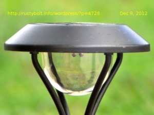
I got to thinking about solar powered garden lights, and it suddenly dawned on me.  I have never seen one as simple as the common as dog doo-doo flashlights that use three AA cells.

I’ll have to start with what I have observed in the limited number of garden lights that I’ve opened up and looked at the circuitry.  All of them that I can remember have been using a Joule Thief or similar V boost circuit to boost the voltage of a single rechargeable cell.  Yet when I look at the impulse items at the checkout counter, I almost always see cheap flashlights that use three AAA cells.  They almost never use a single cell with a boost circuit, presumably because they are trying to make them at the lowest possible cost (they don’t have to include batteries).

Why didn’t the garden light designers use three rechargeable AAA cells instead of a single cell?  Just think about it.  With three AAA cells, the flashlight – and garden light too – would not need a V boost circuit.  Eliminating that would save some, however there would still need to be a resistor to limit the LED current and a diode to prevent the batteries from discharging back through the solar cells.

It became apparent to me that there must be something else that was determining this, and then I concluded that the determining factor must be cost.  The cost of three rechargeable cells, which the maker must supply, are more than the cost of the V boost circuit.  And also there must be more solar cells to charge the batteries at 4.5 volts than at less than 2 volts for a single rechargeable battery.

Another thing that also occurred to me.

If I built my own solar garden light, I could use three rechargeable cells, and eliminate the V boost circuit, and get better performance, too.  Since the Joule Thief or other V boost circuit eats up almost half of the power put into it, eliminating it would increase the efficiency of the light.  I could then get more light, either by putting more current through the single LED, or putting more LEDs in the light.  The solar cell would have to supply 4.5 volts, but that would be easy to do since most solar garden lights are so cheap I could scrounge two cells and put them into my solar light.  Or I could keep the two lights and connect them so that their solar cells are in series, and thus able to charge more cells.

Back to thinking up more brilliant ideas…

default

2012-10-18 Ginormous Ultracapacitor – 2600 Farads

I once had this blogged in my watsonseblog, but I haven’t blogged it here.  I’m trying to charge this Maxwell ‘Boost Cap’ or ultracapacitor with a solar cell, but the problem is that this cap is so ginormous that it takes a very long time to charge when the solar cell is putting out 100 milliamps or less.  That assumes a bright sunny day, even longer when it’s cloudy outside.


© RustyBolt.Info/wordpress
CyberChimps