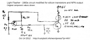
 I continued on with my experiments using the BD433 by building a Light Flasher. This flasher is a very old design which originally used germanium transistors. It also predates LEDs, so it used a standard #1850 miniature lamp or incandescent light bulb. Instead I used LEDs, so I had to allow a small current to bypass the LED during the off time, to prevent the LED from glowing dimly. I did this by putting a 4.7k resistor R6 across the LED.
Also, because the original used germanium transistors, which are lower gain and somewhat leaky, the resistances were lower than needed for silicon transistors. So I changed R1 and R2 to ten times their original values, 47k and 82k. I increased R3 from 3k to 33k, and decreased C1 from 250 uF to 22 uF. R4 stayed about the same, 82 ohms. R5 was originally 820 ohms because the germanium transistors tend to be leaky and this low resistance minimized the base current leakage. But a silicon transistor would probably work just fine without it, so instead, I put a 22k there. Any resistor from 1k to infinity may work without problems. As I said, R6 across the LEDs was 4.7k. For Q1 I used a 2N4403, and for Q2 I used the new BD433 transistor I just bought.
I built the circuit on a postage stamp sized piece of perfboard. The BD433 is conducting high current, but is fully on or off almost all of the time, so it does not get warm. But the current is very high; the power supply I used was capable of supplying 1 amp, but the voltage dipped with each flash, indicating that it was going into current limiting. I set the power supply to 5V, even though it originally used 6V. I connected up the LED assembly from a 9 white LED flashlight from the 99 cent store, and also a green 1 watt Luxeon Star LED in parallel. Even though the forward voltages of these two are very different, they both light up very brightly because the current is so high that the peak voltage drop across the green LED is more than 3.3V, and part of the current then goes through the white LEDs.
The flash rate was about 1.4 Hz, or ten flashes every seven seconds. The project was successful the first time I powered it up. The BD433 makes a very good choice; it handles the very high current pulses easily.
Other thoughts – It might help if there was a 10 000 microfarad bypass capacitor across the supply at the point where the leads are on the perfboard. this should reduce the very high peak current the power supply has to supply. The 1.4 flashes per second that it has right now is a good speed, and does not have to be modified. However the 33k resistor could be replaced with a 10k resistor in series with a 50k variable resistor AKA trimmer, so the flash rate can be adjusted. The pulse rate is short, and this flasher with only the white LEDs would make a good stroboscope if the speed was adjustable. It could be used to freeze motion, of a rotating wheel for example. Another cool thing to do is to have it illuminate someone with flashes while they go through motions, I’d guess this would be called multiple exposures.
An advantage of this design is that the flasher circuit is totally contained between the two wires, and requires only a connection to the light bulb and to ground or negative. This simplifies the wiring.
For much higher power, this circuit could be connected to a relay (put a 1N4003 across the relay, cathode to positive). The relay contacts then could control a very high current or high voltage. The relay would have to have fast acting contacts because the pulses are short. The more I think about it, the less I like this relay idea. First off, the relay may be too slow. Then there’s the constant clicking of the relay. And one has to consider how long the contacts will last when they are constantly turned on and off. All together, I think I’d skip the relay idea and instead use a high current transistor or MOSFET on a heatsink instead.
My blog with a schematic of another light bulb flasher.
Back to experimenting…