default

2017-07-07 Excessive ELF EMF

From FB comment
There were 4 main breaker panels in the electrical room inside, 3 rated at 1200 amps and one rated at 3000 amps.  My shop was on the other side of the wall, and I could put a CRT type monitor against the wall and the 60 Hz magnetic field caused the monitor to display a wavey picture, enough to make one nauseated after awhile.

I measured the field with a ELF gauss/tesla meter, and it went offscale!

default

2017-07-06 “Minimalist” Regen Receiver QRP-Gaijin

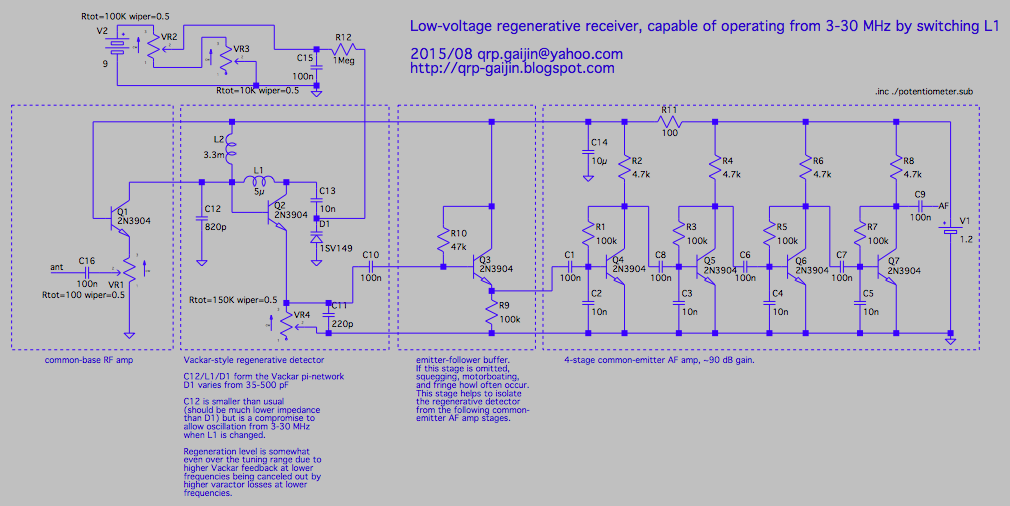
I was reading this blog, and I’m referring to this schematic. The author calls this regenerative receiver a “minimalist” design, but I refuse to consider a circuit with 7 transistors minimalist. If one thinks of the design as constrained to using a supply voltage of only 1.2 volts, a single AA or AAA rechargeable NiMH cell, then it is a design compromise. There is no reason why a higher voltage – more batteries, or a V boost circuit can’t be used to supply a higher voltage to the circuit. In fact, the circuit uses a 9V battery to tune the voltage variable capacitor. This could be used and the 1.2V battery eliminated.

The author stated that the emitter follower (first audio) stage is to prevent the circuit from acting erratic. There are four stages of voltage amplification, apparently because the gain of each stage is too low, apparently because the supply voltage is very low. I guesstimate that the emitter follower stage and two of the four audio amp stages would not be needed if the supply voltage was higher. And with four transistors instead of 7, I would consider the circuit more minimalist than his original circuit.

To get a higher supply voltage, one of several methods could be used. The NiMH rechargeable could be replaced with a lithium rechargeable, which would give a supply voltage of 3.6 volts. That’s 3 times as much. Or the battery could be 2 or 3 NiMH rechargeable cells in series, giving 2.4 or 3.6 volts supply. Both of these completely eliminate 3 transistors and their associated parts, at least a dozen parts.

A voltage boost circuit could be used. But these typically operate at high frequencies that might interfere with radio reception. So it could take several parts to isolate and reduce the interference. The switched capacitor V boost chips are less interference than the circuit that uses an inductor.

I noticed that the last 3 audio amplifier stages are connected to the battery, without a decoupling capacitor and depend on the low impedance of the battery to prevent positive feedback through the DC supply. This is a violation of good design and could be the reason why the author found that it was oscillating – ‘motorboating’. There *must* be a 47uF or more capacitor in parallel with the battery.

More details to come…

default

2017-07-02 Fixing Problem – TV Too Loud

I managed an apartment complex and we had a nice elderly lady living there.  But she had a habit of turning the TV up too loud.   I worked with this lady’s (adult) son to solve the problem.  His mom was disturbing the neighbors in her apartment bldg.  So I went inside the TV and added a resistor in series with the hot end of the volume control.  This limited the volume to a lower level.  That helped a lot to stop the complaints.

default

2017-06-28 Detecting Bad Alternator Rectifiers 

From comment left at a blog for a battery voltage monitor project 

I think this is a great project.  But I’d like to relate to you all how it was done in the past, when alternators started replacing generators.  Back then the rectifiers were not as rugged as now, and sometimes a rectifier diode would fail.  The battery might get charged enough, except when driving at night with the lights on.

This could sometimes be heard in the car radio’s speaker as a whine sound that changed pitch with the engine speed.  So someone came up with the idea to use an earphone or small speaker with a 100 uF, 25V electrolytic capacitor in series.  Just connect it with the correct polarity to the battery while the engine was running.  The whine with a normal working alternator was very quiet, but a bad rectifier could be easily heard.  This made a good tool for finding a bad rectifier diode.  Someone should make a tester using this method.

default

2017-06-27 Pres Does Take His Salary, Donates It, Government Loses

Quote from a mailbag:

“One reader took issue with our In the Works rating for Trump’s promise not to take a salary. We noted that at the White House press briefing on April 3, press secretary Sean Spicer announced that Trump would be donating his full first-quarter, pre-tax earnings of $78,333 to the National Park Service.

The reader wrote, “There is a difference between taking no salary and taking a salary and donating it to charity. The difference is that he gets a tax deduction for his donation. As such he, does profit from his presidential salary. In addition, the government is still out the amount of his salary plus the tax deduction. As such, the U.S. government will lose more than if he just pocketed his entire salary.”

default

2017-06-26 Atomic  Myths, Etc .

Re: the efficiency of electric lighting systems, that’s very low. This was written before LED lights had become widespread, so I wonder what the number would be today.  Probably somewhat higher.

From https://ieer.org/pubs/atomicmyths.html

Also see https://ieer.org/resource/carbon-emissions/electric-future-nuclear-carb-diet/

The average efficiency of electric lighting systems is about one percent – that is, only about one percent of the energy in the fuel used to generate the electricity comes out as visible light energy. The rest is wasted as heat either at the power plant or in the light bulb. Even high-efficiency lamps have an efficiency of only about three percent.11

Passenger transportation efficiency is similarly dismal. The useful work done when a car weighing 1.5 tons transports one person weighing 150 or 200 pounds is typically about one percent or less of the energy content of the fuel input, even if one does not take into account the fact that much of the driving is typically done to earn the money needed to purchase and maintain the vehicle.12″


default

2017-06-25 Mini Audio Transformer From Goldmine Electronics 

I bought several of these miniature audio transformers  from Electronic Goldmine.  They are encapsulated so I can’t see anything, windings, core or materials.  There are 5 pins, 2 on one side and 3 on the other, but the center pin measured open, so it’s apparently there to make sure the transformer is inserted the right way.

The ad says 0.45 henry per winding, and both windings are the same so the turns ratio is 1 to 1.  My tester says both of the windings measure 1.44 henry, so I’m not sure what the exact value is.  I’m going to measure it with another meter to see.

From what I can guesstimate judging by other known audio transformers, this one should have an impedance of around 2000 to 6000 ohms.  The windings are slightly different DC resistance but that’s because the inner winding has less circumference per turn than the outer winding – even though both windings have the same number of turns.  The wire length is slightly shorter and slightly less resistance.

I’m curious as to how they determined that these transformers are audio.  They could be for pulse generation and have a ferrite core for frequencies in the tens to hundred kilohertz range.  At those frequencies the winding impedances would be high.  My thoughts are that this transformer might be used to isolate the powerline side of a SMPS from the low voltage and controller side.  This is usually done with an optoisolator, but a transformer can also be used.

I’m wondering if it would be worth opening one up to see what’s inside.  I used a propane torch to reclaim the toroid cores from potted transformers, I just burned away the plastic until a core with charcoal and wire was left.  I don’t know if the core on this audio transformer is ferrite or laminations, but it’s very small and light, so laminations would be very tiny and light.  

default

2017-06-24 WWVB, Phase  Modulation and LaCrosse Clock

From FB comment to Bill Sherman’s atomic clock’s damaged LCD 

At our computer club one of our members talked about this.  Over 3 years ago NIST added phase modulation to WWVB.  Only one of the makers of ‘atomic clocks’ has just come out with a clock that demodulates this phase modulation.  LaCrosse has a wall clock, and he showed us the one he bought.  It’s a hundred times more sensitive than the older clocks, so it will receive the signal even when the clock is on an inside wall.  His house has the attic insulation with a layer of aluminum foil, and his other clocks won’t pick up the signal unless they are on an exterior wall.  But this new clock works anywhere.

default

2017-06-23 Transistor Tester Arrived

I received the transistor tester that I ordered a week or so ago.  I ordered this one preassembled (the price was only a few dollars more) and with the plastic case, which I have to assemble.  I ordered it from a seller on eBay for $20.

This is different than the component tester I bought last year.  This one has a green ZIF socket with the lever, a digital volume control in the lower right corner, and a color OLED display.  It also has two terminals above the display, and two sets of two terminals at the lower right corner.  The green ZIF socket has a mark above it on the circuit board showing the pin arrangement.  In both rows, the fourth pin is pin 2, the three to its left are pin 1 and the three to the right are pin 2.

I got some parts and started testing a few.  The first was a 625 ohm, 0.05% wirewound resistor.  This is super accurate, to within a third of an ohm.  The tester was also accurate, to within the same 1/3 ohm.  So that’s a very good sign!  But then the screen kept saying that it was not calibrated, and to short the three pins together and calibrate it.  It gave a website to get more information.

The website looked like it wasn’t correct so I went online and searched for transistor tester, and came up with several hits, so I clicked on a YouTube video of how to use it.  The guy showed how to short the three pins and get into the menu and start self test.  After I did that it no longer said it wasn’t calibrated.

The inductance test cannot resolve inductance less than .01 millihenry, which is the same as 10 microhenrys.  The resistance and capacitance tests seem to do better.

The tester said there was a 0.1 uF calibration capacitor with the tester, but I found no capacitor in the package.  But in any case, the tester said that the 0.1 uF capacitor that I had was 102.4 nF.  That’s about 2.4% high, which is well within tolerance.  The tester also gives a value for ESR, equivalent series resistance.  I don’t know how accurate it is, because there is no table or documents with the tester.  Some ESR testers have a chart attached to show maximum values for various types of capacitors.  But not this one.  ESR is given in ohms, so I could put a resistor in series with the capacitor to see if the ESR goes up.  I don’t know if this is the way it is done normally.

 Along with ESR it gives Vloss, a value in percent.  I assume this is calculated from the ESR.  I tested a 10 uF electrolytic capacitor and it said 10.70 uF  ESR=2.2 ohms  Vloss=4.2%   I tested a 104K 250V plastic capacitor, and it said 102.1 uF  ESR=1.6%.  The Vloss was blank most of the time, but occasionally it would pop up with a value of  .1%.  Then I tested a 100 uF 50 V electrolytic capacitor.  The tester displayed 102.3 uF  ESR=.28 ohms  Vloss=.7% .

I tested several very old molded mica capacitors from old radios.  One was large enough to give a reading of loss.  Another low value (I think it was 10 pF) mica was too low to be ‘seen’ by the tester, and it gave a ‘No, unknown or damaged part’ reading.  Another mica gave a reading of 142 pF and was marked 150 pF.  So I thought somewhere between those values, probably 100 pF, is the point where the tester stops sensing the capacitor.  Then I  a 100 pF capacitor and it gave me a reading of 95 pF.  Another just like it gave a reading of 100 pF.  I put a 56 pF mica capacitor on the tester and it gave a reading of 54 pF.  So maybe the no sense point is lower.

I tested a big dual diode removed from the heatsink of a PC SMPS.  I think these D83-004 diodes are 35 amp.  It tested as a diode with a V drop of only 170 mV, indicating that it’s a Schottky rectifier.  I tested another single diode in a TO-220 package, and it said there was 196 mV drop indicating it was a Schottky rectifier.

I connected the base and emitter leads of a TIP127 power Darlington transistor to the tester.  The Vf measured 1.26 volts (it said Uf, in some countries they use U instead of V).  This high value is because a Darlington has two base to emitter junctions connected in series.  This is also why the Darlington transistor’s collector cannot go below about 1 volt when it’s saturated.

In the last few days I’ve experimented with quite a few parts, testing them to see what this tester thinks they are.  The tester does okay with MOSFETs, power transistors, and even some dual Schottky power rectifiers.  It gives the reverse leakage current in uA or nA.  Also the capacitance in the reverse biased junction, but it’s only accurate for 5 volts.

It can’t see that the LEDs are putting out light, but it says they’re a diode, with a high Vf, like 2 to 3 volts.  I can see the LEDs flicker as it tests them.

The tester can’t tell if a diode is a zener because most Zener diodes have a voltage above 5 volts the tester uses, so they’re like a regular diode to the tester.

default

2017-06-19 FM Receiver Kit  With Hex3653 Chip

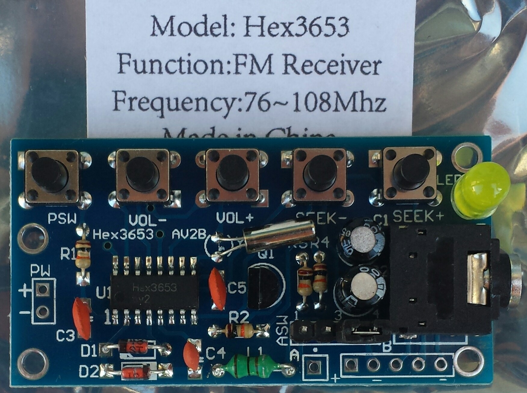
I ordered these kits Several weeks ago and they finally arrived today.  I opened up the package and found several parts rattling around loose in the box.  I found one bag had been cut open, and whoever slit it didn’t tape or staple it closed.

I got to work and assembled one of the kits still sealed in its bag.  It didn’t go as well as I had expected.  There are no instructions with each kit, so I searched for Hex3653 receiver and found an article on eBay that looked like it could help.  It gave the location of several of the components, but the board I had wasn’t the same and used some different parts.  I put in what looked the same then puzzled out what was left.  Later I found goughlui.com, which was much more helpful.

Discrepancies 

The eBay board had only 2 resistors, one 10k and the other 2.2k.  But I had four resistors, all 10k.  I don’t know why mine didn’t have a 2.2k, but having four 10k resistors all the same made the choice very simple.

Antenna

I had to figure out what the four pins and jumper do.  But the above website helped a lot.  The four pins are labeled ASW, which I’m guessing means antenna switch.  One way makes the earphone cord the antenna, the other is a separate wire.  

Performance 

It comes with a two AA cell battery holder, so I soldered it to the PW holes on the left.  I put cells in the holder, plugged in some earbuds, pushed a few pushbuttons and received a station.  I moved the jumper to the left and the station got louder, so I guess that was the one for the headphone cord antenna.  It works okay even though I wasn’t sure if I had put all the parts in their proper places.  Yay!  Now I can assemble some others.

Conclusion

I agree with the conclusion in the goughlui website.  This receiver has a loud pop when turned on, and the volume has too much change between steps.  If you plug this into a powerful stereo system, it could damage speakers or even more.

When the seek buttons are pressed, the seek is muted, but since there is no display, the next station is unknown until the station verbally identfies itself.  A display would help a lot, but it’d be more expensive.

The instructions are nonexistent, but through my previous experience I was able to get through with no problems.  Because of this, and the soldering of the tiny SMD chip, I don’t recommend this for beginners, and hopefully the goughlui.com website and my blog will help future experienced assemblers get through this project without problems.

© RustyBolt.Info/wordpress
CyberChimps