default

2017-07-31 Transistor Radio Repair List Of Problems

2017-07-31 from FB reply by Phillip Grace

The worst is damage from leaking batteries and flood damage. The latter isn’t always apparent at first until you open up the set and find signs of sediment or corrosion. Common problems are of course failed capacitors, physical damage, and bad/failed repair attempts and tampering. Taken care of, transistor radios can be fairly reliable, the transistor devices themselves don’t fail often, but sometimes become noisy or intermittent. A can of freeze spray and a careful touch of a soldering iron applied to devices can ferret out marginal parts. Thermistors used in audio output stages often change value or fail entirely, causing distorted sound when their resistance has lowered, or poor battery life and hot running output transistors when their resistance has appreciably risen.

Speakers can be damaged by water or sunlight over time, finding replacements isn’t as easy as before, especially for odd sizes or ones that have mountings for other devices or fitments like transformers or brackets. For some unknown reason, I find a lot of radios have iron particles stuck around and to voice coils. This metal residue is tough to remove, though using a magnetized pick can slowly pull the debris out. The problem exists after this debris is removed, since the constant tug from the magnet will cause the cone to take a set and be bottomed out in the magnet structure. This can be repaired with small foam blocks between the basket and cone and some humid air and time.

Other oddball issues can be the hidden tubular ceramic caps inside the IF cans. These can fail and leave one scratching their heads knowing all the components measure good otherwise. If there is insufficient range to adjust an IF can, this is a common indication of an uncommon problem.

Volume controls and switches can be a big issue, especially in Panasonic sets. Matsushita used high quality parts in all their electronics, and these controls almost always had silver plated contacts. Depending on the environment where an old Panasonic was kept, the silver can tarnish to a point where the switches and controls will not function, even after judicial use of Deoxit. Use a multimeter to check all switch contacts and pots, and don’t be surprised if there are nearly complete open readings on otherwise closed contacts. I’ve found the Panasonic RF-2200 radios to be especially bad for this. Replacements are unobtanium, with the only solution being to remove and disassemble the switch to clean the contacts individually the last resort.

Variable capacitors are prone to damage, especially the open frame type. Look for bent or rubbing plates, dirt and misalignment. Some varicaps are mounted on insulating grommets, these often fail over time and cause noise, static and inoperative sets.

Some of the green mylar film caps degrade over time, leaving a dusty looking residue on the outside as well as hairline cracks in the plastic coating. These are easy to spot. Check them with an LCR meter if you aren’t sure.

default

2017-07-27 Laptop Charger

from FB reply 2017_07_27 

Richard Robertson

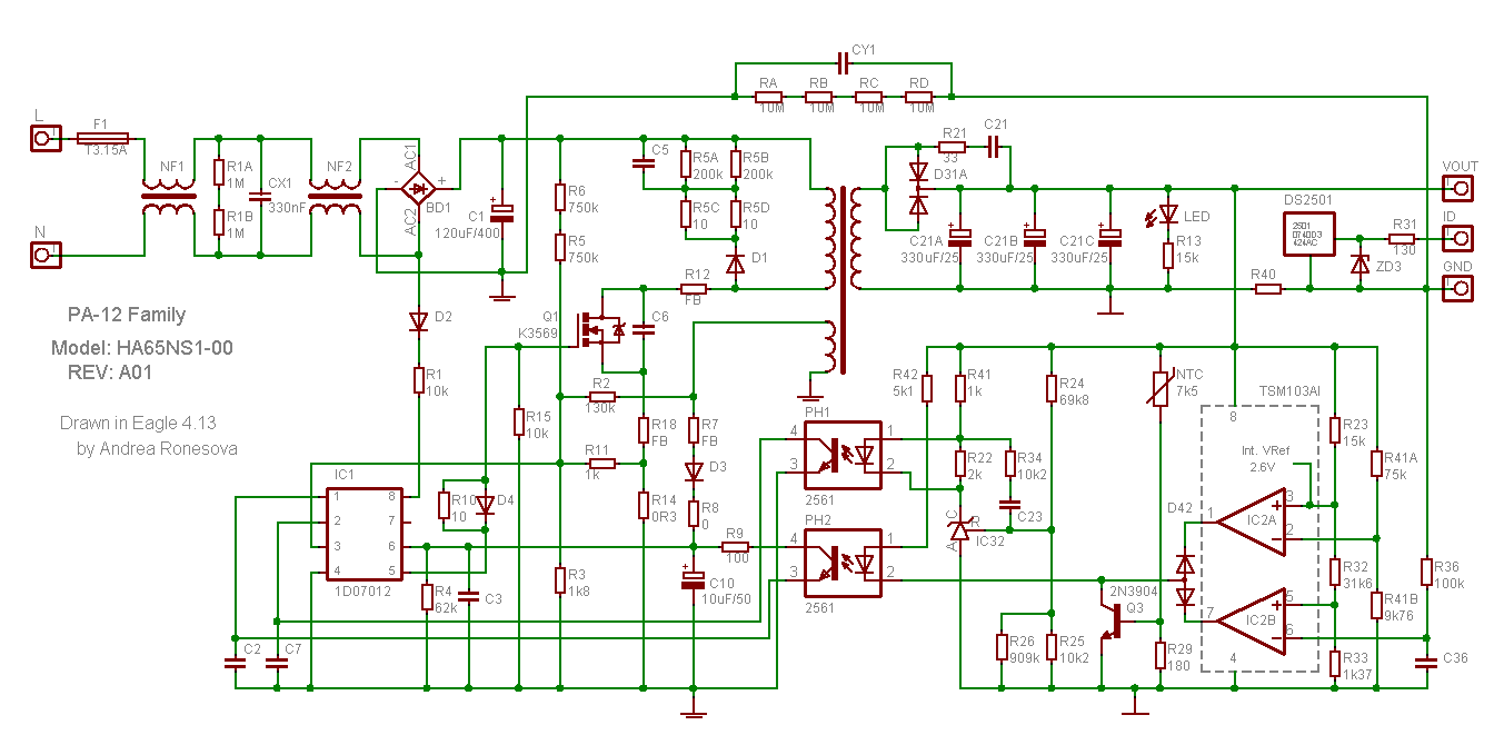
Look at this schematic of a typical laptop charger.  Notice that the left side has the two pins of the power plug.  They are not polarized, and may be inserted into the socket either way.  No pin for ‘ground’ or ‘earth’ is shown.

 Notice that the ‘ground’ or ‘earth’ for the left side of the circuit has two lines, sort of like an equal sign.  Notice that the right side of the circuit uses a sign that’s a single line, like a minus sign.

Notice that at the top, both grounds are connected by four 1 M resistors in series, paralleled by a capacitor CY1.

No matter what is right or wrong with the neutral and other pins of the AC line, it won’t affect this charger, because it doesn’t use the ground or earth pin of the AC line.  Your suggestions to check the electric cable won’t help.

http://320volt.com/wp-content/uploads/2012/01/schema-circuit-dell-pa12-19v-notebook-adapter-smps-1d07012-3-34a.png

default

2017-07-16 tbd

tbd

default

2017-07-13 Don’t Use Your Original Remote Control 

From FB reply

My remotes seem to go bad all the time.  Batteries low or dead, battery juice leaking on the circuit board, broken wires from falling off the table, getting sticky or worn, etc.  I try to minimize the wear and tear on the original remote.  I never use the original remote, I use a cheap universal remote and patch ’em up until they’re beyond hope, then cannibalize the IR LED.  The only time I use the original remote is when I have to access some menu, or add a channel, etc.

default

2017-07-14 Underwater Speaker

From a reply on FB

I built a speaker for a swimming pool.  It was a large can of steel with an audio transformer mounted inside.  The ‘I’ laminations were removed so the ‘E’ laminations could be very close to the end.  I drove it with a 2N3055 on a heatsink.  The secondary winding must have DC flowing to magnetize the laminations.  I used a car battery for power.

I soldered the lid back on the can.  I put clear silicone sealant around the lid where the two wires went through.  It worked okay for awhile but the water leaked in and the steel rusted. 

default

2017-07-15 Appliance Light To Limit Current

Reply to a FB comment about using an incandescent light in series with a repaired equipment to limit the current when it’s first turned on.

You can still get incandescent lights around 40W, but they are called appliance lights.  You can’t expect a LED light to work in a dryer or oven.  Also there are decorative lights that are 60 watts.  All of these are more expensive than a standard incandescent bulb.

Another better option is to use a Variac, Powerstat or autotransformer that will allow you to increase the AC voltage gradually.  The problem with these is they’re heavy and expensive so if the cost doesn’t get you, the shipping will. 

I’ve also thought about connecting several 12VAC transformer secondaries in series with a switch or plug to choose one of various voltages.

default

2017-07-12 It Worked!  Arduino Pro Mini Programmed

This homemade PS is smaller than an ATX PS, but the best thing is it’s quieter, because no fan is runningThis homemade PS is smaller than an ATX PS, but the best thing is it’s quieter, because no fan is running.

default

2017-07-10 Burgess Battery In Old SCR RADAR Set

I took an electronic technician class at Compton College back in ’66, and the teacher gave us an assignment to work on the antique SCR RADAR sitting outside the classroom.  We found that the antenna would rotate but it wouldn’t transmit.  We had the schematics and diagrams for it, so I started looking for some points to measure the voltages.  I found one that caught my eye as being suspicious, it was a dry cell battery that furnished the negative 45V ‘C’ voltage for the grid bias.  So I measured the old Burgess battery in the cabinet, and it was dead.  Even at that time, the old B and C batteries were no longer being used since most portable equipment was “transistorized”.

So I looked around in the schematic for some other source of negative voltage and found a couple hundred volt line, and I put a resistor and a neon light in place of the battery.  The neon light was conducting at about 50 or so volts, sort of like a regulator.  When we powered up the RADAR, it started transmitting!

But ol’ Sal Duarte, the teacher was angry, apparently because we had fixed the broken RADAR set.  He made us shut it off.  Later, at the end of the semester he was very displeased that I had received my FCC Second Class Radiotelephone License.  He threw a tantrum and cursed me for getting the license.  I found out later that others in the class had taken the test and flunked it!  Taking the test was a requirement for the class.

Later I started working for a community college, and found out that Sal Duarte was doing something that was illegal (at the time I was employed).  The state education code prohibits a teacher from teaching more than 1 class at the same time.  Sal would come in at the beginning of our class and give us assignments, then leave to go to the next classroom where he taught electronic assembly class.  So Sal the cheating teacher was gaming the system.  I don’t know if teaching two classes was prohibited at that time, but it was ten years later when I was working at a college.

That wasn’t the only run-in I had with a community college instructor.  But those will have to wait until later.

default

2017-07-09 Microcontroller For Monitoring Solar And Leg Power

I’ve thought about using a DC motor as a generator to charge a super capacitor or battery, using human (leg) power.  If I get an exercise bike, I would like it to do some useful work.  Say, connect the capacitors or battery to a DC to DC converter to make 5V to charge my cellphone.  This might take up to 2 amps, or 10 watts.  This seems to be a reasonable amount of power to generate with my legs for a half hour or more.

But I would like to have the capacitors or battery able to be charged from another source, for example a solar cell or during nighttime from the AC line.  What I would like to have is an ammeter that has multiple inputs, one for my generator, one for the solar panel, one for the AC line, and possibly one spare input for a fourth source, possibly another solar panel or wind turbine.  I might even add a fifth input to allow the battery to charge the capacitor bank. 

I have several stud mount 35 amp Schottky diode rectifiers that I can bolt to a heatsink to ‘wire or’ all of the inputs to the capacitor bank or battery.  That seems to be the easy part.  But I would like to monitor all of the inputs and battery and/or capacitor bank for their voltage and current.  This can be displayed on a few lines of an LCD.

I could do this easily by using a half dozen cheapo DMMs all mounted side by side, with all of them powered by isolated DC to DC converters from any of the sources.  But I think it would be much nicer if all of the Vs and Is were monitored by a microcontroller, and saved to a flash drive periodically for review later.  The uC would be able to automatically switch between the inputs and display them, along with labels like bike or solar.

Also, the uC would save set points for the capacitor or battery and possibly the inputs, and if the charge drops below a certain set point, it would be able to turn on a charging source such as the AC line.  Additional optional functions:  If the charge source isn’t available, it could set off an alarm.  It could also notify remotely by SMS, Bluetooth, etc.  Getting even more capable, it could be accessible online for all the charging information.  

I’m looking for similar projects online.  Hopefully both hardware, and open source software.  I’ve found some similar, just for a single battery and source.  It may just need to add inputs for the additional sources.

Here are some links with related information:

A single board uC

http://www.rlocman.ru/shem/schematics.html?di=107038

default

2017-07-08 Charge Phone from 12V Solar Panel Using SMPS

The guy in FB group asked how to charge his 5VDC phone with a 12V solar panel.  Several others said to use a 7805 V regulator to drop the 12VDC down to 5VDC.  This will do the job, but I told them that the 7805 wastes most of the power as heat, and only a small amount will go to the phone.

The others then gave other ways, but those all wasted most of the solar panel’s power in the regulator.  One of them said instead of using the 7805, use a Zener diode and transistor.  The problem is he doesn’t understand that the solar panel’s power is precious, and it cannot be wasted.  So a very efficient DC to DC converter must be used.

Here is my reply.

“That won’t help.  The problem is the output from the solar panels will not be enough to charge the phone because 2/3 of the solar panel’s power is being wasted by the V regulator.  The only way to get most of the solar panel’s power to charge the phone is to use a SMPS (switch mode power supply).  This converts 85% or more of the 12V to 5V.

A cell phone needs 1 or more amps at 5V to charge.  If the 7805 puts out only 1/2 amp or 2.5 watts.  The phone may use 2.5W or more just to keep the phone service, WiFi and CPU running even when it’s not being used.  With 2.5 W, the phone may never get fully charged.”

Update Jul 10 – Rajesh still doesn’t understand, because he didn’t read my earlier replies.  So here is my reply to him.

“Rajesh Shankhalpura

You are missing the point.  I posted this earlier but you refuse to read it.  If you had, you would understand why you are wrong.

A few more details this time.

The solar panel puts out, for example, 12V at 1/2 amp, or 6 watts.  This can be converted with a switching DC to DC converter to 5 volts at about 1 amp.  That’s just enough to charge the phone.

Instead you say to save money, use a 7805.  So the 12V at 1/2 amp from the solar panel comes into the 7805, and the regulator drops 7 volts, and 5 volts at less than 1/2 amp comes out to the phone.  A small amount of current is used by the 7805. 

5 volts at 0.48 amp is 2.4 watts.  That much current may be used by the phone to keep the phone service, WiFi, Bluetooth and CPU running while it’s trying to charge.  Instead of charging in an hour or so, the phone may take all day to charge, or may never get fully charged.

And this is because your 7805 is wasting more than half of the solar panel’s power as heat!  So now you have saved money with the 7805, and you have to buy a much larger solar panel to fully charge the phone.  You have saved a little and spent much more.

Now that you understand, do you still believe the 7805 is the best choice?”

© RustyBolt.Info/wordpress
CyberChimps