default

2017-06-15 Capacitor Leakage Tester Ideas

I was asking about very old capacitors and their shelf life on FB vintage test equipment group.  The guys tell how good the old capacitor testers are because they have the “magic eye” to check for leakage.

I was thinking that it would be easy to test any capacitor for leakage.  All that’s needed is a 1 meg resistor or maybe 100k for higher leakage.  And a high impedance meter to measure the voltage across the resistor.  Or instead, use a microammeter in series with the capacitor, and a resistor to limit the current.

And then the voltage source, of course.  For a voltage source, I’d use a 230 VAC to 12 VAC transformer, secondary connected to the secondary of a 120 VAC to 12 VAC transformer, with a half wave voltage doubler on the output.  And plug this in to a Variac.  And a high value bleeder resistor on the output.  This would give isolation from the AC line.

If a Variac isn’t available, I could use a high resistance, 2 or more watt potentiometer to tap off the required voltage.  I think that’s how the capacitor testers do it.  The capacitor testers use a magic eye, which doesn’t have the ability to measure the leakage current, it only gives a relative indication of leakage.

I’ll have to look at a schematic of the old capacitor testers to see how they do the leakage test.  The big headache is sorting out the signal paths through the rotary switches used in test equipment.

Update – From FB group, Bob Johansen

“Yes, you can check leakage… The eye tube gives a relative indication, the Heathkit is calibrated for the eye to close at approximately 2 uA when checking paper/ mica caps and 2 mA checking electrolytics, this is considered to be the maximum allowable leakage current for each device.”

So thank you, Bob.

default

2017-06-13 Another Regen Receiver Built – Success!

The previous regenerative receivers I’ve built have been 27 MHz, but they have not been successful, they haven’t received a decent verifiable signal other than the very strong one I made with a dip meter. So this time I would build a regenerative receiver that is much lower frequency, and I chose 10.000 MHz because I can receive the WWV time signal most of the time on this frequency. Also the station is easily recognizable with its constant tones and beeps.

I don’t know where I got this schematic, it was among the hundreds that I have downloaded over the last few months. It looks like it’s European design. I used everything from the left up to R4, but not T2 and its circuitry.
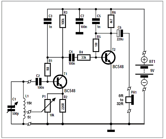
I used a different circuit; instead of a JFET or RF transistor it used a regular BC548 BJT (bipolar junction transistor). I didn’t have a BC548 so I used a BC550C, which is a very high gain version. But the biggest change was the coil. The coil has a tap at 5 turns above common, so the power from the emitter can be fed back to make it regenerate. I used 24 AWG solid enameled magnet wire for the coil. I wound the coil on a wood dowel about 8mm diameter and 40 mm long. I drilled two small holes to hold the wire, using a 55 wire gauge drill bit. I wound 15 turns, twisted the wire to make a tap, then wound 5 more turns. I taped up the coil with black electrical tape. The coil measured a bit more than 2 microhenrys, which calculations showed it needed about 100 pF of capacitance for 10 MHz. I used ElectroDroid on my cellphone to calculate the coil size and turns and the L and C of the resonant circuit.

The emitter resistor is 220 ohms, but a 10k multiturn trimmer pot is in parallel to tap off a small amount of signal and feed it into the tap, to adjust the regeneration .
The collector load resistor was 100k, and the bias resistor between base and collector was 1 megohm. After I got it assembled, I adjusted the regeneration pot, but I got nothing. I measured the collector voltage and found it was only 0.94 volt. The rest of the 9 volts – more than 8 volts – was across the collector load resistor.

I took a break for awhile and thought about what I had learned from the previous regenerative receivers I had built. All of them had been running at very low collector currents, and they seemed to work better after I increased their collector current. So I kept that in mind while I built a 3 transistor audio amplifier for driving the earphone. There is a big problem with running BJTs at low collector voltage and current; they are running at the point where their f<sub>T</sub> is at its lowest and they have a difficult time amplifying radio frequencies. So they don’t want to oscillate in the regenerative mode.

Built Audio Amp

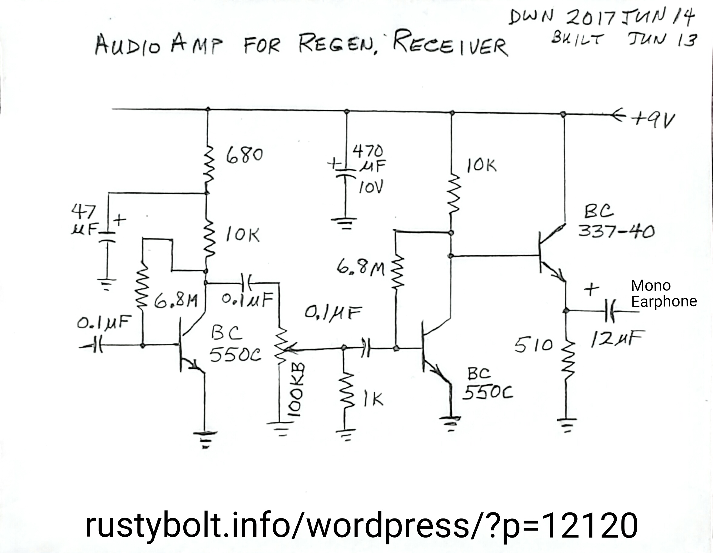
The 3 transistor audio amp is two common emitter stages with the third transistor an emitter follower to give a low impedance output to drive the headphones. Both common emitter stages use BC550Cs and have a 10k collector load resistor. All coupling capacitors are 0.1 uF plastic. The bias resistors between base and collector are both 6.8 Megohms; I calculated the value and it gives about half the 9 volts at the collectors. I put a 100k volume control between the first and second stages. The emitter follower stage uses a BC337-40 (a BC547C is okay) with its base connected to and biased by the collector of the second stage. The collector is connected to +9 volts, and the emitter load resistor is 510 ohms to negative common. The output coupling capacitor is 12 uF, which seems low, but the small values for all the coupling caps are to reduce low frequencies below 300 Hz. To reduce high frequencies, I put a 220 pF from the input to common.

Getting it all together

I used a 3.5mm stereo jack for the output, and a 3 conductor terminal strip for +, – and input. After wiring it up to the power, regen stage and headphones, I had no problems hearing the hum from my finger. I also knew that the regenerative stage was amplifying because the coil was microphonic – I could hear it ring whenever I tapped it or moved it. It was trying to oscillate, so I guessed I was getting close.

I decided to try more collector current for the regen, so I soldered a 22k in parallel with the 100k, which gave 18k total. When I adjusted the regeneration control, the noise increased until the audio sounded muffled, like passing through a low pass filter. I was getting excited! This is the first time I have ever had a regenerative circuit act like those described in literature from as far back as almost a hundred years ago!

I checked the frequency with my dip meter, and when I tuned the dip meter to the receiving frequency, I got a very narrow blip in my headphones. The unmodulated dip meter’s carrier beat with the regenerative oscillations, giving a squeal. This was the first time I have had a regen circuit act right! I was finally convinced that the regenerative circuit could actually receive properly. I added a few feet of wire for an antenna, connected through a 5 pF capacitor to the collector. I tuned the frequency and I heard the “deedle-deedle-deedle” of a teletype transmission. I’ve been chasing after this sensitivity for months, and every time I got close, it would avoid me.

My dip meter was showing that with a 100 pF fixed capacitor and a .5 to 5 pF variable, it was well below 10 MHz. So I unsoldered the 100 and put an 82 pF in. The dip meter showed it was above 10 MHz, so I added a trimmer cap to find out how much capacitance would get it to 10 MHz. With the trimmer almost at its minimum, the dip meter was showing about 10 MHz, so I knew it was going to need just 5 to 10 pFs to get it right on. I removed the trimmer and it measured 11 and a fraction pFs, so I soldered a 10 pF silver mica in. These are very stable over a wide range of temperature, and they’re expensive – more than $2.00 U.S. apiece.

I also knew that the high pitched noise and screechy sound meant I should increase the capacitor from the input to common. The regen’s collector is coupled to the audio input through a .1 uF capacitor in series with a 33k resistor. The resistor is to prevent the audio input from loading the collector. I think it might be better if I used two 15k resistors with capacitors to common to make a low pass filter. for now I increased the 220 pF on the audio input to 2200 pF and it helped.
Right now I need to get it more integrated. The regenerative stage is just a jumble of parts wired point to point. The audio amp is on a piece of perfboard, so it’s okay. I need to put it on a piece of wood or circuit board to make it stable. For now, I’m just making some improvements on this one.

Update Jun 14 – Even with the multiturn trimpot to adjust the regeneration, it’s still very sensitive; it takes only a fraction of a turn to make a big difference. This needs to be changed to a lower value pot, maybe 1k, with the rest of the remaining 9k on the resistors on each end of the pot. But the pot’s resistance needs to be measured, and that can’t be done until it’s removed from the circuit.

The regeneration control and tuning interact slightly, and that should be considered. Right now the tuning capacitor is only 5 pF out of a total of about 100 pF across the coil. There is 82 and 10 pF silver mica caps and the 5 maximum pF tuning capacitor plus a few pFs from the rest of the circuit. I may need to add another 5 pF tuning capacitor.

I noticed that if I get the headphones too close to the regen circuit, the audio will squeal, like feedback from a microphone. I’m not sure if the cause is from the coil being microphonic or if the magnetic field from the headphones is interacting with the coil. The coil is very sensitive to movement or touch.

Update June 15 – I once read an article online that discussed how to change an audio volume control that doesn’t have a logarithmic taper to one that does by adding a resistor to it. Before I did this, when I turned the volume control pot up, it got very loud very quickly, only a fraction of a turn. So I added a 1k resistor from the center wiper lug to the ground lug. Now when I turn the volume control, it has to be turned to about a quarter turn to make it comfortably loud (see schematic). It works much better.

default

2017-06-08 AD Has ADP5090

Ever since I’ve been experimenting with Joule Thiefs I’ve done so with the intention of using the circuit for boosting a low voltage source to power a higher voltage circuit.  So I think this Analog Devices ADP5090 is very useful for doing just that: powering circuits up to 200 mW from very low voltage power source.  This chip requires 0.38 volts to start, but can then draw power from a source of less than a tenth of a volt.  It has MPPT, maximum power point tracking, which matches its load to the power source.  More information about this is right here.

default

2017-06-07 Unibit Is Too Big

I bought a “Unibit” type of tapered drill bit from China, a large one.  It cuts up to 36mm but the shank is 1/2 inch or 13 mm.  I want to put it in a 1/4 inch or 6.5mm chuck.  The only drill I have with a half inch chuck is a big hammer drill.  So I decided to see if I could spin the bit in the hammer drill and file down the shank.  I tried a file, but it just polished the hardened shank.  Same thing happened with a hacksaw blade.  So I got a fine grit diamond coated file, and that started to cut into the shank, but I didn’t see any metal shavings coming off, so I gave up.

I think the shank is too hard to do it with the tools I have.  The shank needs to be in a lathe, and ground down with a grinding wheel.  I need to find someone who has a lathe and can do it for me.  It’s tough getting things to work like you want.

default

2017-06-04 Making A NC Switch Look NO

I’ve been thinking about this for awhile.  Let’s say I have a switch, for example a thermal switch that only has contacts that are NC (normally closed) until a certain temperature is reached.  At that point, it changes to open, interrupting the circuit.  But the input to my controller senses NO (normally open) switch contacts that close when a certain temperature is reached.  So how can I change the switch so that it will work with the controller?

We will assume that there are no other ways to make it work, such as changing the controller or the switch themselves.  And the controller puts a current of 10 milliamps DC through the contacts when they close, and the controller outputs 5 volts DC when contacts are open.  Also, we want to avoid using a circuit that requires external power, such as a relay.

I considered using a single transistor and resistor as an inverter.  The collector and emitter would be connected to the controller with the correct polarity.  The switch would be connected to the emitter and base.  And to turn the transistor on when the switch contacts are open, a resistor must be between the collector and base.  And this resistor must have high resistance, enough so that the controller will not sense it as being closed (the voltage is not high enough), but its resistance must be low enough so that the transistor is turned on with a low voltage.

Let’s say this resistor is 10k.  When the thermal switch is closed, the transistor is not conducting and the 10k resistor will be connected directly across the input of the controller.  With 5 volts across the 10k resistor, there will be 1/2 milliamp flowing.  But the controller would have a current limiting resistor in series with the 5V.  If the current limiting resistor is 5V / 10 mA or 500 ohms, then about 500ohm / .0005A or .25 volt would be dropped across the current limiting resistor, giving us about 4.75 volts at the controller input.

When the thermal switch is open, the 10k will be in series with the base – emitter junction across the input.  So 5V – 0.6V will be across the resistor.  The current would be 0.44 mA.  But this is flowing through the transistor, and turns on the transistor.  If the gain of the transistor is 100, the current flowing would be 44 mA, but obviously the maximum is only 10 mA, so more voltage is dropped across the input’s resistor, and the voltage at the input drops until it reaches equilibrium, at wich time the input will have a low voltage that the input thinks that its switch is closed.

Right now, I’m thinking that it would be easy to just connect a few resistors, a transistor and a switch together and try this.  I’d use a pot for the 10k to see what the optimum value is.

default

2017-06-02 I Built Another Oscillator For AM BCB

I pulled a pill bottle out of my junk box, it had a single layer of solid enameled wire wound on it, and it measured 85 microhenrys.  So I added the transistor, resistors and the capacitors to get it to oscillate at the low end of the AM BCB, around 540 kHz.

The schem is the same as the one here, but with different values.

The circuit is the standard Colpitts with the tap between the two capacitors connected to the emitter and the hot end of the coil/capacitor is connected to the base.  The coil must have a 0.1 uF DC blocking capacitor to prevent the base bias from shunting to negative.  The supply voltage is 9 volts, but it will oscillate at much lower voltages.

I soldered the coil wire to the wrong point, putting the coil across the power supply wires.  I put it on the power supply I made from a wall wart, and I was puzzled why the power supply output went to zero.  I think the short burned out the fuse inside the wall wart, because after I fixed the coil short, the power supply didn’t put out any voltage.  So I have another thing to repair.

The oscillator can be heard strongly when it’s a few feet from the receiver antenna, but I moved it across the room and the signal quickly disappeared into the noise.  I when added a few feet of wire to the emitter to make an antenna, the signal was better, I could barely hear it across the room.

I lengthened the short antenna I had connected to the emitter, to extend the range, but I didn’t hear it on the receiver.  I think the frequency changed due to the longer antenna.

More experimenting with this soon.

default

2017-06-01 How To Disable 5V Regulator?

I’ve been getting PC boards that have all the chips operating at 5 volts, but the input voltage has to be between 7 and 12 volts.  The board has a 5 volt regulator on the board, and often it is a surface mount chip.  But I have dozens of 5 VDC, 1/2 amp AC adapters, which would work just fine for powering these boards.  I can connect a 5 volt adapter to the input, but usually the 5 volt regulator chip has to drop 2 volts, leaving only 3 volts for the circuits.  I would have to connect the 5 volts to the output pin of the regulator chip, but I’m not sure if the regulator will allow this.  I would like to keep the chip, since I might use it later, and the chip might be difficult to obtain, and is not easy to remove or reinstall.

I should disconnect the regulator somehow.  I’ve considered several solutions, but I’m not sure which is the better, or even if they might work.  I’m looking for information, as it seems to me that I’m not the only one who has had this situation to deal with.

I thought one solution is to cut the trace at the output of the regulator chip.  Sometimes there are reasons that can’t be done.

Leave the regulator chip connected and hope it doesn’t eat up power.

Put a rectifier diode in series with the output.  This reduces the output voltage by up to a volt.  So to compensate, a diode would have to be put in series with the ground lead of the regulator.

Other thoughts.  One thought is to ask the board designers to add a point on the trace which is made to be cut open, and has a location on which to solder the 5 volt wire.  This only deals with future PC boards, and the designers may refuse to do it.

default

2017-05-31 Is This a Thermal Fuse?

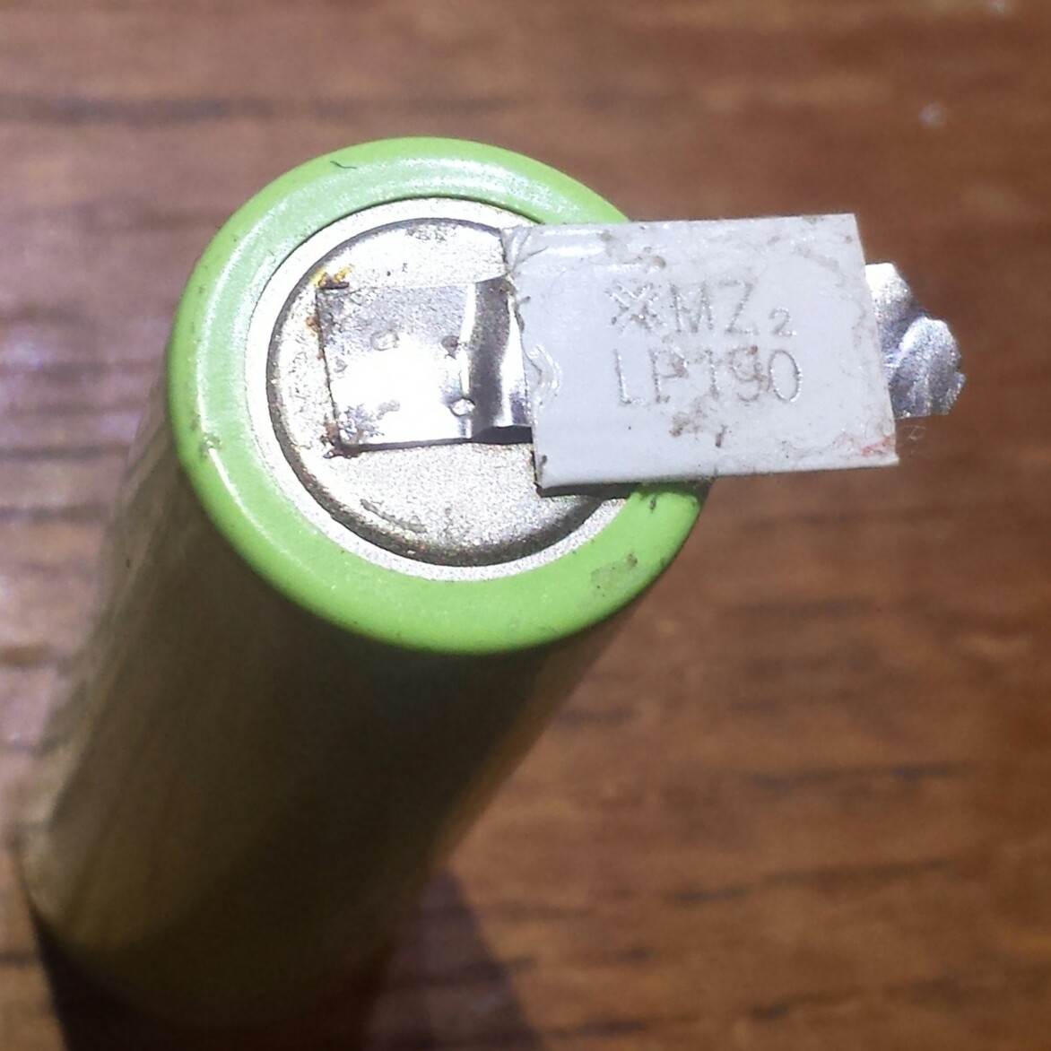
I have a bunch of these Ni-MH battery packs with 5 cells per pack for 6 volts. I want to use them to power 5 volt devices, so I remove one cell.  The metal straps are spot welded between cells, and the metal strip shown in the photo is between cells.  It has two strips of metal that overlap. with labeled heat shrink tube around both strips.  I am thinking this is a thermal fuse, to protect the cells from overheating.  But I can’t remember ever seeing one like this.  Any ideas?


default

2017-05-30 Tick Tock, A Bright Red Clock

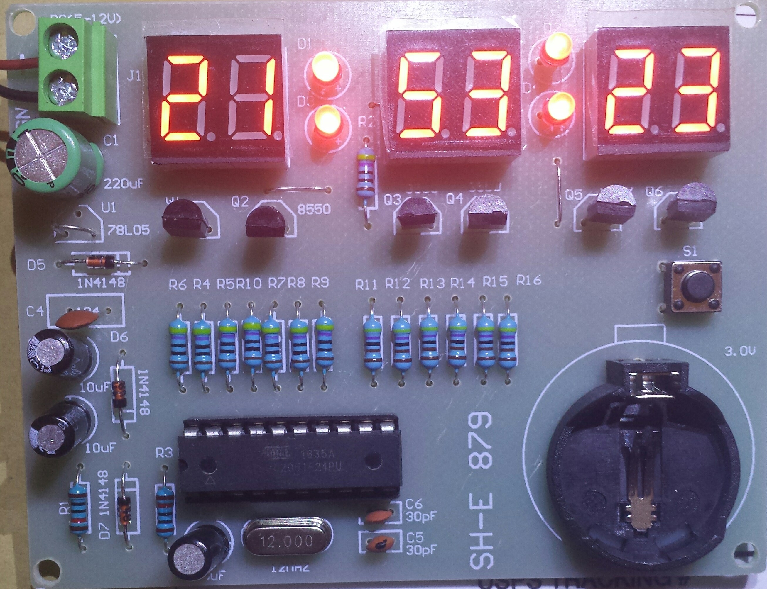
I ordered these clock kits a few weeks ago and they finally arrived today.  I just couldn’t keep my hands off the soldering iron, so I started stuffing the board with components.  I was blindly winging it because the instructions that came with it were in Chinese.  I didn’t have any problems because all the component values were marked on the single sided PC board.  The one thing that might be confusing to the inexperienced assembler was the resistors were 1 percent and have more color bands, but he or she can use a DMM to measure and find their values.  There are only three different values: 470, 4.7k and 10k.

Most of the other parts were polarized and the assembler must take care to put them in correctly.  For me that was not difficult due to the markings on the PC board.  The four red LEDs were 3mm and it was a bit harder to see the markings and stuff them in correctly.  The switch pins didn’t align with the holes so I had to bend them a bit.  When I opened the bag of parts (on both clock kits) the coin cell holder was missing a pin, and it had fallen out into the pile of other parts.  It was a bit of a problem to get it to seat correctly when soldered.

I soldered in the 20 pin IC socket, then I had to bend the Atmel microcontroller chip’s pins to get them to align with the socket pins before it would seat into the socket.  All these minor problems are typical for the assembly of any PC board. 

I didn’t install the 78L05 regulator because I plan on powering these clocks with a 5 volt AC adapter ‘wall wart’.  The board says 5 to 12 volts next to the connector, but the 78L05 needs a few volts difference between input and output to stay in regulation.  That means the input should be at least 7 volts, preferably 8 or 9 volts to be safe.  For now, I put a jumper wire between the input and output of the 78L05.

This kit should make a good project for a kit builder who already has some kit building experience.  There are no surface mounted parts, so soldering is not difficult.  And for just a few dollars, the kit builder can get a project that can be used around the house in many locations.  

Since I couldn’t read the instructions, I had to guess how to press the single button to set the time.  I couldn’t figure out how to change the display from 24 hour to 12 hour format.  It may be the clock has no way to change to the 12 hour format.  It would be nice if I could get the Chinese translated.  I watched a review of a similar but not the same clock on YouTube, and it had three buttons.  It had other functions, might’ve had an alarm.  This clock seems to have had as many features removed as possible to make it cheaper.  One corner they cut is the four colon LEDs.  On the other kit on YouTube the colon LEDs blink every second.  My clock doesn’t blink at all.  And apparently in order to save one resistor, the current for all four colon LEDs in series/parallel goes through a single 470 ohm resistor.  I would have been nice if each colon had its own resistor.  That way, the kit builder could use different color LEDs without having problems getting them all to light.

I’m in the process of assembling the second PCB.  I have to look around to find the bag of coin cells that I got when I bought several red lasers from Electronic Goldmine.  They periodically put the red lasers on sale.  Update: I watched a video on YouTube where the assembler didn’t use the coin cell.  Apparently the coin cell has to power the whole circuit including the display when the power is out (the schematic showed this).  He said that the coin cell can’t power it for long and quickly runs down.  So instead of using a coin cell, he used a few AAA cells.  So what I’ll do is remove the coin cell holder and solder two wires, and put a three AAA cell holder (from a 9 LED flashlight) in its place.

Right now, I need the battery backup more than ever.  Over the last month my other clocks in my house have gone into the reset mode after power failures.  These outages may only last a few seconds, but they are enough to cause my clocks to reset.  For months previously there had been no power outage problems, only recently have there been several short outages.  I’m hoping they will stop and reliability will return.

Here is a review of this clock on Youtube.  He said he paid less than $8.00 for two kits.  He says there is no way to convert the clock to 12 hour format, the clock displays only 24 hour format.  Judging from my experience, I believe he is right.

Update May 31 – I removed the coin cell holder and connected up a four rechargeable NiMH pack.  I changed the 10k resistor across the diode to a 100 ohm, 1 watt resistor.  This allows more current to flow backwards from the power supply into the NiMH pack to keep it ccharged.  The voltage across this resistor is less than 1 diode forward voltage drop, so the current is only about 5 mA.  I forgot to accurately measure the power supply current but it’s less than 100 mA.

default

2017-05-29 M-6013 Capacitor ESR Meter -Not

Several weeks ago I purchased a “M-6013 Capacitor Meter ESR Meter” from a Chinese seller on eBay.  It cost about $27, and I think shipping was 99 cents.  I received it two weeks ago and read all the instructions and tried all the buttons and functions, but I found nothing having the ESR test.

I put the meter back in the box and shipping bag, thinking that I would have to return it for a refund.  It was very clear to me that the seller was falsely advertising the meter’s capabilities, and something must be done to prevent this seller from taking advantage of other customers in the future.

I started an eBay resolution complaint, which sent the message to the seller.  After a few days, they sent a reply saying they were sorry, and offered me $8.00 refund.  I thought it was a fair offer, but the seller would still not be prevented from taking advantage of other customers.  So I replied that I couldn’t use the meter without the ESR capability.  I was hoping that the seller would offer a full refund.  Also, eBay requires that the buyer wait several days until he/she can take the next step if they are not satisfied with the seller’s offer.

The seller then asked for pictures or video to explain the problem.  I thought that the seller was trying to make it more difficult for me to resolve this complaint.  The seller didn’t want to issue the full refund, and the number of days had passed, which now allowed me to escalate the complaint to the next level by sending the message to the eBay mediators.

So I sent the message to mediation, saying that seller advertised the meter as an ESR meter but I couldn’t find anything in the instructions or any function on the meter for ESR.  I said that the seller had asked for pictures, but that I can’t take a picture of something that the meter doesn’t have.  I sent it off, hoping for the best, but expecting more excuses from the seller.

A few days later I received a notification.  It said that the seller had refunded my $27 and shipping, and I was relieved that I had received my money back.  But I am still concerned about how many other buyers will be deceived into buying this meter that doesn’t do what it’s advertised.  How many other customers will start a complaint resolution, and be satisfied with the $8 offer, and be stuck with a meter that can’t do what they bought it for?  How many more meters will the seller sell before the buyers’ complaints make him quit falsely advertising?

I got my money back, but the price I paid was getting the complaint resolved without giving the seller a negative feedback rating.  There was no feedback to warn future customers that the seller was falsely advertising this meter. 

I want to make a comparison between this complaint and the problem I had last month with an Amazon seller.  I bought a drill and an accessory, a chuck and chuck key.  When I received the package, it wasn’t opened, but it was obvious that something had gone through the shipping tape.  I found that the chuck and key had been attached to the display card by zip ties, and the chuck had slipped out of the zip tie and was not in the package.  So I started Amazon’s complaint resolution process.  I went through the menues, and they didn’t have a choice that described the missing part, so I had to choose one for broken.  Also, the description allowed me to type only a few lines of text, not enough to give a comprehensive description.

Then the procedure required me to pack the item in a package for return.  The app issued me a return code, like a bar code, and told me that I had to take the package to a UPS store and show them the code on my cell phone and they would put a sticker on the package and ship it back to Amazon.

I did all this, and in a week or so I received a replacement chuck and key.  But it cost me the money for the package and time to wrap it and take it to UPS.  And it cost Amazon the return shipping costs and processing costs.  But what I liked was that Amazon and seller both got feedback on what the problem was, and how to prevent it in the future.  This feedback is very important because it will help avoid the problem for both the customer and Amazon in the future.

© RustyBolt.Info/wordpress
CyberChimps