


I recently read that Peltier TEGs (thermoelectric generators) are less efficient than conventional electromechanical systems such as turbines/generators. Mayak pointed out that TEGs could be used to generate power by using the difference in temperature between the surface and deep water of the ocean. I found the Wikipedia entry on this, called OTEC, which apparently doesn’t consider TEGs, probably because they’re less efficient than conventional systems. Here is the link to NREL’s OTEC entry. According to them, OTEC has been around for more than a hundred years.

2012-03-21 1V 3A Solar Panel to 7V Converter
 I received the following comment from Mayank and this is the reply to his comment.
Hi Watson,
I have a 1V, 3A solar panel that I want to use to charge 6V SLA battery. I checked some other circuits on the web and they use big torriod cores with 2N3055 transistors. Can I use a mostet like IRF44N to charge the battery? What circuit do you suggest I use? I can hook up the multimeters and check charging current etc.
Regards
Mayank
First off, I went to International Rectifier’s website to find a datasheet for this IRF44N MOSFET, but the search came up null. For our purposes, I’ll assume that this is a low voltage, very high current, logic level MOSFET that needs a gate voltage of 2.4 to 5V to turn fully on.
I received another comment with more info:
thanks for the info. I meant IRFZ44N which has RDS(on) of 17mohm (though will be 1-2 ohm in our operating range). Vgs (2-4V).
Can I not use your MOSFET thief (one using 0702?). If I use fatter wires for primary and 3.7V Li-Ion battery to provide startup voltage, the circuit can provide higher voltage – right?
I am not limited by 1V on solar panels, I just happen to have 2-3 spare solar cells of 3×6″ that I picked from ebay. I can cut them and resolder them in series to get higher voltage at lower current. So I can cut 2 cells to get 2V and 1.5A. Would that help?
Also, how do I decide how many turns I need? Smaller number provides higher frequency so more current but what is the downside of less turns?
Can I keep different number of turns in the secondary? What would be the impact of that?
I am sorry to bombard you with real basic stuff but I do belive your understanding of the JT circuits is rock solid.
The added information is very helpful.
But let’s look at what we have to convert. The solar panel is 1V at 3A, which means it needs a load of 1/3 ohm to supply its rated current. That’s 333 milliohms, which is a very low resistance. If your converter circuit has a tenth of an ohm DC resistance, it will waste almost a third of the power. The circuit will have to have very heavy wire, very heavy copper traces, and very low resistance for the coil.
(As suggested in the comment, it would be very helpful to change the solar cell to 2V at 1.5 amps, because the demands would be much less on the MOSFET and the rest of the circuit.)
Another question we must answer is how much power does the SLA (sealed lead acid) battery need to charge. If we have 3 watts from the solar panel and the converter is 75% efficient, then it will deliver 2.25 watts to the SLA. The SLA will need 7 point some fraction of a volt to charge, depending on the temperature. 2.25 watts divided by 7.2 volts is a little over 300 milliamps. That is going to be a lot less when the sun isn’t very bright.
I have found that it is difficult to get a Joule Thief to draw a supply current of 1 amp at 1.5 volts, so it will be even more difficult to get 3 amps at 1 volt. I’ll discuss how I would do things. Here is one reference where such a low voltage at high current is converted to 5V to run a small computer.
To minimize wiring losses, I would locate this converter at the solar panel. That will allow the higher voltage, lower current to go from the converter to the SLA battery over reasonably sized wire. I won’t need an isolation diode between the solar panel and the converter, because the output of the converter will block any current from the SLA from going backwards when the sun isn’t shining.
Further design decisions. I would start out by making a regular Joule Thief, with a NPN transistor such as the PN2222A or BC337. Instead of the LED, I would use the JT to switch the MOSFET gate on and off. I’ll draw a preliminary schematic of what I would start with to get the DC to DC conversion.
Update Mar 23 – Mayank had a few more questions:
Questions (again):
Transformer: Shall I just wind same number of turns on all 3 coils?
1N5240 Zeners: These are 10V zeners, I understand the logic for 10V so the Vgs doesnt exceed 10V, but why the zeners in both directions?
Output Zeners: You say 5V 1W zeners, 2 of them in series. Is there an advantage of using 2 in series instead of one 10V zener? I suppose that is only to make sure that voltage to the battery doesnt exceed 10V, but wouldnt we be safer with something like a 7or 8V zener?
Thanks again in advance.
Mayank
I would start with a high permeability toroid such as the FT87-75 (20mm outside diameter) (easy to wind) or a Fair-Rite 2673002402 (10mm O.D.), and wind 10 turns for the primary and feedback windings. The secondary to the FET will have to have enough turns to give the +- 10V peak to peak or whatever the voltage is for that particular MOSFET. Also, the number of turns will influence the frequency of the JT, and that may be too low or high for the 22 uH inductor of the MOSFET. This inductor will have to handle a lot of current, and should have heavy wire and a core that will handle the power.
The reason for back-to-back zeners in series is that if you use a single zener, it will limit the peak positive voltage to 10 volts, but the peak negative voltage will be only 0.6 or so volts. There will be a net DC current flow through the secondary winding that could cause the core to saturate. However the primary has a DC current flow, so if the secondary’s net DC current was opposite, it would counteract the primary’s. I think that two zeners are better than 1. Whatever you do, don’t leave them out, the gate voltage could rise to very high levels and damage the FET.
The solar panel will put out 3 watts, and I figure that a bit more than 2 watts will be output, so I used two 1 watt zeners, such as the 1N4733 series. I could have used a single 2, 3, or 5 watt zener. No zener is not an option, because the charger could be powered on without a SLA battery, and that would probably damage the FET.
One rule is you can’t put two zeners in parallel because one will be slightly lower voltage than the other and it will hog the current and overheat. You could use two 1 watt LEDs in series, but their voltage would add up to only 6.6 volts, and the SLA is going to need 7 or more volts to fully charge. You could put two or three 1 amp diodes (1N4002) in series with the LEDs to add a volt or so. Just use a load that doesn’t conduct until the voltage rises well above the battery voltage – you don’t want the load to waste power when the SLA is getting nearly fully charged and the voltage rises to 8 volts. A 9V, 1/2W zener between the base and collector of a TO-220 power transistor would make a 5 or more watt zener. The collector voltage rises to 9.6V, and the zener conducts and turns on the transistor, where most of the power is dissipated.
Just remember that what I’m saying is from what I know and my experiences with the JT. I haven’t put this together yet, so I can’t say how well it will work. You will have to do some experimenting with the values to see what will give you the best results. Also, remember that the solar cell will put out 1V when it’s in full bright sunlight, but when it’s cloudy or at the beginning and end of the day, the voltage will be much lower and so will its output. That’s why I say it will be difficult to get a converter that can boost watts at 1 volt or less. If you can do it, get two volts input and it will help a whole lot.
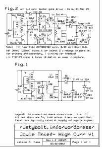
Update Mar 24 – I have looked at a number of circuits that drive a MOSFET and many if not most of them use a two transistor circuit to drive the gate (see Fig.2 in the latest attached schematic). The problem is that the gate of high power and especially high current MOSFETs is relatively large in area, so it has a high gate to source capacitance, thousands of picofarads. In order to switch the MOSFET on and off quickly, it is necessary to charge and discharge this gate capacitance very quickly. If the MOSFET takes too long to turn on or off, power is wasted in the MOSFET and it gets hot and the circuit is inefficient.
The gate of a IRL3302 is 1300 pF typical according to the datasheet, but it might be more than 2000, even though the datasheet doesn’t give a maximum value. The IRL3302 needs only 5 volts to turn its gate fully on.
I added a 1N4148 diode, 10uF cap and 1N5231A 5.1V zener to the JT to rectify, filter and regulate a 5V supply to turn the gate on and off. The third winding might not be necessary if the output from the JT collector is coupled through a capacitor to the gate driver transistor. I added a fuse to the output to protect against battery polarity reversal. It happens! Without the fuse, the zeners and capacitor would be damaged.
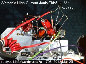
Update Mar 25 – I soldered together the schematic as seen in Fig.2. I posted a pic of the jungle of wiring and parts. I used PN2222A transistors, and the coil with heavy red wire is L1, and is probably more than 10 uH. The output load is two 1 watt white LEDs (half of one can be seen in the far right of the pic). I added a 1/2 ohm resistor in series with the LEDs to measure the output current. Right now with no adjustments, the input current at 1 volt is 1 amp, and the output is 6 volts at 100 milliamps, so it’s about 60 percent efficient. I think that’s pretty good for the first try. The MOSFET is mounted on the heavy heatsink, as is the 10 amp dual Schottky rectifier, and neither one gets warm enough to feel. They just came that way, pulled out of an old PC power supply.
Update Mar 25 evening – I made a few changes to the circuit and got another 20 mA, total 120 mA at 6 volts. Input current was 1.24 amps at 1 volt. I noticed that the voltage across the 5.1V zener was only 4.65 volts, which meant that the JT wasn’t putting out enough current to feed the hungry gate driver transistors with a few mA to spare for the zener. I thought that it might help if I cut back the current from the coil to the bottom gate driver by increasing the resistor from 1k to 2k. I checked and found that the output current increased a small amount. I changed it to 3.3k, and left it at that value. I think that lessened the load on the secondary or driver winding of the coil.
I thought I could get some more current by reducing the number of turns on the big L1 choke seen in the foreground of the picture. I reduced it a turn or two, but I didn’t notice any change in the output current so I put the turns back., Then I decided to take a turn off the JT coil, from 10 turns to 9 turns. That added more milliamps to the output current. I might take another turn or two off later. At the end, the frequency was 76 kHz.
The circuit looks like less than a 1 ohm load to the 1 volt power supply. I haven’t made really strong attempts to minimize the milliohms of resistance in the circuit. I used heavy wire between components and some high current parts, but there are still many other places where the IR losses could be minimized. I still have to squeeze some more power out of the JT to bring the 5 volt supply up to a full 5 volts. Another question is what is the optimum frequency to drive the MOSFET.
Update Apr 2, 2012 – I worked for awhile on trying to get the circuit to put out more current to the LEDs. I was using a PN2222A for the JT transistor, so I changed it to a BC337-40. Strangely, the LED current went down a few mA – it originally was a tad over 100, it went down to 95 millliamps. The reason I changed the transistor was to get more power out of the JT so
I tried swapping the two leads of the winding that drove the gate driver transistors. In the schematic it showed it was connected to a 1k resistor but that resistor is now 3.3k. When I swapped the leads, the LED went dark and the power supply showed it was overcurrent at 3 amps, so I shut it off and switched the leads back to their original positions, and the LED lit back up again. This leads me to conclude that that winding is very polarity sensitive.
I then removed a turn from the primary winding of the JT coil. The LED current went up and the supply current went up. So I removed another turn from the same winding, and the current increased again. The frequency measured 72 kHz and the voltage across the zener was still only 4.7 volts. Right now I measured 110 mA LED current, and 1.3 amps from the supply. It looks like the small increase in LED current is accompanied by a much larger increase in supply current, which means the efficiency is decreasing – not a good sign. One other thing I noticed was when I grabbed the base lead of the gate driver transistor with my long nose pliers, the supply and LED current increased. I’ll have to investigate that further.
More minor tweaks on the evening of Apr 3rd. Only thing notable was I took off another turn from the JT primary winding. The supply current at 1V was 1.45 A, and the LED current was 112 mA.
Update Apr 5 – I checked the supply voltage across the filter capacitor and found that i was only 0.93V, nearly a tenth of a volt was being lost in the resistance of the wiring from the power supply. After I adjusted to compensate, the supply current was 1.6 amps, the LED current was 136 mA with a voltage of 6.1V across the LEDs, and the frequency was 91 kHz.
I thought that the waveform at the MOSFET gate might be rounded a bit by the low pass filter formed by the gate capacitance and the 100 ohm resistor in series with the gate lead. To see if it would help, I put a 47 ohm resistor in parallel with the 100 ohm resistor, and to my surprise the LEDs dimmed noticeably. I removed the resistor, and soldered in a 200 ohm trimpot in place of the 100 ohm resistor. I set it to halfway or about 100 ohms and powered up the circuit. The LED current was about the same, somewhere around 130 mA. I adjusted the trimpot and found that the LEDs were noticeably brighter when I increased the resistance a bit, then got dimmer as I continued to increase the resistance.
This peak was not broad as I had thought it would be, it was a relatively narrow peak, and I was puzzled as to why such a minor resistance change could make such a large difference in the LED current. I powered it off and measured the trimpot at 118 ohms. I removed the trimpot and soldered a 18 ohm resistor in series with the 100 ohm, for a total of 118 ohms. I powered it back up and was pleasantly surprised to find that the supply current had risen to 2.25 amps, the LED current was 144 mA, and the frequency was 103 kHz.
I calculated the efficiency as being about 40 percent, which does not look like it’s all that good, but considering the challenge of having such a low supply voltage, I think it’s about par for the course, so to speak. Think about it: The 1 volt at 2.25 amps is a load resistance on the power supply of less than half an ohm, 0.45 ohms to be more precise. Those small fractions of an ohm in the circuit wiring are probably causing substantial losses, which if eliminated could bring the efficiency up considerably. The circuit should be mounted on a PC board with heavy copper traces and a ground plane to minimize the resistance in the ground. I think that having the components closer together would help minimize those stray resistances, and minimize losses.
Conclusion (?) The circuit design is solid and the circuit is very capable of doing the original objective of converting the 1 volt output of a solar cell to 6 to 8 volts to charge a SLA battery. I think “the devil is in the details,” the small but important resistances in the circuit have to be minimized, and that should help increase output and efficiency.
I’m still pondering why the 100 ohm (changed to 118 ohm) gate parasitic suppression resistor’s value is so sensitive to change. One theory might be that the high current pulses are causing voltage changes in the supply line which is fed back into the Joule Thief and interacting with its operation. I could put a choke in series with the supply line to filter out any feedback. Maybe I’ll try that soon.
Back to experimenting…


2012-03-20 Talkingelectronics Joule Thiefs
On occasion I see others refer to the Joule Thief and flashlight (torch) page of talkingelectronics.com. He has many comments, some good, some not so good, and some that miss the mark. Someone recently mentioned the Circuit B, which is shown in one of the pictures. He talked about increasing the efficiency a lot by adding a capacitor. I found it amusing that he showed the wire on the windings to be 0.095 mm diameter. A millimeter is slightly less than 40 thousandths of an inch (forgive me for not using metric), and a tenth of a millimeter is less than 4 thousandths of an inch, so his wire is even slightly less than that. I’m concerned about using 30 AWG (0.25 mm) wire, which is ten thousandths of an inch, and he’s using wire that’s less than half that diameter! Then he winds 40 and 60 turns on the core, and the resulting DC resistance must be several ohms. The coil for a Joule Thief should have as low a resistance as possible, to minimize the IR losses, and help keep efficiency high. High resistance is bad for a JT. Use heavier wire to keep the resistance well below 1 ohm, and the losses will be much lower.
Poor Designs
He gave two examples of “Poor Circuit Designs”. He said that the first one was a waste of a transistor. I don’t think the transistor was necessary, it has the base shorted to the collector, which turns it into a diode. The designer could have instead raised the 220 ohm resistor to 1000 ohms and it probably would have worked.
The second “poor circuit” is taken from this joulethief.com website, where it is being sold as a kit. This is a common circuit seen often in place of a conventional Joule Thief. The circuit works, but I would have made some changes to parts values, the most important being the 470uH inductor. Small inductors use fine wire and a 470 uH most likely has several ohms DC resistance, which is wasting power. I would have used a 100 uH inductor, which has heavier wire and lower DC resistance, and lower losses. He seemed to criticize the second transistor, which was most likely used to allow the designer to use a simple choke for the coil, with only a single winding, instead of a toroid core with two windings. The second transistor inverts the feedback from the coil, to keep the circuit oscillating. Nowadays a transistor is a few cents and is probably cheaper than the cost of adding the second winding to a coil.
He implied that the second transistor is wasting current and therefore inefficient. The 1k resistor he mentioned has only 0.9V across it when the leftmost transistor is turned off, and only 1.5V when it’s turned on. So somewhere between 0.9 and 1.5 milliwatts of power is being dissipated in this resistor, which is about 1 percent of the total power a typical Joule Thief uses from a 1.5v cell. That’s very minor. I would guess that the conventional 1 transistor JT wastes about the same amount of power in the 1k resistor it uses (but I have never investigated to find out what that power might be). He said that the JT with the feedback winding was more efficient, but with the very fine wire he used, I find that difficult to believe. In my measurements of conventional JTs, I’ve found that they are typically about 40 to 70 percent efficient, with a typical one around 50%. My Supercharged Joule Thief is much more efficient.
Pulsed LED is More Efficient He also makes the statement (I quote) “This proves the fact that LEDs driven with a pulse, are more efficient than being driven by a DC supply.” That doesn’t agree with what I’ve found. In my experiment, I switched a LED between connecting directly to the coil/collector, and to a 1N5817 Schottky diode and filter capacitor to rectify and feed DC to the LED. The circuit and LED were the same circuit, just the switch was added. I measured more current to the LED when it was being fed DC from the diode/capacitor. Read the update at the end and the comment in my blog here. If you want more info about LED efficacy (efficiency) and more about LEDs (and lighting) in general, visit Don Klipstein’s LED web pages.
Transformer The talkingelectronics author goes on to talk about “the transformer.” He then contradicts himself by stating that the Joule Thief coils is not a transformer, but a flyback coil with a feedback winding, and I agree. But why did he call it a transformer to begin with? It isn’t a transformer, because the circuit will function without the feedback winding, as he showed in the second of the “poor designs”.
There are other confusing statements in this section. For instance, he calls it regeneration, but then later says positive feedback. One might call it regenerative or positive feedback, but regeneration is not the correct term. He then says that it “produces a very high voltage..”, which is untrue. If it were true, the circuit would be damaged! The coil stores energy, that if it did not have the LED to dissipate in, would increase the voltage until some other component breaks down. As long as the LED remains connected, the voltage will never be “very high”, the voltage will only rise to the point where the LED conducts. I think it’s confusing to the reader to make these statements.
“Flashing LED” The author continues with a section on a flashing white LED. It uses a second transistor with the collector unconnected, and the emitter to base junction reverse biased so that it zeners or breaks down, causing the LED to flash. If any circuit deserves the term poor design, it is this one. This circuit will never be found in any well designed project because it depends on a transistor’s function that was never meant to be used (the voltage is exceeding the maximum parameters given in the datasheet), and therefore is not controlled or tested when the transistor is manufactured. Thus the transistor cannot be depended on to flash, and this would be especially true at extremes of temperature. Furthermore, if current flows through the emitter to base junction during reverse breakdown, it will permanently damage the transistor, and the current gain will be permanently reduced. If you use the transistor for this purpose it is a good idea to cut off the collector lead so that it cannot be used as a transistor again.
He says it is difficult to visually compare the brightness of LEDs, and I agree. But the point is that one should not use the naked eye to make a brightness comparison of LEDs. I purchased a luxmeter for a reasonable price, I believe it was $40 U.S., and it allows me to make reasonably accurate measurements of the LED brightness. It allows me to make a comparison of different circuits connected to the same LED. If the experimenter thinks that that is too expensive, there is another way to compare LED brightness. Obtain a CdS photocell, and mount it on one end of a small light tight box, and mount the LED in a hole in the other end. Use a cheap DMM to measure the photocell’s resistance when it’s illuminated by one circuit, and compare that to the same LED on the other circuit.
Talkingelectronics certainly does a lot of talking, but I don’t believe it is substantially adding to the understanding of the readers.
2012-03-19 Ancient Dressen Barnes Power Supply
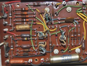 This is a photo of an ancient Dressen Barnes power supply from the 1950s. It uses germanium transistors throughout. Some of them are located on the other side of the board, and the only thing that can be seen are the nuts holding them down and the two holes where the leads pass through. Some others are held to the board with fuse clips, presumably so that they can be removed. The wiring was typical of commercial grade equipment for that day. Each component was soldered into the brass studs that were mounted in rows on the board. When the final inspection was done, the inspector painted a red dot of paint on every solder point to tell that it had been checked. The components could be unsoldered to do a repair but the paint would be removed.
2012-03-18 Invention That Changed The World
 This device is the invention that changed the world. If it had not been invented and developed, you might be speaking German right now. You probably use this every day. What is it? It’s a magnetron. That’s right, a magnetron. In the 1960s, Amana, the company that made refrigerators, came out with a box that sat on your counter and did an amazing thing. They called it the RadaRange. Later companies gave it a generic name, microwave oven, and the magnetron is the heart of the microwave oven.
I highly recommend reading the book, by Robert Buderi. It’s a history of how the magnetron came to be how it was used and how vitally important it was to the war effort..
2012-03-17 Joule Thief in Wikipedia
Have you read the Joule Thief topic in Wikipedia? I think it’s poorly written and lacking in comprehensive information,. It reminds me of the blind men and the elephant: one blind man felt the elephant’s trunk and said the elephant is like a snake; another blind man felt the elephant’s tail and said the elephant is like a rope; another blind man felt the elephant’s ear and said the elephant is like a big leaf, etc. Everyone has a different idea of what should be there. No one has left a good description of the Joule Thief there.
I learned my lesson, though. Someone posted a picture of his version of a Joule Thief: for the coil it used two chokes next to each other, with one choke being the primary winding, the second choke being the feedback winding. The magnetic field from the primary passes through the feedback choke and develops the feedback current to turn on the transistor.
Yes, it works, but it’s mickey mouse because the feedback depends on the location and orientation of the chokes, and how close they are to each other. This is not a typical Joule Thief; I have never seen such a jury-rigged setup previous to this one. I removed the picture and explained my reasons in the discussion tab area.
The person put it back in, and left a note there, too. He apparently thought that everyone should be building Joule Thiefs like this. But I said that it was not a typical Joule Thief and I replaced it with a picture of a conventional Joule Thief. He complained about the blue background color. Picky, picky, picky, so I replaced the picture with a white background.
The lesson I learned is that if you decide to try to improve this Joule Thief topic in Wikipedia with comprehensive information, you may be contradicted by someone else who has decided he is the authority with the god given right to say what is right and wrong and changes what you’ve done.
The only solution I can think of is to start another topic in Wikipedia, with a different title, but dealing with the same subject, which is a low voltage LED driver.
Low Voltage LED Driver
This Low Voltage LED Driver is about a simple one transistor LED driver circuit that allows an experimenter to power a LED from a voltage that is lower than the LED’s forward voltage. Thus a white or blue LED, which requires about 3 volts to light, can be powered from a single 1.5V AA cell or even lower voltages.
History
In the November 1999 issue of Everyday Practical Electronics a circuit was published by Z. Kaparnik that boosted the 1.5V from an AA cell to drive a LED. He gave it the name Joule Thief because it will steal the last remaining Joules of energy from the battery to power the LED. The circuit is not new; it was derived from the circuit known as a blocking oscillator, which had been used since before World War II, in its vacuum tube or thermionic valve form.
Function
The circuit is shown in the pictorial.
The two winding coil that is used is popularly called a transformer, but technically it is a coil, because only the primary winding is needed to do the voltage boosting (there is no transformation); the feedback winding is only used to invert the signal to the transistor’s base so the transistor will continue to oscillate.
Understanding the Principle
In order to understand the principle that is used in the Low Voltage LED Driver, we strip the circuit down to four parts needed to light the LED: a AA cell battery, a white LED, a coil and a push button switch.
We connect the cathode or flat spot of the LED to the negative of the AA cell. and the other lead of the LED to one of the coil leads. We connect the other lead of the coil to the positive of the AA cell. We have a circuit, but because the AA cell is 1.5 volts and the white LED needs 3 volts to conduct current and light, nothing happens and the LED remains dark.
We now connect the pushbutton switch across the LED. Now every time the switch is pressed and released, the LED lights up briefly. When the switch is pressed, the current flows through the coil, and a magnetic field is built up in the coil. When the switch is released, the current stops, the magnetic field collapses and generates a voltage across the switch. But the switch is open, so the voltage rises, and when it gets up to 3 volts, the LED, which is connected across the switch, starts to conduct, and emits light. The magnetic field releases its energy as a brief flash of light from the LED.
The Transistor
If you can press and release the switch fast enough, the flashes of light will be faster than the eye can see, and they will look like a continuous light. So we remove the switch and replace it with the transistor, its emitter connected to the negative of the AA cell and LED, and its collector connected to the coil and LED. The transistor can act as a super fast switch, turning on and off tens of thousands of times each second. But the remaining base lead of the transistor needs a small amount of current to switch the transistor on and off.
2012-03-15 Almost Dead White LED Pic
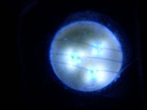 This is a picture of an almost dead white three chip LED. The white phosphor has mostly disappeared, leaving the blue LED chips showing through.
This has thousands of hours on it, but nowhere near the 100,000 hours that they are claiming LEDs last. I have tested a few dozen white LEDs and all of the ones from Hong Kong or China have a huge loss of light output after the first thousand hours or so. Not long thereafter they are worthless for illumination, their light output is less than 1/10 of what it was when they were new.
2012-03-14 Juice Jacking
Want to make a million dollars? Just start selling short USB A female to A male adapters that have only the power pins connected so that only power connects to the phone. Like, why didn’t someone think of this before?
2012-03-13 Scientists Render Fiber Obsolete(!)
Boffins = scientists in UK speak.
http://www.theregister.co.uk/2012/03/14/neutrino_comms_demonstration/
People don’t realize that the Sun generates a huge amount of neutrinos, and every second, 65 billion of the little particles shoot through the area the size of your little fingernail, no matter where you are, because neutrinos go through the earth (and you) like it wasn’t (and you aren’t) even there. Imagine that. No wonder you glow in the dark!
Unfortunately, you have to have a particle generator to do anything with neutrinos, and even then, if you make them, it would seem logical that the huge amount of them coming from the Sun would completely swamp out whatever you were making. So the scientists don’t really have a practical idea or a practical device.
2012-03-12 Slinkys for the Joule Thief Coil
I’ve seen other weird things used for a Joule Thief coil, but this one is really odd. But it works.
