default

2012-03-11 Quantsuff’s Simple Solar Flasher

QS has added two nice little flashers to his web page.  The first, a Simple JT Flasher, uses a regular 1.5V Alkaline cell.  The second uses a rechargeable cell, and recharges it with a solar cell.

I think I would not consider using the solar cell and rechargeable battery on a flasher.   Why?

Well, my thoughts are that the average current drain of the flasher is so ridiculously low – just microamps – that for all practical purposes, the solar cell is just replenishing the rechargeable battery’s normal loss of capacity, which is about 1 percent per day.  My thought is to not bother to use a rechargeable battery on a flasher when a fresh AA cell will last for 2 years when it’s flashing 24/7, and probably double that long when it’s turned off during daylight hours.

I think it’s a waste of a solar cell.  And I’ve found that when I put a solar cell on a project, all of a sudden it’s now dependent on being located in a location where there is bright sunlight during the day.  Or else I have to put a long pair of wires on the cell so that it can be remotely located at the bright light location, and the rest of the circuit located somewhere more convenient, or maybe more appropriate, in a place less inconvenient.  The whole point of a flasher is to attract attention and that doesn’t happen when the ambient light is so high that the flashes can’t be seen.

The other Simple JT Flasher, it would be better I think to turn it off during the daylight hours with a LED and transistor.  My Blue Blinky (its schematic is here but it doesn’t show the LED and transistor that shut it off) has this on the PC boards and it works okay.

Here’s how it would connect in QS’s schematic.  The emitter would be connected to negative.  The LED cathode would be connected to negative and the anode to the base.  The collector would be connected to the junction of the R1 and C1, which takes only a few microamps collector current to pull it to negative.  When the light hits the LED, now used as a sensor, it turns on the transistor and the blinking stops dead.

My Blue Blinky has something like fifty to a hundred milliamps peak battery current draw when it blinks, but the pulse is only on for milliseconds and then off for the rest of the second.  I don’t know what the average current of the Simple JT Flasher is, but it may be less than my Blue Blinky.  It may run for a year or more with a fresh AA cell.  Since the circuit is so much cheaper, it seems logical to seal it including the AA cell in a waterproof container and use it and several others outdoors for holiday decorations, then let them stay until they run down to nothing, then dispose of them.

Update Mar 15, 2012 – Referring to the schematic of QS’s Simple JT Flasher, I built one very similar to this schematic.  I used a coil made from a Fair-Rite 2673002402 toroid with 11 turns bifilar wound, one wire being a 24 AWG solid insulated telephone wire, the other being a 30 AWG enameled wire.  I used a BC338 transistor and white LED.  The resistor between the coil’s feedback winding and transistor’s base was 3.3k just like the schematic.  The resistor between the +1.5V and the coil’s feedback winding was 470k, with a 4.7 uF capacitor in parallel (see schematic).

Okay, my gut feeling was that I’ve built some similar circuits before, and they didn’t flash.  Now, when I first applied power, The LED briefly lit up brightly, then went very dim, and stayed that way.  My gut feeling was confirmed. This circuit is very similar to QS’s, but it doesn’t blink by itself.

I noticed that when I moved the circuit around the very dim LED made the strobe effect where the LED was not a blur, it was a series of flashes of low frequency.  I thought that was a good reason that I should measure the frequency.   However when I clipped the DMM leads onto the emitter and collector leads, the LED started blinking.   Fast, but brightly, though.

I took the leads off and it stopped blinking.  Hmmm.  I took a 330 pF ceramic capacitor and clipped one lead to negative, and touched the other lead to the collector, and it started to blink, but quickly.  I changed to a 2.2 nF (2200 pF) capacitor, and it blinked slowly.  I tried others but I finally settled on 560 pF, which gave a blink of about 1 sec.  Without the capacitor across the LED and transistor, the blinking stops and the LED just glows dimly.

Recapping what I have done, I replicated QS’s circuit, with one added component, a 560 pF capacitor in parallel with the LED and transistor to maintain the flashing.

Back to experimenting…

default

2012-03-10 Core Memory Beads More Than 10 Thousand Dollars

This is a new one for me.  Ten thousand dollars starting bid for a lot of obsolete ferrite core memory beads, made in East Germany.  Maybe someone might be able to afford the shipping, if they live in Germany.  You had better hurry up and bid before someone else gets them.  🙂

default

2012-03-09 joule Thief NOT Self Resonant

I received a Google Alert for a Joule Thief schematic.  They said that it is self resonant, but in order to be self resonant, there must be a tuned circuit with a capacitor and inductor.  It’s really quite simple.  There is no capacitor, there is no tuned circuit, and the circuit is not self resonant.

default

2012-03-08 LM78XX Voltage Regulator Chips

I left a reply in a Yahoo group about power supplies and another commenter left a reply that he used the LM78XX chips often for regulated power supplies, usually without a heatsink.  I would like to relate some of the experiences I’ve had with these wee beasties.

Test Equipment   I worked for a company that built microprocessor based test equipment that used a LM7805 in the power supply.  We would burn them in over the weekend to make sure that if anything failed, it would happen before they left the production line.  We had to send one of the techs to Jamaica where we had several of our boxes  that were failing intermittently.  It just so happened that he was from Jamaica, so he really wanted to go there to see his home.  Anyway, the motherboard had a LM7805 without a heatsink freestanding on the board.  The problem was solved by soldering some short pigtails onto the replacements and bolting the 7805 to the case.  They overheated, apparently because in Jamaica, the sweatshops really are sweatshops, and the equipment and people were working in a hot environment. Also, the AC line voltage was not as well regulated as here in the U.S.

The 7805 chip would heat up, and the internal overtemp protection would shut down, lowering the voltage from 5V down to less than 4.75V which was the absolute minimum  for the processor and other chips.  When the 7805 started to shut down, the voltage drop across it increased – the unregulated input voltage minus 4.75V was more than the unregulated input voltage minus 5V – so the chip would get even hotter.  Just shutting the box off for a few minutes would get it working again, only to have it go bananas later.

Old Modems   I had a few modems, 1200 and 2400 baud, that we were still using until a few years ago.  They would lock up and cause me to have to go out to a site and power them off.  I found out what the problem was.  They were overheating.  The LM7805 regulator would get hot and shut down, and the low voltage would cause the rest of the board to go into an undervoltage confition.  The case was solid plastic with no air circulation to the board inside.  My solution was to drill several holes through the case above (and if needed, below) the 7805, and mount a small piece of aluminum to the 7805 chip.  It added just enough heatsink to drop the chip temperature enough to prevent it from going into thermal shutdown.  Another contributing factor was the AC adapter that came with the modem.  The adapter is rated for 11VAC at 1 amp.  But it actually puts out more like 14 volts AC when the load is less.  So the rectified voltage may be more like 17 or more volts before the regulator.  And that doesn’t include higher voltage when the AC line voltage goes above 120VAC.  That can really add to the heat that the 7805 chip has to dissipate.

Crowbar Effect   Apparently the overtemp shutdown has sort of a crowbar effect.  The chip gets warm and the overtemp starts to shut it down.  The voltage across the chip increases and the chip gets even hotter, and drives the overtemp into further shutdown.  So my experiences with this versatile but somewhat finicky chip is to keep it cool, or else you will be asking for trouble later.  The easiest way to keep it cool is to add a small heatsink. or bolt it to the PC board with a lot of copper under the chip.  Also, sometimes the chip may be slightly out of tolerance and the shutdown temp will be lower than the usual, and cause thermal problems just with that chip, even though it works normally otherwise.  The best thing to do is to replace the LM78XX chip.

I’ve also found that the heat dissipation can be offloaded from the LM78XX chip.  One way is to put a resistor between the unregulated supply and the regulator chip.  The chip still needs a 0.1uF bypass capacitor on the input.  Another way is to put one or more 1N4003 rectifiers in series with the supply; each rectifier will drop about 0.8V.   Three or four in series will offload a watt or more, and that may be enough to keep the LM78XX from going into overtemp.  but the power is till being dissipated in the case, so the case will not be any cooler.  It may be necessary to put a heatsink on the chip or some other way to get rid of the heat.

Newer Equipment   Nowadays, hardly any new piece of equipment uses these LM78XX linear regulator chips.  The newer stuff uses a switching regulator that dissipates far less power, and is much ‘greener’ – Energy Star rated.

default

2012-03-07 Optical Device is More Than 100% Efficient (!!)

Quantsuff sent me an email with this link, a for real COP > unity device.   Well, I’m not so sure.  You see, if it has to be used with the external heat contributing to the light output, then it really isn’t greater than unity, it’s just drawing energy from an external source.  TANSTAAFL.

I had this dream where there were students who rigged up a very large amount of potatoes with coins stuck into them to make batteries and wired them up to power a whole town.  After awhile rotten potatoes became the number one problem.  Could this cause a shortage of French fries?  Watch out, McDonalds!

Believe me, the only way to go is to put solar photovoltaic arrays on top of buildings and feed the resulting electricity back into the grid where it can be used during the daytime.

Thanks to Quantsuff for the inspiration.  Though I’m not sure 70 picowatts of light is of much use in everyday life.

default

2012-03-06 LED “JT” Works With BC337 Transistor Backwards!

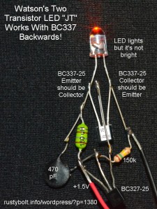
I looked at the photo in the Yahoo Group Joule Thief, and saw that it was working, but then I noticed that the BC337 transistor looked like it was backwards.  I had to look at it again to make sure that I was seeing it correctly.  Yup, it looked like it was in backwards, but the LED was lit up.  I thought that it shouldn’t be working, so I decided to replicate the circuit and see if my replica would also work.

I used the same two transistors, the same capacitor and resistor, and the same color amber LED.  I couldn’t find a 120 microhenry ‘green blob’ choke so I used a 180 uH instead.  I soldered it together so the parts were roughly in the same location as in the photo, see my attached pic.  I connected it up, and it worked!  But the LED wasn’t bright, and it was drawing very little current from the supply, only 5 milliamps.

I unsoldered the BC337 and soldered it back in the correct way.  This time, at 1.5V, the supply current was 10 mA, still not enough but twice as much as when it was backwards.  The frequency was 18kHz and the LED was much brighter.  I put another 150k resistor in parallel with the original, and the LED got brighter and the supply current went up.  I think for my replica, an better choice for this resistor would be about 47k.

I thought about how the transistor was working backwards.  When the emitter junction is used as the collector, it is reverse biased.  The emitter to base junction has a breakdown voltage of only 5 volts.  But since the supply voltage is only 1.5V, and the LED prevents the collector voltage from going over 5V, there is no problem with a rating of only 5V maximum collector voltage.  So the circuit will work, however the transistor will have very low current gain because it was not made to operate in this mode.  That’s the reason why the LED was dim.

Back to experimenting…

default

2012-03-05 Kickstart this Magnic Light Invention, Please!

I found an invention that I think is worthy of investment. The guy has a really amazing invention, and needs the money to get started.  And it has to do with LEDs – cool!  Actually, you don’t have to invest much, a dollar or more, or buy the T-shirt as I did, or more if you can, or need an amazing magneto light for your bike.  But it has to be done by March 19, 2012.

I would never have thought of using eddy currents to do the generating.  See the video for a brief explanation. There are NO moving parts, no rotor, no shaft, no bearings or bushings, all of which waste energy due to friction.  I’m speculating, but if this could be scaled up to work in other places such as autos, windmills, or electricity generating plants, it could dramatically increase their efficiency.  It should have been invented decades ago.  Please help this guy, he’s so close to his goal.

Update Mar 8 – I received an email that said that they have surpassed their goal of $50,000 so anything over this is icing on the cake.  😉

default

2012-03-04 ATCA, NOCCC meetings

The Antique Telephone Collectors Association annual show took place yesterday at Placentia Presbyterian Church, Placentia CA.  I got a few good pics of the stuff.  Those blue and white roundish “Public Telephone” signs are selling for $500 to $1000 apiece.  Just think of all the money one could make if they had collected a bunch of those long ago.

Today is the monthly meeting of NOCCC, North Orange County Computer Club.  The usual, I would guess, but check the link I just gave for anything new.  Next month, April, will be the 36th anniversary of NOCCC, so we will probably get a free birthday cake for lunch.

Well, there was nothing exciting at the NOCCC meeting.  Larry Klees went over to Bruxie and bought a Bruxieburger and showed it to us before he devoured it.

default

2012-03-03 Watson’s 3 LED Flashlight

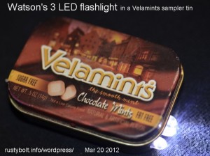
In 2000 and 2001 the pirate manipulators the likes of Enron drove So Cal Edison and the other electric companies in California to the edge of bankruptcy and caused the electricity shortage, and along with that threats of rolling blackouts.  I was concerned about being stuck in some elevator without a flashlight, and since LED flashlights were not yet available, I started building LED flashlights with three AA cells and 6 or more LEDs inside of Altoids tins.  A few years later I got hold of several Velamints sampler tins that were just  big enough to get a single AA cell holder and small circuit board with three LEDs inside.

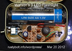
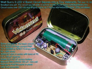
The Flashlight   I built several of these and have them strategically placed around the house for quick use to see stuff inside drawers, etc.  I made a hole for a submini SPST switch and three holes for the Nichia NSPW500BS LEDs, which are connected in parallel.  I built the two transistor circuit on a small piece of perfboard and mounted it and the battery holder inside with hot glue.

Circuit Details –  (I found an older pic with more info – see below)  I used a two transistor circuit with the 2SD965 high current transistor for the LED driver.  The black choke with “104” on top is the 100 microhenry choke that boosts the voltage.  I bought them for a dollar apiece from Mouser.com – I had not yet started winding my own toroids by then.  The other transistor is a BC327-25.  There is a 100 pF ceramic disk capacitor to couple the output back to the base of the first transistor, a 100k to minus for the base bias to the first transistor, and 47 ohm and 820 ohm resistors.  At that time, the white LEDs were selling for $4.00 to $5.00 apiece at Radio Shack, so I soon ordered a hundred from Nichia at half that price, $2.00, and later a bit cheaper.

During the early 2000s the only white LEDs available were the 5mm that could handle 1/10 of a watt.  To make a bright flashlight, it took a half dozen or more to get a decent beam of light.  During the mid to late 2000s, the prices of LEDs began to drop, and the makers came out with the higher power white LEDs, the 10mm and strawhat types that could handle a half watt or a watt or more.  Flashlight makers started to make decent little flashlights that used a single half watt or 1 watt white LED with a reflector, and a circuit to boost the 1.5 volts to that needed for the LED.  I don’t carry my homemade flashlights any more, I carry a Fenix LD01 0n my keychain, and it puts out an unbelievable amount of light for its small size.

Back to experimenting…

default

2012-03-02 The Country Is Broken, Gabe Watson “Honeymoon Killer”


The country is broken because the system is fixed.

Seen on a T-shirt of Occupy Wall Street protester on Bill Moyers,7 PM, Fri, Mar 2, 2012.
Second topic: Gabe Watson the Honeymoon Killer, was featured on “20/20” (ABC, 10 PM Fri, Mar 2, 2012).  The newlywed couple went on their honeymoon to Australia and went on a scuba diving expedition.  At 50 feet down, she began to sink deeper, and Gabe failed to help her.  The Australian legal system has an obscure law, negligent manslaughter, to which he pleaded guilty. and served 18 months in prison.

He got out of prison and came back to the U.S., where the state of Alabama arrested him for manslaughter.  The prosecutor claimed the motive was to collect her life insurance.  It so happened that the beneficiary of the life insurance was not Gabe, and it was for only $35,000 dollars.  Gabe had spent $10,000 on the diving honeymoon, and $3,500 for her wedding ring.

The judge dismissed the case for lack of evidence.  More can be found about Watson here or just do a search for honeymoon killer.

I cannot understand how this came to trial here in the U.S.  First off, he was convicted and served his sentence in Australia, so retrying him in the U.S. is a violation of the Fifth Amendment prohibition against being tried twice for the same crime.  Second, the crime occurred in Australia, so the U.S. legal system does  not have jurisdiction over the crime.

But the newsmedia has had a field day with this one, at the expense of Gabe Watson.  It seems to me that he will never be free of the stigma of something that he claimed was an accident.

© RustyBolt.Info/wordpress
CyberChimps