


 I’ve blogged this project more than once in the past, (and here too), but I didn’t follow through with the circuit completed and installed in a DMM. Well, I finally got my act together and on the road, and finished the first working 1.5V to 9V DMM power supply.
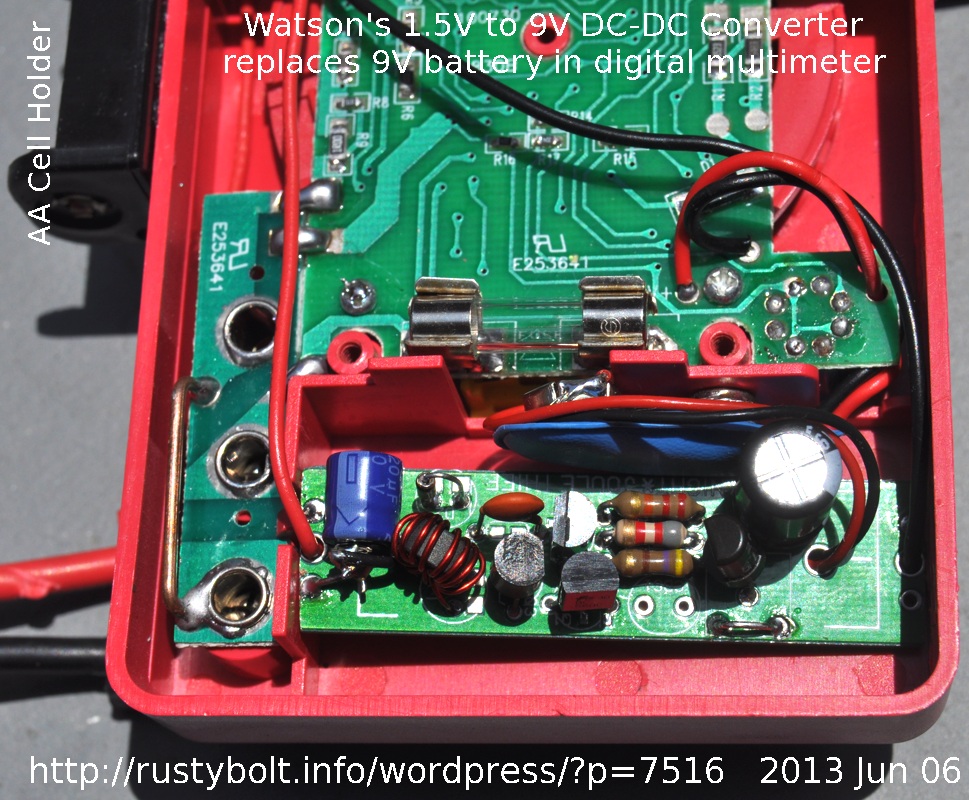
I thought about it and concluded that since I have a bazillion Joule Thiefs from previous experiments, I could use one of them to be the basis for this DC to DC converter. After considering various circuits, I came to the conclusion that I could use Aki Sadoi’s “Night Joule Thief” circuit for the project, after making some modifications to it. Information about the PC board is in the Instructable and on his website. I purchased the bare PC board. The parts values I used are shown in the schematic. I did not have to drill any holes in the PC board. Refer to the attached photo (click on it more than once to enlarge). I had to sand down the ends of the PC board to get it to fit into the battery compartment.
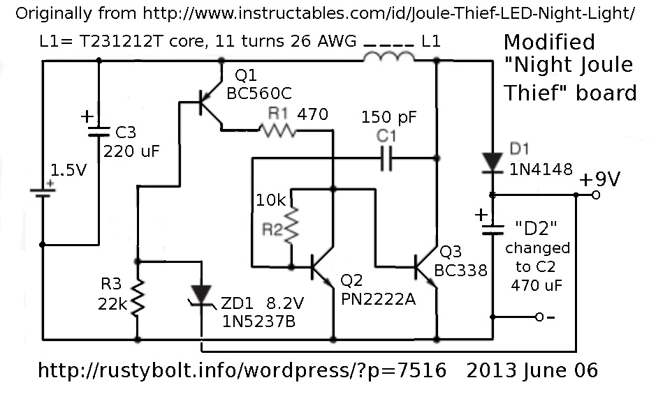 This circuit is ideal for the DC-DC converter because it has a third transistor that is used for control of the converter. When the voltage gets to 9V, the Zener conducts and turns this transistor off, and the converter cuts back on battery current, so when there is no load, it draws only about 5 mA from the single 1.5V cell. As the load increases, the 9V drops, the zener stops conducting and this transistor turns on and supplies more current to the converter. At maximum load, which is about 5 or 6 mA at 8.5V, the converter is drawing about 70 mA from the battery.
The DMM draws only a few mA on most ranges, so the battery only has to deliver about 10 or 20 mA. When the DMM is set to the resistance measuring ranges, especially the 200 ohms range, the 9V current goes up to 5 or so mA, and the battery has to deliver about 60 to 70 mA. The AA cell I’m using should last a long time, but the current is low enough that a AAA cell will work. I did not include an On/Off switch in the battery lead, because I plan on removing the cell or I will put a small piece of plastic between the cell and the contact when I’m not using it. A small switch is recommended.
I replaced the ‘upper’ LED with a 1N4148 diode which rectifies the pulses, and the second LED instead is a 470 uF capacitor (black one on the right) that filters out the high frequency pulses. I show an 8.2V zener in the schematic, but I chose to use an old transistor instead. The emitter to base junction on most silicon transistors breaks down or zeners at about 7 to 9V, so it can be used as a zener. I had to try a few transistors to find one that broke down at about 8.4V, but since this can damage the junction, I clipped the collector lead off so that it could not be used as a transistor in the future. I have not tried the 8.2V zener. I did try a 6.8V zener in series with a red LED, which gave an output voltage of about 8.5V, a little on the low side but it worked okay with the meter.
The CdS photocell and VR1 are not needed, and were left out. I put a 220 uF capacitor across the battery (blue one on the left). I show a 10k for R2, but I used 8.2k. This resistor has to be low enough to turn Q2 fully on, so that it is fully saturated and keeps its collector voltage well below the 0.6V that will turn on Q3. Q3 could also be a BC337-25. Other transistors may work for Q3, but it has to have very low saturation voltage at high currents. The BC547 and 2N3904 are not good choices for Q3.
The T231212T core was from Surplus Sales, and cost about 25 cents U.S. The core can be larger, but I chose a small one so it would easily fit into the battery compartment. I wound 11 turns on it, but the number is not critical, 10 or so will work okay. 28 AWG (0.3 mm) wire should work okay, too. Just try out your own hand wound coil. If yours doesn’t seem to put out enough current, remove some turns and try it again, to see if it helps increase the current.
You don’t have to wind your own core; you can use a 100 uH choke instead. The toroid has less electromagnetic radiation than a choke. I didn’t experience any weirdness in the meter, but it could happen if the meter picks up interference from the converter. That’s why I used the large 470 uF filter capacitor. If interference is a problem, it may require that the 9V is filtered with some RF chokes, and/or use of an EMI suppressor sleeve. With the parts as shown in the schematic, I measured the frequency at about 150 kHz, but it varies somewhat with the DMM current.
I drilled two holes through the case and ran the battery holder wires through them, then I glued the holder to the case with clear silicone glue. Hot glue might work okay, too.
I have a few more bare Night JT PC boards, and I’m going to get another one or two working, maybe this weekend (June 8-9). I think I’ll try to use a 100 uH choke instead of a toroid. I’m just trying to get a feel for what to do and what not to do. After a few builds, I usually find out if and where any weirdness might be. Then I can make modifications to get a circuit that is stable and works good.
Addendum – One other point about the Night JT circuit is that it uses a NPN for Q2. This has an advantage – or a disadvantage depending on how you look at it – that it limits the maximum current that can be drawn by the base of Q3. I think this is why the circuit would not go above about 70 mA when the load current is at maximum. In the case of the LED, it would limit the maximum LED current and brightness, But in this case, it prevents the circuit from drawing excessive current from the battery.
If this feature was sacrificed, this Q2 transistor and R2 could be eliminated and the bottom lead of R1 connected directly to the base of Q3. Then C1 would be connected to the base of Q1. This is the typical two transistor “JT” circuit seen in many places on the ‘Net. The R3 10k resistor would then be split into two resistors and the zener diode connected to the ‘center’ or middle leads of these two resistors. I have yet to try this configuration, though.
Back to experimenting…


Neat, but I would still like to run DMM from 120ac household line to cut down on buying batteries, one day.
The problem is how do you isolate the meter from the AC line, without compromising the safety. If the meter probes connect to a high voltage, greater than the meter is supposed to handle, and the meter gets zapped internally, the high voltage might then cause a leak between the HV and AC line and the 120VAC will then really cause some damage, or could even be lethal. When the meter is self-contained with nothing but the battery for power, the HV would have to penetrate the case of the meter, which is much more difficult than if it had to go back into the AC power line.
Then there is the possibility that the AC line power could disturb the equipment that you’re measuring. This is especially troublesome with audio circuits, where connecting a meter could introduce AC hum into the sensitive circuits. So battery power looks much more attractive when you consider all the problems possible with the AC power line.
One would use an isolation transformer or a small switching supply. I fryed a good meter a while ago it had a 9v battery in it meter set to 1000ac but unknown transformer under test was 1400vac there was a flash and a puff of smoke and that was it for the meter.
It brings a smile to my face. I’m ashamed to admit I’ve fried a meter before, wiggle stick type. Live and learn, I guess. In that case, I managed to replace the burned out shunt resistor (it fried when I left the meter on current range and I connected it to a power supply).
One thing that’s extremely important is the safety of the user. When something like a meter might be used in an environment such as outside where it and the user might get wet, there is the possibility of getting shocked – even killed – from leakage from the test leads and meter. That’s why over the years the test leads have had to met tougher regulations. The cheap meters come with test leads that have special banana plugs with a lot of plastic around them, just to prevent leakage from the plugs. Safety is the *primary* concern, by law.
This is why I would not feel safe if I was using the meter that was meant to be powered by a battery, not meant to be powered by AC, and had been modified to be powered by AC power.
My first modified meter has a battery that is mounted externally, and violates the insulation of the case. I can avoid a shock hazard by setting the meter on the bench and not touching it while I’m poking around with the test leads. One thing I was taught when I worked on million watt RADARs was that you only have one life, so don’t put it at risk. You can’t come back to life after you have been electrocuted. 🙂
I think everyone has or will fry a meter at least once. but for measuring resistors, caps., etc.out of circuit I think would be fine to have the meter powered by a switching supply. soon I will try this by powering the meter with computer power supply with 9v regulator.
The problem with PC power supplies is they typically require a minimum current load. If the current is less than the minimum then the voltage usually goes up above the 5V or 12V, and then the overvoltage circuit kicks in to protect the (nonexistent) mother board. So the power supply just switches on and off or shuts down completely. If you put a 5 ohm resistor on the 5V, the 1 amp current may be enough to keep it from going into the overvoltage protection mode. It may even take more than 1 amp load. Sometimes you can read on the label (or website) what the min and max currents are for the supply. But remember that 5V at 1 amp is five watts, so the resistor should be rated at more than 5 watts.
Been using 6-8 ohm resistor, depends on the power supply some are very particular, 20 watts or more. What works well and does not heat up are 2 elements from a small toaster oven in parrallel. On the one on the bench has a 30w 6 ohm mounted over the fan, been abusing it for 2 years no problems yet. Can not buy the cheap DT830D multi meter here any more they got recalled by the goverment as not safe.Had bought some for $5.00 each with battery and worked well, so if I fry one no big loss.
Yeah, when people think of a load resistor, they forget to consider an auto light bulb or a heater element like yours. But with the trend towards going green nowadays, it’s not really green to waste power. I’ve been checking the goodwill stores and thrift shops for regulated DC adapters from printers, laptops, PC speaker systems, etc. These adapters put out a regulated 5V, 12V, 16V or even 24 volts. They use very little current when they have no load, so they can be left plugged in. I got some from MPJA.com, which usually has a good selection of adapters. Some are only a few dollars, but they can be heavy, which may make shipping costs high. Another way is to get those adjustable switching power supply modules from eBay. They are dirt cheap, only a few dollars U.S.
found this (no batteries)
http://cp.literature.agilent.com/litweb/pdf/5990-3971EN.pdf
Not cheap but can be done.
I got my HP (Agilent) bench multimeter from an eBay seller, for $75 U.S., but HP stuff is usually high priced or has a problem that the seller is “unaware of” (yeah, right). Usually it’s easy to fix, like the electrolytic caps are bad. Replace a few caps and the supply is then usable. Then you have to do a dispute resolution with eBay to get a refund (unless it’s ‘as-is’). But I have HP power supplies that I got for fifty dollars including shipping.
I try to make everything from things others throw away, pc power supply gives you high current and is not on longer than you need. Have a ton of the DC adapters all free. Read that some Fluke meters come with a DC adapter for power also. Nice deal on the HP multi meter, good that we know how to fix things, they know something is wrong. I got 2 lcd TVs that didn’t work properly and found the same 2capacitors no good, now I have 2 digital lcd TVs free and the replacement caps came from a dicarded pc monitor. Was thinking about this supply http://uzzors2k.4hv.org/index.php?page=benchsmps1 but not sure about running it on 120vac than 220vac, if the transformer needs to be altered.
That power supply can put out over 750 watts!! You had better make sure that the GDT and power transf are well insulated because that’s all you have to keep the AC line voltage from going into your output. The existing schematic uses a full wave bridge rectifier, so what you do is add another capacitor and make it a voltage doubler, and you will then have the 230VAC. Here are some schematics.
http://electriciantraining.tpub.com/14179/css/14179_217.htm
One thing I noticed was the three capacitors that pass the high current of the rectified and filtered AC line. These are 3 or 3.3 uF at 250 V. They are shown as two curved lines, like this )(, not two straight lines. This means they are special low loss or low ESR capacitors. The bridge rectifier is 8 amps, so these capacitors are passing several amps at hundreds of volts. My assumption is the high current will cause normal capacitors to get hot and fail, and since the power is so high, the failure would be with spectacular results. This needs to have good fast acting fuses to protect against shock and fire hazards.
I agree, will wind the transformer myself so I know it’s insulated right. The creator suggested to lower the primary turns by about 1/2. Voltage doubler was my first thought too. Will have to do some searching for the capacitors. Always seem to be missing 1 part. Is there a way to send you a picture ?
My yahoo email address is acmefixer. I would suggest you check the Tesla Coil makers forums and websites. They use special capacitors to handle the very high powers that a TC requires. You may have to get smaller caps and put them in parallel. Also, you may be able to get the capacitors from an old PC power supply.
One thing that you may have to do if you full wave rectify the 120VAC is not only reduce the transformer turns, but also increase the capacitors. The problem is that if you cut the voltage at the filter capacitor in half, you have to double the current to keep the same amount of power. This means your capacitors and transformer winding have to be 1/4 (yes, one quarter) the impedance. That means four times the capacitance. Something like 12 microfarads instead of 3.