


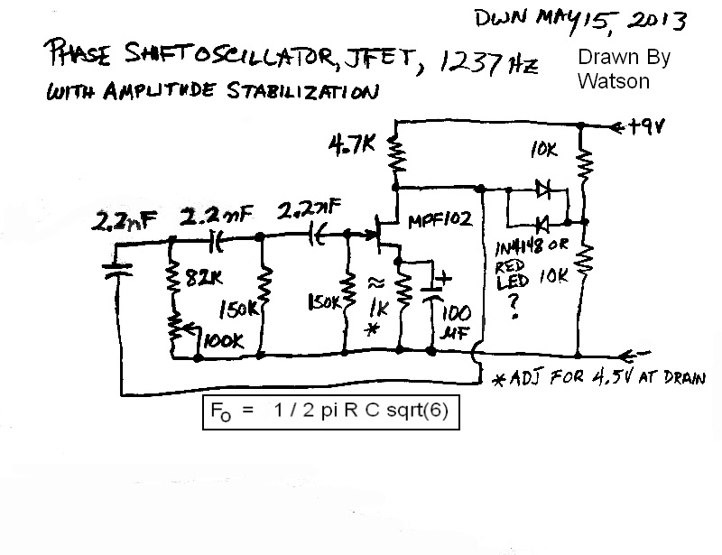
 Drawn May 14, 2013. I plan on building it soon. I think it would be better to replace the 82k with a 130k and use a smaller value pot, maybe 25k. I may have to use some 1% precision resistors and capacitors to get the frequency to be stable over a temperature range and supply voltage range. The idea is to be able to receive this with the superregenerative receiver that I blogged earlier, and use the signal to close a relay to tell me the garage door is open. The receiver will have a band pass filter to prevent false triggering by noisy interference. I got the formula out of a website, but I think the formula should read Fo = 1 / (2 * Pi * R * C * sqrt(6)), in other words the 1 should be divided by the whole expression.

2013-05-15 Phase Shift Oscillator, JFET, Stabilized


2013-05-14 Raspberry Pi
Late last week I received my order from Element 14. I got three Raspberry Pi boards and two Adafruit clear cases, with shipping and tax the total came 158 dollars U.S. and change. I already had my own keyboard, mouse, 5V AC adapter with a micro USB plug on it, a HDMI cable, and a 4 MB SD-HC card. These are what are needed according to their Getting Started Guide (PDF). I also had to download one of a few different operating systems, so I chose Raspbian. There are a few other choices.
The board does not come with the HDMI cable, so that cost about ten dollars. But it can get much more expensive if you buy one from a retail store. The other alternative is to use the Composite out RCA jack, but I don’t think it’s as high a resolution as the HDMI cable (I haven’t tried it yet). The HDMI cable supports audio if the monitor has speakers.
I took it to work and the guys helped me do some adds to the basic package. One thing I really wanted to do was to get Kicad running. This is a suite of schematic drawing and PC board making software, and I wanted to start using it to get away from being locked in to using the ExpressPCB service that I had been using last year (see note at end). The basic GUI comes with Midori web browser, and several other programs. I’ve been using Puppy Linux for more than a year and I’m getting familiar with this Linux environment.
Note: More about Kicad – ExpressPCB allows you to design a PC board and submit it to their service. I found that Futurlec.com will also accept PCB designs done in ExpressPCB. I have not tried their service but I’ve heard positive stuff from others about it. Most other PC board makers only accept Gerber files, and that is what Kicad creates. Thus submitting Gerber files frees you from the restrictions imposed by ExpressPCB, and allows one to shop around for a decent PC board price and enable you to choose extras and add-ons if you need them.
With ExpressPCB and ExpressSCH I found that the included library was inadequate and I had to make many of my custom components, which wasn’t difficult, but it was tedious and time consuming. My guess is that the same thing will happen with the Kicad package, since you don’t get much for free. I suppose I could pay hundreds of dollars and get a more advanced package, but then I don’t know if I’ll get much more, since I’ve never done it. I guess I’ll be updating this or a future blog when I find out more.
Update May 21 – At work we plugged the R Pi into a 5V charger using a USB to micro USB cable for a Nokia phone. The R Pi got through the boot sequence to about the first 1-1/2 screens, then rebooted, and kept doing thie over and over. Problem was that it was too fast to read. We thought that the charger adapter was at fault, so we plugged the cable into the front of a PC. The boot sequence went slower, witl an error message or two. It finally finished so we tried to type into the keyboard but the keyboard was dead. We tried a different charger but it again went back to the rebooting. We tried the PC again, with a differetn keyboard, but it was still dead. We tried another R Pi, but the same thing happened, so we were certain that the R Pi wasn’t the problem. After several more frustrating attempts, we replaced the Nokia cable and it started working okay. The problem was the Nokia micro USB cable. Something was different about this particular cable. So if you have a similar problem, suspect the cable, not the adapter or R Pi.
Update May 27 – I drew my first schematic – a Joule Thief – in Kicad. It’s ugly – the colors are weird, like green for the wires. I tried to export the schematic to a .GIF or whatever graphic file, but it can’t do it. So I printed it to a file and got a .PDF file. But when I move it to this computer to try to work with it, it gives me the Encrypted error message. I read about .PDF encryption from a Google search, and I couldn’t find any of the information in the file when I tried to search it with the text editor.
Right now, from what little I’ve done, I don’t like the Kicad package. I didn’t expect that much, since it’s free. I may try to buy the hobbyist version of Eagle, but I still have the problem of trying to get it to run under Linux – Eagle doesn’t as far as I know.
More on Kicad in my later blog.
Back to learning Kicad.
2013-05-04 SuperRegenerative FM Receiver
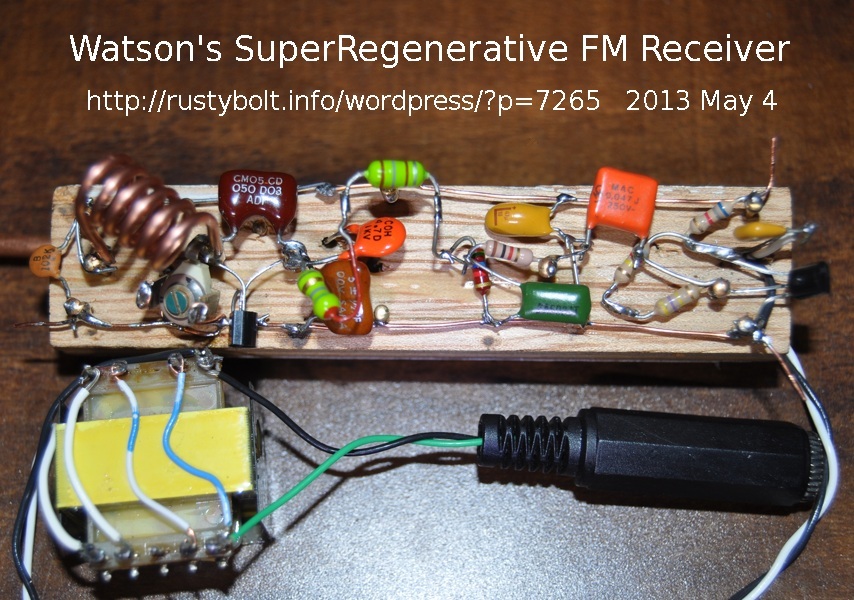 I’ve been thinking about the garage door open alarm project of an earlier blog, and how to get the alarm signal from the door to wherever the alarm beep signal is going to be heard. The distance isn’t far: less than fifty feet or fifteen meters. There are some interior and exterior walls in the way, but I don’t think that will be a problem. The problem is how to receive the signal with a receiver that is low power, and can run for weeks from a single battery. I decided to try a Superregenerative VHF FM band receiver. The schematic I used is found at the end of this Youtube video. It’s a simple two transistor circuit, or I should say one JFET and one transistor. I don’t like to use JFETs because they have such a large variance (10 to 1 or more) in their Idss and Vgs, so the circuit often has to be tweaked to get them to work. In this case the JFET is biased at only a fraction of a milliamp so the variance should not be a problem.
I stuck to the schematic, with the following differences (left to right). The 3.9k, 1 nF and 5 turn coil were the same. The “beehive variable capacitor” he used was not available, so I used a ceramic variable capacitor. The MPF102 with the 5 pF capacitor across it were the same, as was the 5 pF to ground. I changed the 5 pF antenna capacitor to a 4.7 pF, so really no difference. The 4.7 uF bypass capacitor was increased to 47 uF and I used a tantalum cap.
The 100 uH choke was not a good choice because the SRF (self resonant frequency) was below 88 MHz, so I used a 5.6 uH in series with a 180 uH. I used the 5.6k resistor but reduced the 10 nF in parallel to a 5 nF for a little bit more high frequency audio. I used a 1k instead of the 820, again no real difference. I used a .047 uF coupling capacitor, a 2N3904 and a 6.8k, all the same, but the collector voltage was too low with a 330k, and it had to be increased to 1.3 Meg to get the collector voltage up to 4 volts. I added a 0.1 uF to the output to block the DC, and connected all four windings of a 600 ohm transformer in series which is supposed to be 9600 ohms, and I connected a 150 ohm earpiece across the winding at the bottom, closest to ground.
For the antenna on the back, I held a foot long copper tube to the wood with three screws and the lead from the 4.7 pF capacitor passes through a hole in the wood to under one of the screws. The supply voltage was 9V and the current was a whole milliamp. Well. actually 1.1 milliamps. Even so the earpiece can get loud.
Update May 5 – I took a 3 by 3 inch pine board and pounded a headless finishing nail into it, and then drilled a hole in the bottom end of the circuit’s wood so it could fit over the nail and the nail would hold it upright. I noticed that keeping my hands off of it helps reduce the drift off frequency.
I couldn’t tell which direction was minimum or maximum on the tuning capacitor, so I removed it and put in a 1 to 17 pF variable and a 5 pF in parallel. The variable has a clear plastic separator between the plates so I can see what position the plates are at, from fully meshed to all the way out. Now I know relatively where the capacitor is set at. And the 5 pF brought the minimum frequency down to well below 88 MHz, somewhere around 84 or 85 MHz. Now I can set the receive frequency to a point where the TV channel 6 would be, but there is nothing there so there is no interference from other FM stations. It will also tune well above 100 MHz, but this band is crowded so I’ll never need to tune it that high.
The bad thing is that the circuit needs 9 VDC. The exorbitant cost of 9V batteries has led me to build a 1.5V to 9V DC to DC converter, so I need to build one up for this circuit. But the circuit takes only a little over a milliamp, so the converter will have to be a real miser and take in only about 20 to 25 milliwatts, or about 13 to 17 milliamps at 1.5V. That’s a lot less than the typical Joule Thief. But it may be better to use a 1.25V rechargeable cell. I think a shunt regulator using a 9V zener may be the best way to go. I’ve had interference problems with these DC converters in the past, so it may require some effort to reduce the interference.
I’ve noticed that when I have this receiver near another FM radio, it causes interference when they are both tuned to the same station. This is a result of the RF oscillations that are the reason for it being a superregenerative receiver. If I enclose it in a metal case, it might reduce the radiation somewhat, but I suspect that most of the radiation is coming from the antenna, which cannot be enclosed. The solution would be to put a preamplifier between the antenna and the circuit. It would reduce the radiation a lot, but probably not eliminate it. It would also increase the sensitivity of the receiver. The distance from the transmitter is not very far so this preamp is probably not needed for more sensitivity, but only for the radiation reduction. The question is do I want to do the added expense and effort to add a preamp. I think I won’t because this receiver will probably be tuned to a frequency below the FM band and should not interfere with the FM broadcasts as long as it’s kept a reasonable distance away from the other radios.
I’ve been searching for more receivers of this type to see if I could find one that has the preamp. Many of these receivers were designed to be used in the HF bands, 30 MHz and below, and due to the atmospheric noise, the preamp would not be needed since all it would do is increase the noise. So my searching hasn’t been fruitful. More later. I still have to think about the transmitter.
2013-05-02 1 kHz Audio Frequency Oscillator
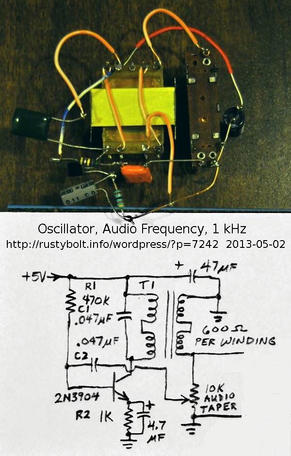 I was wandering around the pages of the Modern Electronic Circuits Reference Manual, a 1200 page tome by Markus, when I happened to see this odd circuit for a signal generator (see the schematic). My curiosity got the best of me, and I knew I had to build one, since I have a whole lotta these transformers waiting to be used for something.
The circuit is simple. The collector load is two of the transformer’s windings connected in series, giving an impedance of about 2400 ohms. 5VDC is supplied to the collector through these windings. The 0.047 uF capacitor (the dark green one at the far left) is across them, forming a resonant tank circuit. The two other windings are connected in series as the secondary winding. One end is grounded, and the other is connected to a 10k pot (the narrow rectangle at the right). the wiper of this is connected to a 0.047 uF DC blocking capacitor, then to the base of the transistor. As the pot is increased, the feedback gets to the point where it’s enough to maintain oscillation. The frequency is controlled by the inductance of the primary winding and the 0.047 uF capacitor across the winding.
The circuit I built was almost the same as the schematic, except for the 470k resistor, which I changed to 560k. But this value would need to be adjusted to accommodate different transistors with different current gains – just about any transistor should work in this circuit. With the 560k, the 1k emitter resistor had 0.9V across it, indicating that there was about 0.9 mA of emitter current.
The first time I powered it up and turned up the feedback pot, nothing happened. I knew that I had the feedback winding connected backwards, so it was negative, not positive. I unsoldered it and soldered it the other way around, and powered it up. When I advanced the feedback pot, I got a sine wave on the o’scope. But it was slightly distorted (more on this below). The frequency was about 1200 Hz when the pot was adjusted for minimal distortion. But it was touchy, a slight change and the sine wave would drop to zero. When it was turned up slightly, the sine wave was a full 5V peak to peak, with some distortion at the bottom. The frequency also dropped, to about 1050 Hz, but that varied depending on the pot setting.
If the circuit is used like this, it would require the feedback pot to be a user settable knob on the front panel, because the amount of feedback would need to be frequently adjusted when the temperature or supply voltage changed or the load was changed. To prevent this, the circuit should have an AGC (automatic gain control) circuit added to it to maintain the gain at just the right point with no need for manual adjustment.
The feedback pot could be adjusted so there was no distortion, but it was near the very end of its low end. I measured the resistance with the DMM and it was only 150 ohms. So the ratio was 150 ohms to 10 k, or a dividing ratio of about 67. The pot would not have been settable if it had been a linear pot. This should be changed to a 10k resistor in series with a 500 ohm pot to give a finer adjustment.
Other modifications
This circuit is just one of many configurations for an oscillator. The feedback winding could be changed to one of the two windings, and the remaining winding could be used for the output. As I said, the frequency will change with different loads. To prevent this, an attenuator should be used between the transformer and the output, with enough attenuation to make the frequency change minimal. Or another transistor could be used as a buffer stage, to isolate the output load from the transformer.
To get the circuit to put out 1000 Hz, it would need to have a larger capacitance across the primary winding. The 0.047 uF cap could be changed or additional capacitance added to it. It should probably be something close to 0.068 uF total.
In an audio oscillator, one disadvantage of using a transformer for the frequency determining element is that it is subject to electromagnetic interference, and is expensive and bulky. If you get this near a power transformer it might pick up some hum, but the core has a metal shield around it on three sides to minimize this problem.
One advantage of the transformer is that if this circuit is going to be used for the modulation of a transmitter, the DC for the transmitter can be passed through the windings with very little power loss. That is why the AM transmitters used a transformer to amplitude modulate the final RF output stage.
2013-04-30 Flashlights And What I See In The Stores
I recently came across some of the pictures that I used in early my watsonseblog, sometime around the mid 2000s. From 2000 when white LEDs were very expensive and difficult to obtain, the LED flashlights (torches) were very expensive. Generally, a LED flashlight with a few 5mm white LEDs would cost several tens of dollars U.S. One that threw a decent beam might cost 80, 100 or more dollars U.S. The manufacturers – I remember Lumileds was one of the first – started developing white LEDs that were larger than 5mm, with power up to 1 watt.
Jump ahead a decade and we can find flashlights with 9 white LEDs on the store shelf for 4, 3, or even 2 dollars, Ten years earlier, just a single one of those LEDs would have cost that much. The prices have come down a lot and the light output has increased dramatically.
One other phenomenon has come about i that time. The overseas companies, especially China and Hing Cong have been making flashlights out of solid aluminum that are inexpensive, put out a lot of light, and use only a single AA or AAA cell, so the cost of operation is low. One would think that it would be very hard to compete with this winning combination.
But the cheap 9 LED lights I see on the store shelf don’t have that one advantage; they use three AAA cells so the cost of replacing the three could be two dollars, more than half the cost of the flashlight.
2013-04-29 Fordex 300 Lumen Flashlight
The LED flashlights I bought in March from Amazon (but shipped from Hong Kong) arrived recently and I’ve had a chance to use them a bit. I paid $5.49 apiece, with free shipping, but I see that the price (as of June 8) has gone down to $4.30, These have a Cree Q5 emitter, and use a single AA cell. The lens on the front slides in and out to allow the light to be focused in a large or small pattern. They said 300 lm but I don’t believe it. The body is black, solid aluminum, with a screw on cap in the rear with the click switch.
Nowadays, the reflector has dozens of squares on it to help diffuse the light pattern. But this LED light has the additional lens and it will focus the face of the LED onto the wall, so I can see the actual pattern of the emitter. But I don’t have to pull the lens out that far; the pattern will stay somewhat diffused. I think that most people don’t like this sliding lens ‘feature’, so they are having difficulty selling them and have to drop the price. I bought them to give to some of my co-workers.
One thing I noticed when I picked this light up was how heavy it was. It has a lot of aluminum in it. The case is aluminum and it’s thick. If I wanted to go on a hike, or take a flashlight somewhere where ones gear has to be light, this is not the flashlight to use.
More about flashlights (torches) in general and what I see in the market currently in my blog here.
2013-04-28 LED Current Limiter Using Zener For Reference Voltage
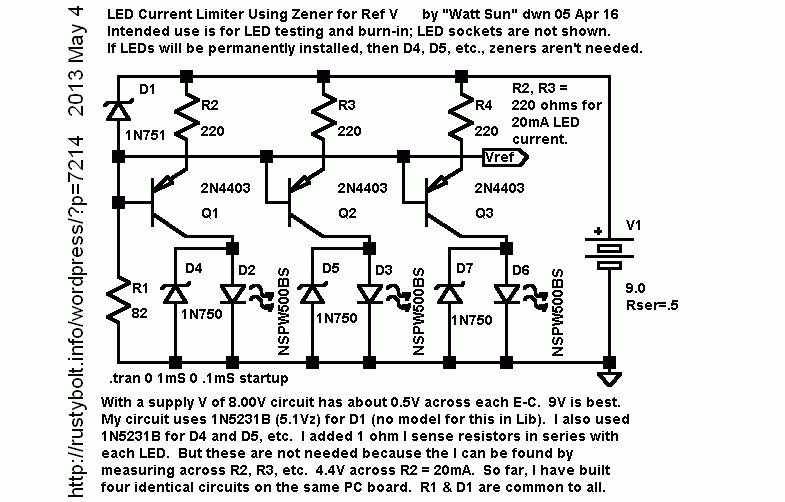 This is an old schematic that I drew in Apr of 2005 using SwitcherCAD III (now LTspice). It is taken from the board I built and put in service for several years as a LED test jig for testing the lifetimes of various white LEDs. Needless to say, most of the white LEDs lasted less than a year, some only a few months before they grew very dim. The only ones to hold up well were the Nichia LEDs.
The circuit has some peculiarities. The zeners across the LEDs are there to protect the transistors from excessive base current. These zeners should be about 3.9 or 4.3 volts, low enough to conduct when the LED fails or has been removed, but high enough to not conduct when the LED is working.
Some of the parts get warm when the thing is left on all the time. It’s best if the supply is held at a constant 9V, to prevent those normally warm parts from overheating.
A Better Alternative
Nowadays, it’s much easier to make a constant current test jig like this. All you have to do is use a 5VDC regulated “wall wart” DC adapter such as the ones used to charge phones. Into it, plug the USB cable cut off from a bad keyboard. Strip off the jacket and shield and use the red and black wires. These should give you + and – 5VDC.
The typical white LED drops about 3.2 volts when there are 20 milliamps flowing through it (the actual voltage varies with temperature). Subtracting that from 5V leaves 1.8V to drop across the current limiting resistor. If you use a 100 ohm resistor, the current will be about 18 milliamps. If you want 20 milliamps, you need a 90 ohm resistor. You can put a 1k resistor across the 100 ohm resistor, and the result will be about 90 ohms, actually 90.909… ohms, which is just about 20 milliamps.
So for each LED you want to test, just add the LED (cathode or flat spot to the black or negative wire) and the resistor (or resistors) between the red wire and the remaining LED lead. A 1/2 amp adapter should be able to handle more than a dozen LEDs.
Here is the text that I wrote for this:
LED Light Output Degradation Over Time
by Watson A.Name 05 May 2 Ver. 050503B
[part of my LED light output degradation over time document -May 3, 05]I got some complaints that I should make some quantitative measurement of the LED light output. So I taped a cone of stiff heavyweight paper over the photocell of my old Weston Master light meter. I can now put the LED at the hole in the tip of the cone and it is held at a fixed distance of 70mm or 2.8″ from the meter, to give consistent readings. The cone also stops most of the ambient light from affecting the readings. And it seems there’s another benefit. The inside of the cone is white paper, so much of the light that comes from a wide angle LED is reflected back down to the photocell, giving a reading that is closer to the LED’s total output. If the cone wasn’t there, some of the light would fall outside of the meter’s photocell.
I’m getting a reading of about 65 to 70 for the cheapo Hong Kong white LEDs at 20mA, and almost 100 for the Nichia NSPW500BS white LED at 30mA. From my ongoing observations of another setup of a pair of each of the HK and Nichia LEDs all connected in series and now running for almost ten months at 20mA, the Nichias have held up well, keeping most of their brightness. But the HK leds have lost so much brightness that they are no good for illumination, and make barely acceptable indicator grade LEDs.
[Schematic description of current limiter circuit]
The circuit has two parts: a zener regulated voltage source and a single PNP transistor ‘current converter’ and resistor for each LED. The voltage source is a 5.1V 1/2W zener and 82 ohm resistor. The Zener cathode is connected to positive, and the anode to the 82 ohm resistor. The other lead of the resistor is to ground. THis combination gives a 5.1V source subtracted from the positive supply.Each of the transistor bases is connected to the 5.1V source. The emitter of each transistor is connected to one lead of a 220 ohm resistor, and the other lead of the resistor is connected to the positive supply. The 4.4V or 5.1V minus .7V is across each 220 ohm resistor, giving 20mA thru the resistor, and this current minus a fraction of a milliamp is the collector current, which is connected to the anode of the LED, and the cathode is grounded.
I originally included a 1 ohm 1/4W resistor in the collector to monitor the current, but I don’t think it’s necessary because the current can be monitored across each of the 220 ohm resistors.
Some of the variation in current is caused by the 5% resistors which are closer to 2%, but much of the variation is caused by the variation in B-E voltage drop from transistor to transistor.
2013-04-27 Low Current, High Performance Joule Thief
Paul got me thinking about the Joule Thief with low battery current. In his nineteenth JT he used the very high performance Fairchild KSD5041, same as the 2SD5041 (Japanese pinout – the center pin is the collector). He thought it was his brightest, and that could very well be. His theory is that the coil should be wound with the maximum number of turns of fine wire.
My assumptions are based on the theory that less is more, less turns allows more current and since the stored energy is equal to the current squared, the lower winding resistance means higher peak current and therefore lower losses, I decided to make up this proof of theory JT using the KSD5041 and the following parts.
Toroid core = YJ41003TC, core O.D. = 3/8″ or 9mm. This is a high permeability core, which, with very few turns, gives the optimum inductance of 100 uH or more. Both windings are 7 turns of solid wire, the primary winding 24 AWG with plastic insulation, the feedback winding 24 AWG enameled. Each winding measured 120 uH.
LED = 5mm Blue, with a 1 ohm resistor in series to measure the current.
The resistor was a 4.7k with a 50k trimpot in series. I found that a 68 pF capacitor across both resistors kept the LED lit even at the higher pot settings, and looked brighter than when I used a 1000 pF. The LED would not light at the higher setting without the capacitor. These were connected between the coil and the base lead of the transistor.
I put a 33 uF bypass capacitor across the plus and minus terminals. I built the circuit on a 1-1/2 by 2 inch piece of scrap wood. I pounded some 5/8 inch brass brads into the wood for terminals and wrapped and soldered the wire leads to them.
I set the supply at 1.5V and adjusted the trimpot to give 25 mA supply current. I measured the voltage across the 1 ohm resistor and found that there was 7.2 mA flowing through the LED.
I removed power and measured the resistors and found the total to be 14.7 k.
I calculated the efficiency at (.007A * 3.3V) / (1.5V * .025A) = 61.6 percent. This is one of the best, if not the best efficiency that I’ve measured for a conventional Joule Thief. A typical JT is around 50%, sometimes 55%. But I have seldom seen one go above 60 percent.
I can adjust the trimpot and get the LED to light from very bright at minimum setting to almost dark at maximum setting. This gives complete control over the battery current, which can make the battery last a lot longer, with some sacrifice in LED brightness.
This shows that it’s possible to get excellent efficiency and performance at low current from a Joule Thief using a high performance transistor.
Update Apr 30 – I experimented with the value of the 68 pF resistor bypass capacitor. I connected an adjustable capacitor in parallel with the 68 pF, and adjusted it until the LED current peaked at a very broad peak. I removed the capacitor and measured it and it was about 130 pF. So I found a 120 pF ceramic disk capacitor and soldered it across the 68 pF, for a total of about 190 pF. I checked the LED current and it was almost 8 mA. But the supply current had also gone up slightly. So I readjusted the trimpot to set the supply current at 25 mA. The LED current was then about 7.8 mA, so the JT circuit was slightly more efficient than it was in the original test above. The total resistance then measured 14.85k.
I’m doing a few more measurements, but the circuit has been optimized.
2013-04-24 NiMH Rechargeables Are Not All That Great
(Written by Watson “Watt Sun” Apr 24, ’05 – this was long before you could buy a cheap LED flashlight at the corner store.)
When I first started making my white LED flashlights, I made some with four cell battery holders because I couldn’t get any three cell holders. Also I bought several regular 4 AA cell flashlights and converted the lamp to three LEDs. In both cases, I made a dummy battery to replace the fourth cell, so they would run on three alkaline cells or 4.5V. The dummy battery in many cases was a piece of half inch wood dowel with screws in each end and a shorting wire between. I also made them from a 6-32 screw 2″ long with nylon washers on the ends.
Later, I got this ‘brilliant’ idea that I could save money by replacing the three AA alkalines with four Ni-MH rechargeable cells. So I removed the dummy cell and put four cheapo AA Ni-MH cells in their place. These generally cost under ten dollars for four cells, sometimes less if I bought them with a charger on sale. Many of the sets of four AAs were from my digital camera, for which I buy a new set every year or less after a dozen or two recharges. I just figure that it’s prudent to keep a fresh set or two in the camera, and use the older sets for the flashlights.
I left several of these flashlights around the house in areas like the closet or cupboards to take a quick look in the dark corners. They stay there for weeks at a time without getting used, with a minute or two use on occasion. I’ve noticed that they all suffer from the one bugaboo of rechargeables, the loss of capacity over a few months’ time. I recharge them every few months and even though they get used little, they need a recharge a few months later. And it’s plainly obvious: they put out little light when they get discharged.
I could go back to the three alkalines without any problem. This would save having to recharge them every few months. One reason I hesitate to do this is because I’ve found that the alkalines often leak when stored a long time, especially during the warm summer months. I’ve never had a Ni-MH leak, but I’m not saying it can’t happen. So I’m trading the inconvenience of having to recharge for the reduction of damage to the flashlights.
I’ve purchased some plastic battery storage boxes to hold the spare sets of AA cells once they’re recharged. I’ve had to tape a label on the front to write the recharge date, so I know when it’s time to recharge them after a few months. If I don’t, then I end up with almost dead batteries more often than not.
