default

2013-08-05 Regenerative Receiver Is Half Tube, Half IC

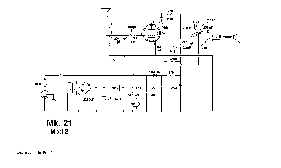
Mk. 21 Mod 2

Click more than once to enlarge.

Leonard Meek came up with this regen receiver that uses a vacuum tube for the RF section and the ever popular LM396 for the audio section.  I decided to write my concerns about this circuit in this blog.  This schematic was posted to the files section of the Yahoo group Regenrx2 (Regenrx Overflow).

One major concern I have is with the power supply.  It is connected directly to the AC line, and this can be dangerous.  But besides this safety hazard, the DC voltage at the 22 uF that’s after the 1N4006 rectifier is totally dependent on the AC line voltage.  Meek didn’t specify what the AC line voltage was supposed to be, so if an experimenter in those parts of the world where the line voltage is 220V builds this and it was designed for 117VAC, the DC voltage will be excessive and will probably damage the circuit.  Likewise, the voltage would be too low if it was designed for 220VAC and plugged into a 100 VAC (Japan) or 117VAC (U.S.A.) line.

So one of the first things I would do is put the power supply after the transformer, so the AC line voltage would be correct as long as the AC line voltage is the same as the transformer’s primary.

For the following I will have to make an assumption: the AC line voltage is 117VAC.  When this is rectified and filtered, the voltage will be approximately 170VDC.  Notice that the 10k resistor is between the two 22 uF filter capacitors.  Then there is a 10k potentiometer after the second 22 uF, so the two 10k resistors divide the voltage in half, and the maximum voltage that can be at this point is 85 volts DC (the wiper of the pot goes to a grid which draws no current).  Then the 27k and 47k resistors go to the tube,which adds a load to the circuit, so the maximum voltage is somewhat less, probably 75 to 80 volts DC.

So far, we know that the B+ voltage for the tube is somewhere around 75 to 80 VDC, and the audio output has its own transformer, full wave rectifier, filter capacitor and 12V regulator.  There are two ways to get rid of the direct connection to the AC line and get both of these voltages from the transformer.

One is to remove the full wave bridge rectifier and change it to a half wave rectifier, so that one end of the transformer’s secondary can be connected to ground.  A half wave rectifier using a single diode will work fine for the audio output because any excessive ripple is filtered out by the voltage regulator.  Then with one end of the transformer’s secondary grounded, we can use a voltage quadrupler to go from about 18VAC to 72 VAC for the B+.

Another way to do this is to use a small 117VAC to 24VAC transformer, and turn it backward so that the 24VAC winding is connected to the 18VAC secondary.  The output will be the primary and it will then be rectified, filtered and regulated to get the power for the audio output.

One other problem that I see is the lack of labeling and a legend.  The 10k resistor in the power supply will have about 90 volts across it, and it will have to dissipate 0.81 watt.  There is nothing on the schematic to tell the average experimenter that they cannot use a quarter watt or even a half watt resistor because it will overheat and burn out.  The resistor needs to be at least 1 watt.  The same with the potentiometer, it must be able to handle at least 1 watt.  And there should be a legend that says something like “All resistors are 1/2 watt, 5% unless otherwise specified.”

I have to say that these regen receivers are relics of a bygone era.  There are almost no electronics today that use vacuum tubes, and especially combinations of vacuum tubes and solid state like the LM386.  Tubes work, but they are notoriously inefficient, and definitely not ‘green’.  I would sincerely recommend avoiding tubes just for that reason, not to mention they die a slow death as they are used.  The only real advantage they have over solid state is if the receiver is connected to an outdoor antenna, the tube receiver will survive a lightning storm, whereas the solid state receiver may get damaged.  But a properly designed solid state receiver will have protection against those storms, and this disadvantage will not be a problem.

But for some, “firebottles” have an attraction and they just have to experiment with them.

default

2013-08-04 A Low Voltage JT Using 2SK170 JFET

Fellow JT experimenter Quantsuff has been experimenting with a Joule Thief using the 2SK170 JFET, and it runs at 131 millivolts (0.131V), powered by a solar PV cell lit by a table lamp.  This is a very good JFET for low voltages; I made a similar circuit a while back and it ran at several tens of millivolts, but I had to put several JFETs in parallel to get enough current to increase the LED brightness.

Some things I learned (more like a large dose of reality).

Let’s say, for example, that the solar PV cell is putting out 150 millivolts or 0.15 volt.  This is one tenth of the 1.5V AA cell.  If the average Joule Thief uses 75 milliamps at 1.5V, then at 0.15V, it will need ten times as much current, or 750 milliamps, to put out the same light.  But in order to draw ten times as much current at one tenth the supply voltage, the total JT resistance must be reduced to 1/100.

This means that all the wiring must be heavier gauge wire, and the wires should be kept short.  The coil should have less turns of heavier wire.  QS used a proto board for his circuit.  Each contact in these boards may have a resistance of several milliohms, so the voltage drop (AKA IR drop) across the contacts can add up to a large percentage of the supply voltage.  Changing to mechanically sound joints that are soldered good will greatly reduce the voltage drops.

The 2SK170 JFET handles up to 20 mA, but the 2SK170BL that I have are all rated 6 to 12 mA, so on average somewhere around 8 milliamps.  I could see that this was going to be a problem because it will take almost a hundred of them in parallel to get the 750 milliamps that I mentioned above.  That’s why the circuit board in the picture in the link above showed six of them in parallel, which was just a start.

Remember that when you’re dealing with voltages this low and currents this high, every little bit helps.

default

2013-08-02 Joule Thief, MOSFET Test

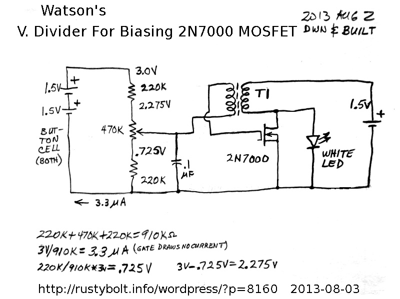
I built a Joule Thief using a 2N7000 MOSFET with the white LED across it, a standard coil (see below) and a voltage divider connected to the gate.  I was trying to find out more about the MOSFET, such as the gate bias voltage needed to make it run on a 1.5V AA cell.

DSC_0461S5The voltage divider was a 470k trimpot with a 220k resistor at each end, and all three connected in series across the two button cells.  The wiper of the trimpot was connected to the feedback winding, and the other end of the feedback winding was connected to the gate of the 2N7000.  According to the calculations I should be able to adjust the voltage from 0.725V to 2.275V, which is the gate bias that is applied to the 2N7000 .  If I try to measure this with a DMM, the DMM’s 10 meg internal resistance in parallel with the V divider will reduce the actual voltage by a few percent.  Also, the actual voltages will depend on the condition of the alkaline button cells, which are more than 1.5V when fresh.  The total current through the 470k trimpot and two 220k resistors is 3.3 microamps (there is no current flowing through the gate), and the button cells should last for a long time, probably several years.

The standard coil is a Fair-Rite 2673002402 core with four 16 inch lengths of 30 AWG solid enameled magnet wire wound quadrifilar.  Three of the four windings were connected in parallel and used for the primary winding, the fourth was the feedback winding.

As I advanced the trimpot from 0 volts, the LED turned on at 1.860 V, and as I turned the trimpot back to zero volts, the LED turned off at 1.385 V.  There was almost a half volt of hysteresis [see Note] there, where the LED brightness varied a bit.  I turned the bias voltage up to about 2 volts and the supply current was about 27 milliamps at about 1.5 volts.

Update Nov 29 – I did more experimenting with the values of the resistors on the ends of the pot, and decided on some more optimum values.  I tried various values to get the pot to cover a range where the LED would be dark at  the lowest voltage setting, and get very bright at the highest setting [see note below].  I tried values higher and lower that these, and decided on a compromise.  The bottom resistor should be increased from 220k to 330k, which will bring the minimum voltage up.  The top resistor should be decreased from 220k to 100k, to bring the maximum voltage up.  What I wanted was to be able to adjust the supply current from below 10 mA to above 50 mA, which gave the LED low to high brightness.  These values are selected for this particular MOSFET, and if a different one, even if the same type is used, the values may have to be changed.  This is because FETs in general have a very wide spread in their turn-on voltage and the voltage that gives maximum current.   I think if I was going to do this again, I would use two more 470k pots, one on each end of the existing pot, and adjust them for optimum values.  Then measure both and replace them with the closest values of fixed resistors.

Note: When the pot is adjusted, the turn-on voltage may be higher, for example 1.8 V, but the turn-off voltage may be lower, 1.4 V for example.  This difference, known as hysteresis, means that the pot may be set at 1.5V to have the low brightness, but if the power is interrupted, the LED will not restart.  Something, such as a pot or switch must be added to give the voltage needed to overcome the hysteresis.

default

2013-07-28 Humorous Headline

P1030781SI was walking by the newspaper and noticed the headline, and after a few steps it hit me: a play on words.  I thought it was cute in a humorous way.

default

2013-07-27 Antique Manual Telephone Switchboard

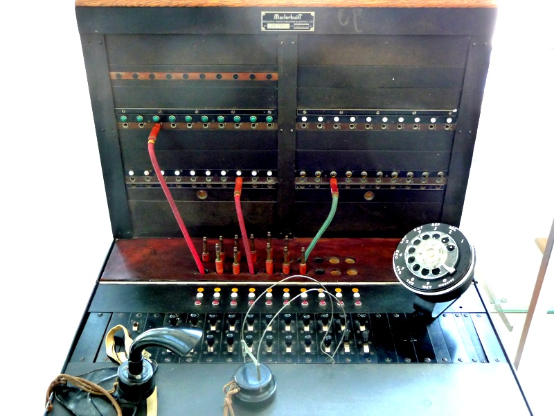
P1030773SI took these pictures at the Orange County Sheriffs Training Academy located on the site of the Tustin Marine Corps Air Station, near the huge blimp hangars.  This seems to be a new addition to their ‘museum’ collection, which includes such things as weapons and improvised explosive devices such as the often seen alarm clock with sticks of dynamite (they’re all disarmed).

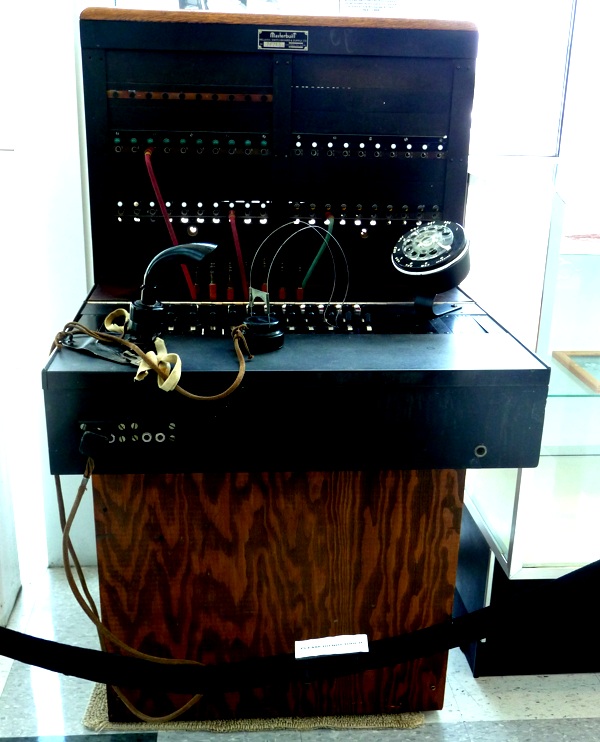
P1030774SThe old manual switchboard demanded that a person be available to do the job.  Some of these switchboards were installed in the corner of a small store in a small town and manned by a part time operator who also served as the clerk of the store and the town’s postmaster.  This usually limited the service time to daytime hours.  Not to mention secrets tended to spread all over town.

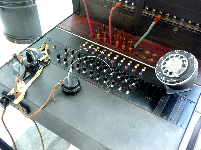
P1030775SOne has to appreciate how far the world has come since the days when the only way to talk to someone down the street or across the country was by asking another human being to connect you up.  Nowadays, you can talk into your phone ans some impersonal voice recognition software tells you it’ssorry, please repeat that, and after a few times finally does connect you to a real human being.  But often we’re not so lucky: we get lost in a maze of verbal menues and can’t get anywhere.

P1030776SMaybe the old switchboards weren’t so bad, after all.

default

2013-07-26 Joule Thief E Field Detector Cont’d

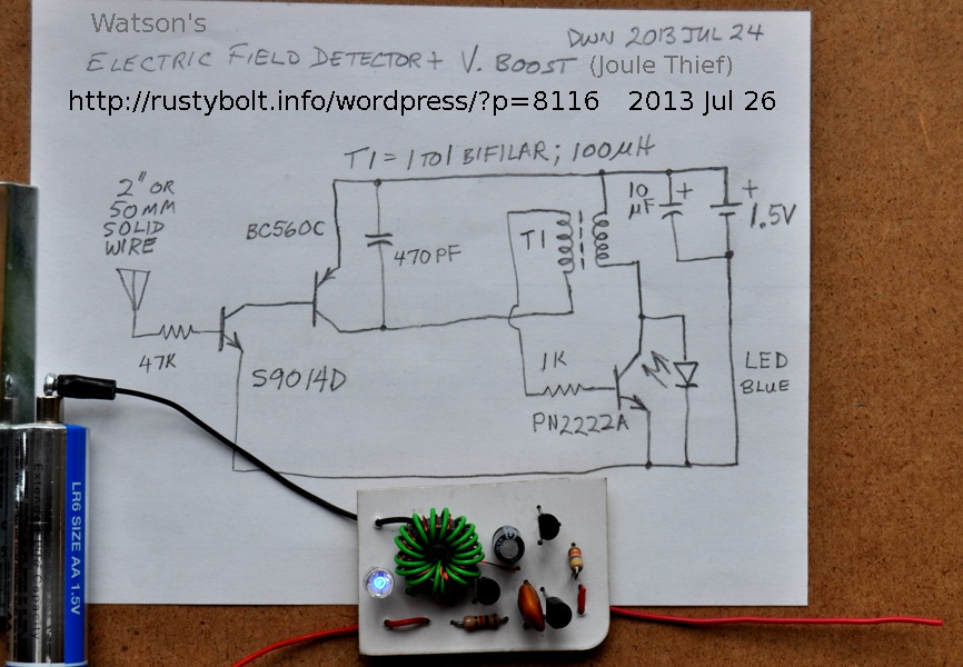
DSC_0434S4This is a continuation of my previous blog.  I drew up a circuit (see the photo) and then built it, and I’ve been experimenting with it a little, and have some encouraging results.  Time for another blog.

As can be seen, the blue LED is glowing dimly.  I originally used an alligator clip for the antenna but its surface area was larger and caused the LED to light much brighter, which made it more difficult to tell if the E field was changing.  I soldered the short wire on and it was much dimmer, enough to tell that the circuit was working but not enough to confuse things.

The circuit calmed down, but seemed erratic when I walked around with it on the clipboard.  I took a single step, and the LED lit brightly.  I raised my foot up and the LED lit brightly.  It was so sensitive that it was detecting the change in the electric field in my body when I was walking on the wood floor.  Dang, that’s sensitive!

If I put the antenna close to electrical wiring, the LED lights up brightly.  If I walk across the tile floor the LED lights up but not as bright as the wood floor.  That seems logical, since the tile is more conductive and should build up less charge on the soles of my shoes.  It used to be that one of these would really light up if it was brought near the face of a CRT monitor or TV, but I don’t have any CRTs, everything I have is a flat panel display.

If I rub the armrest of a chair to build up a charge, the LED dims when I bring it closer, and gets brighter when I move it away.  I’m thinking that means the charge is negative, and moving it away reduces the negative or increases the positive current in the base of the SS9014.  When I hold the circuit, with my finger on the battery negative, and I rub the armrest and move my hand toward it and away from it, the LED gets brighter and dimmer.  I rub a plastic water bottle across my pantleg and then bring it near (an inch or two) the antenna and the LED gets dimmer when it approaches and lights up brightly when it moves away.  The weather has been more humid than usual, yet the circuit is still very sensitive.  My guess is that when the humidity gets lower, it will be even more sensitive.

The Evening News announced that the record for  rainfall for July here in So Cal was broken – we had 0.09 inches.  Big deal!  Today was overcast all morning and finally cleared up late this afternoon.  No rain today, but it rained earlier this week.  The humidity is still above normal.

More About The Circuit

I built the circuit on a piece of cardboard, and I’ve used cardboard previously, and found that it absorbs some moisture and becomes slightly conductive.  In this case, the cardboard is from the back of a package and it is glossy on both sides, probably with glossy ink.  I think that makes it less absorbent and it isn’t as conductive as plain paper.

I used the SS9014D, which is a very high current gain NPN transistor, about 600 or more.  The BC560C is also very high gain, so the amount of current gain from the input of the first transistor to the output of the second transistor is probably hundreds of thousands.  If a 2N3904 and 2N3906 are used instead, the circuit should work, but it won’t be as sensitive, I believe.  My circuit takes less than a milliamp at the 1k and coil winding, so if I divide that by 360 thousand, I get 2.5 thousandths of a microamp or 2.5 nanoamps.  A microamp is a very small amount of current and this is much less than that – 1/400th of a microamp.

Another important point to remember is that the transistors are current operated devices.  The antenna must cause a flow of current in the base to emitter junction in order to get a flow of current through the emitter  to the collector.  This is in contrast to the FETs such as the 2N7000, which has a gate that is sensitive to voltage.  Thus if you move the antenna on this circuit, it will change the E field, and that change causes a current to flow to or from the base – the LED lights or dims.  But once the movement stops, the E field stops changing and the current stops – the LED stops changing.  With the 2N7000 MOSFET, the antenna would cause an electric field to build up on the gate (it’s a field effect transistor), and the 2N7000 would turn on and the LED would light up and stay lit, until the field changes

The ANTENNA

I used a short 2 inch (50mm) piece of 24 AWG (0.5mm) solid insulated wire.  It tends to get bent a bit, so a stiffer wire would probably be better.  I originally used an alligator clip temporarily, but the circuit was too sensitive and it caused the LED to stay on most of the time.  When I changed to the 2 inch wire, the LED stayed off most of the time and the circuit was a bit less sensitive.  If you use a piece of heavier wire, or paper clip, it may cause the circuit to be more sensitive.  If it does, just cut off a bit of it and retry it, and if it helps, you’re good to go.  If not, then you may want to make it a bit shorter. If you cut off too much, just put a new one on or solder an extension on, or make it a T shape.  You can tell people that the crooked design of the antenna is what makes the circuit work.  “It’s like a water witching rod.  The tree branch has to be just so.”  Heh-heh!  Read about that here.

Also, if you use lower gain transistors such as the 2N3904 and 2N3906, then the circuit may be more sensitive with a longer wire.  You’ll just have to experiment with it to see what’s the optimum length.

I think that if the antenna wire has insulation, it will be more sensitive. The antenna wire picks up the electric field using its capacitance to the surrounding air, and if insulation is added, the plastic has higher dielectric constant than air, so it may increase the capacitance, which in effect should increase the sensitivity.  In any case, you can compensate by changing the length of the wire.

default

2013-07-21 Joule Thief EMF Detector

I was watching this Youtube video of a Joule Thief that is used as an EMF detector.  Actually it is detecting the electrostatic field, not the electromagnetic field.  If it had a pickup coil instead of an antenna, then it would be detecting the electromagnetic field.  Anyway, it looks like he is trying to trace the wiring in the wall.  That’s a very good idea.  Except it wouldn’t work if the wiring was inside of metallic tubing or flexible metallic cable.

I thought that if the circuit was changed to turn the LED off when a field was detected, then the Joule Thief could be used for a night light.  But then I realized that it would be easier if the circuit used a CdS photocell instead, which would turn it off when the light was on, and also when the ambient light was daylight.

The circuit is called a Joule Thief, but it differs from a true JT.  The coil doesn’t have a feedback winding, and actually the whole circuit doesn’t have any feedback – it’s operating ‘open loop.’  The circuit depends on  the AC power line field that is present at the antenna to give the circuit something to sense.  It has no bias resistor on the input so it acts as a detector.  In fact, the whole circuit has no resistors, which means there is nothing to limit the current.  If the input gets shorted to the battery negative excessive current will flow and one, the other, or both transistors will most likely get damaged.  It would be an improvement if there was a resistor between the antenna and the base, and another resistor elsewhere in the circuit to limit the current.

As the pulses of current from the first transistor pass through the second transistor, they are not enough to light the LED.  When the current stops, the back EMF or inductive kick of the coil creates enough voltage to cause the LED to conduct for a brief time.  It’s not very bright – there are only fifty or sixty short flashes every second.

What this all leads to is that the circuit would be better if the coil had a feedback winding and acted like a true JT, with the first transistor turning on the base bias to the JT.  It could be more sensitive, especially if the two transistors fed a true JT instead of directly feeding the LED.

I drew up a schematic, but I’ve yet to get the soldering iron heated up and build it.  All in due time.  UPDATE: I built it and I’ve started another blog about it.

default

2013-07-20 Tech Preservation Website

I found this website that saves many of the old schematics and pictures from the past.  It’s called techpreservation.dyndns.org and this link shows only the ones beginning with L.  I’m sure that there are many more, such as the ones beginning with J for Joule Thief.

I see many of the schematics and pictures that I blogged in my late, great watsonseblog.  I also see some of Quantsuff’s schematics.  Later I did a lot of perusing and found many pictures of antique radios.  I also found pictures of the early computers such as the Whirlwind.  Other interesting pictures, such as schematics of various electronic devices, including Heathkit stuff.

default

2013-07-12 Blocking Oscillator Schematics From 1965

DSC_0431BW2

Click more than once to enlarge.

DSC_0432BW2JPG

Click more than once to enlarge.

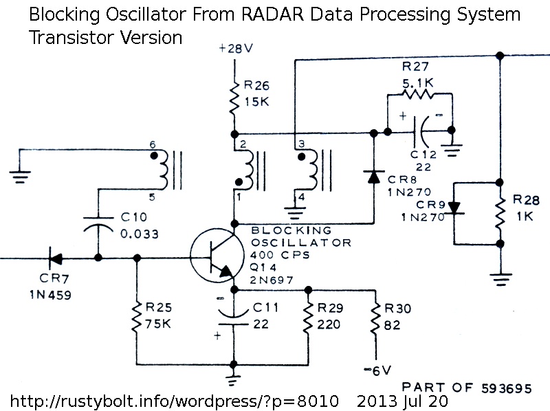
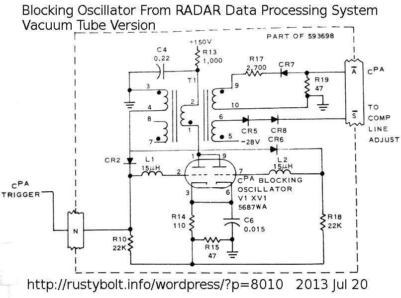
These schematics are from a RADAR Data Processing System used in the military in the early to mid 1960s.  They show how the vacuum tube and transistor versions were designed.  I’m blogging them to show that the blocking oscillator circuit, similar to the Joule Thief, has been around for a very long time.

default

2013-07-11 Watson’s Pet LED Garden Rock

DSC_0423S2I came across this in a “99 cent” discount store, for a dollar.  The UPC code is 39277 75124.  They also had the standard garden lights for $2, with the plastic stake to poke into the ground.  I bought one of those and opened it up, and found that they had gone cheap, and used a AAA cell, instead of the earlier ones with an AA cell.

With this garden rock, I decided that for a dollar, I could get a solar photovoltaic cell, a white LED with a reflector and a battery, so it was worth the investment.  I figured that it would have a AAA cell inside just like the $2 garden lights.  The thought never occurred to me that the case was so small that the AAA cell might not fit inside (but I did managed to squeeze one in diagonally).

Everything was underneath the solar cell, which was hot glued into the case.  I pried it off gently with a small screwdriver so as not to chip or break the solar cell.  The circuit board isn’t worth anything to me; the black blob on it covers all the silicon devices, and the 470 uH choke is a poor choice for a Joule Thief due to its high resistance and high losses.

But the rechargeable cell is really a big disappointment.  I was expecting something bigger than a little green button cell.  I don’t see how these could run for more than an hour or so after the sun sets.  My guess is that the circuit was designed for lower current drain on the button cell, and much lower LED light output, of course – that’s the only way they can make the button cell last for more than an hour or so.    If so, then replacing the button cell with a larger AAA cell will not increase the light output, and there’s no way to modify the circuit for more light output.  The label says it’s a 1.2V AG13 rechargeable cell, and it’s not replaceable.  It says 40 MaH, and charge is 4 mA for 14 hours.

The circuit shuts off the LED when there’s light on t he solar cell, and it’s quite sensitive.  Even the light inside the house is enough to shut it off.  And this light is too low to recharge the battery.  This leads me to conclude that if the experimenter wants to experiment, the circuit needs to be replaced.

Should I go back and buy a few more?  I really like the reflector, which costs two dollars if I order them from online.  That’s really expensive considering the companies that make these rocks are paying only a few cents for them.  So I think it’s worth buying them just for the reflector, if I can get it out without damaging it.  The solar cell is worth a few dollars.  The switch can be reused.  But the button cell, well, if I could get three of them and put them in series, and charge all three with a 4V solar cell, then they might be able to run a single LED.  I think what might be a solution is to put a new board inside, and use a bigger battery.  The case is really ugly, so I may salvage the solar cell and LED/reflector and use some other container, like an Altoids tin.  I’ll have to do some measurements on the solar cell to find out how much current it can put out in sunlight.  I may need two or more solar cells to charge a discharged AA cell during the daytime.

© RustyBolt.Info/wordpress
CyberChimps