


Click more than once to enlarge.
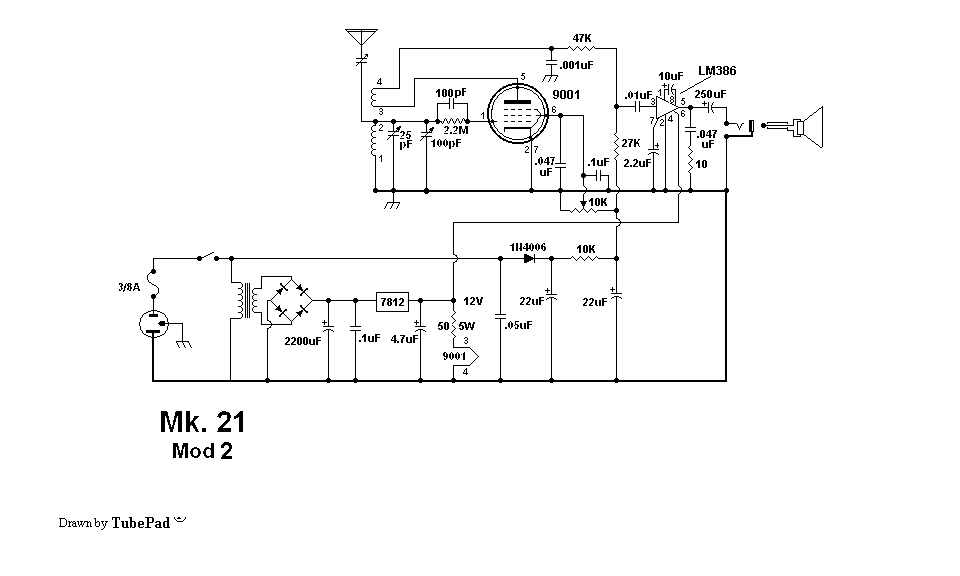
Leonard Meek came up with this regen receiver that uses a vacuum tube for the RF section and the ever popular LM396 for the audio section. I decided to write my concerns about this circuit in this blog. This schematic was posted to the files section of the Yahoo group Regenrx2 (Regenrx Overflow).
One major concern I have is with the power supply. It is connected directly to the AC line, and this can be dangerous. But besides this safety hazard, the DC voltage at the 22 uF that’s after the 1N4006 rectifier is totally dependent on the AC line voltage. Meek didn’t specify what the AC line voltage was supposed to be, so if an experimenter in those parts of the world where the line voltage is 220V builds this and it was designed for 117VAC, the DC voltage will be excessive and will probably damage the circuit. Likewise, the voltage would be too low if it was designed for 220VAC and plugged into a 100 VAC (Japan) or 117VAC (U.S.A.) line.
So one of the first things I would do is put the power supply after the transformer, so the AC line voltage would be correct as long as the AC line voltage is the same as the transformer’s primary.
For the following I will have to make an assumption: the AC line voltage is 117VAC. When this is rectified and filtered, the voltage will be approximately 170VDC. Notice that the 10k resistor is between the two 22 uF filter capacitors. Then there is a 10k potentiometer after the second 22 uF, so the two 10k resistors divide the voltage in half, and the maximum voltage that can be at this point is 85 volts DC (the wiper of the pot goes to a grid which draws no current). Then the 27k and 47k resistors go to the tube,which adds a load to the circuit, so the maximum voltage is somewhat less, probably 75 to 80 volts DC.
So far, we know that the B+ voltage for the tube is somewhere around 75 to 80 VDC, and the audio output has its own transformer, full wave rectifier, filter capacitor and 12V regulator. There are two ways to get rid of the direct connection to the AC line and get both of these voltages from the transformer.
One is to remove the full wave bridge rectifier and change it to a half wave rectifier, so that one end of the transformer’s secondary can be connected to ground. A half wave rectifier using a single diode will work fine for the audio output because any excessive ripple is filtered out by the voltage regulator. Then with one end of the transformer’s secondary grounded, we can use a voltage quadrupler to go from about 18VAC to 72 VAC for the B+.
Another way to do this is to use a small 117VAC to 24VAC transformer, and turn it backward so that the 24VAC winding is connected to the 18VAC secondary. The output will be the primary and it will then be rectified, filtered and regulated to get the power for the audio output.
One other problem that I see is the lack of labeling and a legend. The 10k resistor in the power supply will have about 90 volts across it, and it will have to dissipate 0.81 watt. There is nothing on the schematic to tell the average experimenter that they cannot use a quarter watt or even a half watt resistor because it will overheat and burn out. The resistor needs to be at least 1 watt. The same with the potentiometer, it must be able to handle at least 1 watt. And there should be a legend that says something like “All resistors are 1/2 watt, 5% unless otherwise specified.”
I have to say that these regen receivers are relics of a bygone era. There are almost no electronics today that use vacuum tubes, and especially combinations of vacuum tubes and solid state like the LM386. Tubes work, but they are notoriously inefficient, and definitely not ‘green’. I would sincerely recommend avoiding tubes just for that reason, not to mention they die a slow death as they are used. The only real advantage they have over solid state is if the receiver is connected to an outdoor antenna, the tube receiver will survive a lightning storm, whereas the solid state receiver may get damaged. But a properly designed solid state receiver will have protection against those storms, and this disadvantage will not be a problem.
But for some, “firebottles” have an attraction and they just have to experiment with them.


