


I built a Joule Thief using a 2N7000 MOSFET with the white LED across it, a standard coil (see below) and a voltage divider connected to the gate. I was trying to find out more about the MOSFET, such as the gate bias voltage needed to make it run on a 1.5V AA cell.
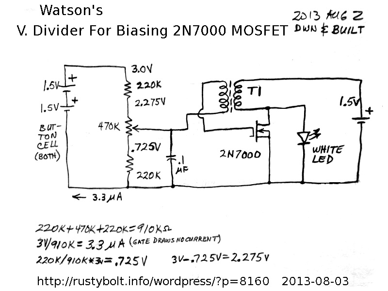 The voltage divider was a 470k trimpot with a 220k resistor at each end, and all three connected in series across the two button cells. The wiper of the trimpot was connected to the feedback winding, and the other end of the feedback winding was connected to the gate of the 2N7000. According to the calculations I should be able to adjust the voltage from 0.725V to 2.275V, which is the gate bias that is applied to the 2N7000 . If I try to measure this with a DMM, the DMM’s 10 meg internal resistance in parallel with the V divider will reduce the actual voltage by a few percent. Also, the actual voltages will depend on the condition of the alkaline button cells, which are more than 1.5V when fresh. The total current through the 470k trimpot and two 220k resistors is 3.3 microamps (there is no current flowing through the gate), and the button cells should last for a long time, probably several years.
The standard coil is a Fair-Rite 2673002402 core with four 16 inch lengths of 30 AWG solid enameled magnet wire wound quadrifilar. Three of the four windings were connected in parallel and used for the primary winding, the fourth was the feedback winding.
As I advanced the trimpot from 0 volts, the LED turned on at 1.860 V, and as I turned the trimpot back to zero volts, the LED turned off at 1.385 V. There was almost a half volt of hysteresis [see Note] there, where the LED brightness varied a bit. I turned the bias voltage up to about 2 volts and the supply current was about 27 milliamps at about 1.5 volts.
Update Nov 29 – I did more experimenting with the values of the resistors on the ends of the pot, and decided on some more optimum values. I tried various values to get the pot to cover a range where the LED would be dark at the lowest voltage setting, and get very bright at the highest setting [see note below]. I tried values higher and lower that these, and decided on a compromise. The bottom resistor should be increased from 220k to 330k, which will bring the minimum voltage up. The top resistor should be decreased from 220k to 100k, to bring the maximum voltage up. What I wanted was to be able to adjust the supply current from below 10 mA to above 50 mA, which gave the LED low to high brightness. These values are selected for this particular MOSFET, and if a different one, even if the same type is used, the values may have to be changed. This is because FETs in general have a very wide spread in their turn-on voltage and the voltage that gives maximum current. I think if I was going to do this again, I would use two more 470k pots, one on each end of the existing pot, and adjust them for optimum values. Then measure both and replace them with the closest values of fixed resistors.
Note: When the pot is adjusted, the turn-on voltage may be higher, for example 1.8 V, but the turn-off voltage may be lower, 1.4 V for example. This difference, known as hysteresis, means that the pot may be set at 1.5V to have the low brightness, but if the power is interrupted, the LED will not restart. Something, such as a pot or switch must be added to give the voltage needed to overcome the hysteresis.


