default

2013-08-16 Ken’s Mini Motorcycle

P1030823S2Hey, Ken!  I was down the street and saw that someone threw this out in the trash.  You said you wanted to get a motorcycle but your wife wouldn’t let you.  I was going to bring it over to your house so you could ask your wife it you could keep it.   🙂

I had a dentists appointment and I couldn’t take time to look at it, but it looks just like a real motorcycle.  The chest of drawers behind it is 3 feet high at the most; the handlebars aren’t even as high as my kneecap!  It’s so cute!  She might let you keep it. but your kids might want to ride it and it could have something wrong with it, and that could be dangerous.  So I left it alone.  Maybe I should’ve taken it home, then put it on eBay and make a few bucks.

It looks something like this one, but maybe smaller?

http://www.amazon.com/RAZOR-15130661-Razor-Pocket-Betty/dp/B000I44P90/ref=sr_1_1?ie=UTF8&qid=1376784101&sr=8-1&keywords=kids+motor+scooter

default

2013-08-15 Indestructible Cell Phone

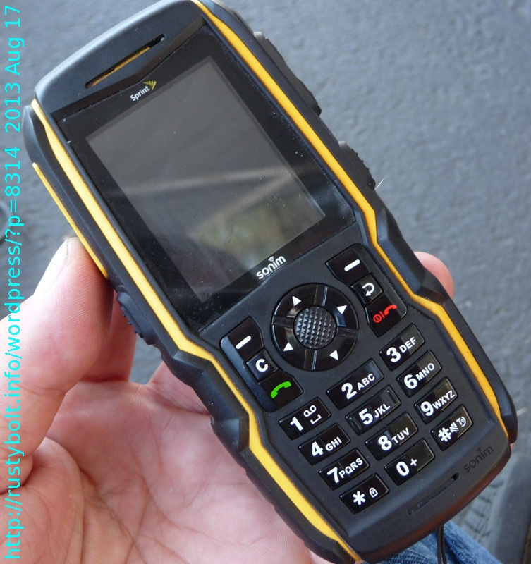
P1030812S2The guy at our computer club let me take a picture of his Sonim cell phone.  These are advertised as indestructible, and they show Youtube videos of them abusing it as a ball, and a truck running over the phone.  The finally killed it with a bullet.

default

2013-08-14 Getting a LED to Simulate a Light Bulb

I touched upon this subject in my late, great watsoneblog, but not since then, I believe.  What I came up with back then was simple and effective.  I wanted to change the abrupt turn on and turn off of the LED into the much slower turn on and turn off of an incandescent light bulb.  The light bulb filament takes several tens of milliseconds to heat up and cool down, so it’s slower than the LED.  If you watch the tail lights and CHMSL (center high mounted stop light) of the car in front of you, you will see the CHMSL LEDs turn on and off almost instantly, and the stop light bulbs turn on and off delayed somewhat compared to the CHMSL.  Obviously this doesn’t work if all of the lights are LEDs.

I tried the easy way to get the LED to fade on and off, I put an electrolytic capacitor across it.   I don’t remember what the value was, but it was well over a hundred microfarads, I believe.  When there are a lot of LEDs, this capacitor can take up a lot of room and add cost to the circuit.

Another method that is more commonly used nowadays is to control the LED with a microcontroller and software.  This allows the LED to be pulse width modulated, so that the current and energy wasted can be minimized.  This allows the on time of succeeding LEDs to overlap the one before it, so that it can give a realistic simulation of an incandescent light bulb.  Aki, the LED artist, does this with his amazing and incredible LED projects.


default

2013-08-13 Getting A Design Made Into A PC Board

Paul sent me an email with some questions about making a generic Joule Thief PC board  and getting it made into some PC boards.  I advised him about using the free ExpressPCB software to design the schematic and PC board, and their service to fabricate the PC board.  They charge 66 dollars U.S. for a “Miniboard” which consists of three boards, each 2.5 inches (63.5 mm) by 3.8 inches (96.5 mm).  Each board can have double layers and if you want silkscreen they charge extra.  Check their website for all the options and prices.

One of my answers was:

They want to [lock you into their service], but Futurlec say that they accept ExpressPCB files.  I’ve never used their service to find out, though.  Some PCB fabs charge a fixed setup fee and then by the square inch or cm.  if you do the numbers, you may find that the fixed setup fee makes the cost higher than ExpressPCB until you go over a certain size, which may be more than you want to buy, especially if you have small PCBs.

So you have to do some calculations to find out how much it’s going to cost per board with all the fees and stuff.  I remember Akimitsu Sadoi (the LED Artist) emailed me about a service that he uses, but I can’t remember the name.  I think it aggregates several members’ boards and submits them periodically, but the service accepts Gerber files, which require Eagle CAD (free) software or other similar s/w to generate.  And as far as I know, there is no way to convert ExpressPCB designs to Gerber, so all of my designs would have to be redone using Eagle.  And I don’t have a Windoze PC at home to do any designs, ExpressPCB OR Eagle.

Galaxy And Proselytizing

I bought a Galaxy S4 last weekend, from Google Play for $701.  I stopped at Wal-mart this evening and bought the T-Mobile SIM only package for $40 which gives me unlimited test and data, no contract, but only 100 minutes a month talk, for $30 a month with T-Mobile, which I already have.  I went to the T-Mobile store and they don’t offer this package, they want you to sign up for the full unlimited everything for $60 a month.  My existing cell phone plan has only 300 minutes, and I seldom go over 100 minutes a month, so I’m okay with this plan.  Wal-mart has other plans, too for various prices, but this particular plan is only offered in store for some reason (probably because if people could get it online, the T-Mobile stores would lose a lot of business!)

My point is that I do have a Windoze PC at work, but I’m mostly away from the office and I already use the iPod and WiFi for some stuff, but I and most everyone else is going Mobile and Windoze is becoming a minority OS, and all the software that has been Windoze only is becoming less and less accessible.  One time not long ago Microsoft Windoze had 80% of the OS, with the remaining 20% split up between Macs and Linux users.  Now the number of devices out there running Android and iOS has far surpassed the number of desktops and laptops, something in the order of billions of them worldwide.

The resolution of the Galaxy S4’s screen is 1920 by 1080, better than my (less than a year old) desktop with a touch screen.  People are carrying around their tablets (iPads, etc.) that do just about everything they need and they don’t have to be tied down to a desk.  The writing that I see on the wall from the perspective of the user support at my employer is that if the companies that have Windoze only apps don’t start converting them to run on Android and iOS, they are going to lose their user base because people are just not going to pay for having a Wintel PC at home that they have to have to run just one or two programs that remain locked into Wintel.  They will demand that if the companies want their money, then it has to run on a tablet or smart phone.

Back to the PC Board

So much for the proselytizing and back to PC boards.  Especially about my designs and the philosophy behind them.  When I designed the Blue Blinky, SJT Flasher and a few others, I made some conscious decisions about how to add some fudge factor to allow me to make mods later.

I had one basic circuit in mind when I started the design.  I had made a schematic of it, and had more than one prototype of the circuit, sometimes with some variations in them  But I also drew up some alternate circuits that I thought I could incorporate into the design by adding a few extra parts and traces.  One was to be able to add a rectifier and filter capacitor to the output to supply DC to the LED or other load.  But the board was based on the basic design that I knew could be used no matter what the results – good OR bad – were when I tried the alternate circuits.  One thing I found was that if I drew up the schematics, I could keep the board layouts separate in my head, and go back to one or other of the schematics to check and verify the layout.

I drew almost all of the traces extra wide – 50 mils – for two reasons.  One was that if I wanted to add a component later, I could drill a hole for a lead right in the middle of the trace and still have enough left to be able to solder the lead.  Also I wanted the traces to have very low resistance to minimize the losses at the very high currents and low voltages at which Joule Thiefs operate.  So if you think my circuits are ‘thick’, then now you know why.

I made custom size holes so that there was more copper around the hole.  I also made the hole slightly larger.  I wanted to have more copper to hold down the hole to the board so that I could unsolder and change components without having the copper pull off the board due to being reheated and unsoldered multiple times.

My boards were double sided, but the component side had just a very few short traces.  Since the board had no silk screen, I used the component side for text to label the boards with name, version number, and other info.

I put two large holes in the board to allow me to put a wire tie through the holes, and through the center of a toroid, to hold it to the board.  Or else put a blob of clear silicone between the toroid and the board, and let some of it ooze through the holes to hold it better.  The holes could also be used to screw the board down to a case.

In The Zone

When I designed the board, I had to concentrate intensely on the design, and exclude everything else.  I would ne be able to do it with distractions around.  The design requires a lot of decision making and visualization of what it is going to look like above the board: how are the parts going to fit together, and what leads might have to cross over others if I decide to put a component in a certain location.  This design doesn’t have autorouter software to make these decisions for me!  I have to visualize the various possibilities of putting the components and their relation to others.  I literally have  to zone in to what I’m doing as if it was some kind of game and there were many decisions that I have to make in real time.

Do I want to stand that resistor up and save board space instead of leaving it flat?  Would it be better if the electrolytic capacitor has the plus and minus swapped, so that the traces don’t have to get too close?  If I swap the + and -, is that going to confuse the person putting in the parts, since the leads are opposite of the positive and negative power buses, which are on top and bottom?  At the same time I have to keep in mind the schematic that I have decided on, and what components are going to be used.  Also, should I consider leaving more space around a certain components, because I may want to change it later?

If I make the wrong decision this time I can always redo it and resubmit the board design later, but it will cost me another 66 dollars; it would be a lot cheaper if the design was right this time.  There are so many things that I have going on in my head that I have to zone in on the design and exclude other distractions.  This is difficult and I have to be in the right mood for it, and it doesn’t happen any time I just want it to.  Therefore I can’t do designs very often and it is very taxing when I do one.

I learned that if I instead used a more professional software package with a BoM (Bill of Materials), autorouter and other features, it would automate many of the things I had to do in my head.  The BoM and library have the part number and the dimensions of the part, and other information such as the cost.  When those are known to the software, then the appropriate component layout gets chosen.  The user doesn’t have to worry about if the part is going to fit and a lot of other things.  But this software costs hundreds or thousands of dollars, so it’s out of reach of the average hobbyist.  Eagle has a limited version for free or low cost, though.  But as I said, I don’t have Windoze at home.

The result of my efforts was worth it.  I can put together one of the circuits in a short time, and it works without hassle.  It looks much better, and with my Blue Blinky, the long board with two loops from a paper clip make a convenient battery holder.  I’ve been very pleased with the PC boards and my efforts.


default

2013-08-12 Using CdS Photocells in a Low Current Circuit

A common circuit such as a night light may use a CdS photocell to turn it off during daylight hours and on during night time.  The photocell is connected to a circuit that senses the voltage and turns the rest of the circuit on and off at a threshold point.  The photocell is in series with a trimmer resistor that allows adjusting the sensitivity.  During daytime the light causes the photocell to drop below 1 thousand ohms, for example, and at night the photocell resistance may increase to many times that much, 50 thousand ohms, for example.  The night time still has some ambient light, even though it is not daytime.  So the trimmer resistor might be adjusted to 10 thousand ohms, and the circuit works just fine.

The circuit has a supply of 5 volts, for example, and during the daytime the total resistance of the CdS photocell and trimmer resistor might be less than 11 thousand ohms.  Five volts divided by 10k equals 1/2 milliamp.  This current is being drawn from the power supply for about half the 24 hour day on average, and is not a problem with a power supply that is plugged into the wall.

But let’s say the power supply is a few AA cells.  The total current from the batteries during night time when the circuit is running might be only 5 milliamps, so during the day when the circuit is off, the 1/2 milliamp is about ten percent of the total, and this will reduce the battery lifetime somewhat.

It would help if we could reduce the current through the photocell and trimmer resistor during the night time.  But how?  If we increase the trimmer resistor, then the ambient light at night may cause the circuit to falsely go off, and we don’t want that to happen.

One way is to reduce the amount of light that hits the photocell at any time.  This can be done by putting something that blocks most of the light in front of the photocell.   However, one thing is important: the photocell needs more than that.

Years ago most of the CdS photocells were sealed in a metal can, which blocked all of the light except what came in through the front window.  Nowadays, most of the inexpensive photocells are made on a white ceramic disk, which is does not block the light coming from the back – a small amount of light still gets through.  So if something like a piece of sunglass lens blocks the light in the front, the rest of the photocell has to be enclosed in something that also blocks the light from the sides and back.

Another way to reduce the current through the photocell is to increase the trimmer resistor resistance.  This cuts down the current, but it also reduces the amount of voltage change between daylight and night time.  This may make the circuit more complicated and cause the circuit to be more sensitive to noise.

One good design addition is an electrolytic capacitor across the photocell.  This could be in the range of 10 to a few hundred microfarads.  The capacitor slows down the change in voltage, so that if a shadow is cast on the photocell for a short time, it won’t trigger the circuit to come on.  One characteristic of larger electrolytics is they may have some leakage, so if the photocell is very high resistance, the capacitor’s leakage may cause the voltage across them to drop.  This is something that should be taken into account in a low current, high resistance photocell design.

default

2013-08-11 Watson’s 21 LED Light Panels

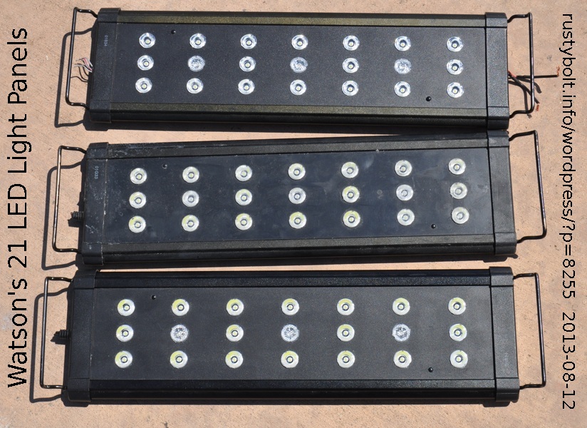
DSC_0465S3I went to my computer club meeting this Sunday and they had a really good deal on the consignment table that I just couldn’t pass up: three 21 LED panels for five bucks apiece.  They’re built very sturdy, with a body of extruded aluminum and screws holding the end covers in place. The ‘handles’ on the ends slide out to adjust to different widths, and the logo says Marineland, which leads me to believe that they might have been used for aquarium lights. Gee, how about that?  I guessed right.  I did a Google search and guess what I found!

The cables have been cut off, but I took one end cover off and I can access the wiring inside and splice a new cable on to it and put some heat shrink sleeve on the joint, and then put the end panel back on and no one will know the diff.  One guy said he used one with a 12V adapter, so apparently the panels run on 12VDC.  I just wish I had more info.  One panel has a display and push buttons on the end, so I think it has a microcontroller and dimmer circuit inside (I looked inside when I had the end cover off and the PC board has a few chips).  I think that they were all joined together and one panel was the master.  In any case, I have a whole lot of spare LEDs, most likely 1 watt, with the lenses to go with them, if I want to cannibalize one of the panels.  Cool!

Update Aug 19

I removed the end caps and found that if I pulled out the two plastic ‘bumps’ or studs, and then if I removed all of the lenses, I could slide the front plastic panel out and work on the circuit boards freely.

I traced the circuits out on the big LED circuit board and found out the following information.

All of the components are surface mount.

The LED board is made up of seven identical circuits, each with three LEDs in series.  There are six white LED circuits and one blue LED circuit.

The uppermost of the three LEDs has its anode connected to positive.  The cathode of the bottom LED is connected to the collector of a “D882” power transistor.

The emitter of this transistor is connected to two very low value resistors connected in series.  These resistors are “R620” or 0.62 ohm, and “1R2” or 1.2 ohms.  The other end of the resistors is connected to negative.

The emitter of this D882 transistor is connected to the base of a smaller transistor.  The emitter of the smaller transistor is connected to negative.  The collector of the smaller transistor is connected to the base of the D882, and both of these are connected to a “362” or 3600 ohm resistor.  The other end of this resistor is connected to positive.

The current to turn on the D882 comes from positive through the 3600 ohm resistor.  When the amplified current through the D882 and through the two low value resistors gets up to 0.35 Amp, the voltage drop across these low value resistors rises to 0.63V.  This voltage is also across the base to emitter of the smaller transistor and it turns on, and shunts away the current from the base of the D882.  This turns off the D882 and no more current can pass through it.  In effect, this limits the LED current to 0.35 amps.  That is about the maximum current for a 1 watt LED.

The circuit board is screwed down to the aluminum body which acts as a heat sink.  There is a large amount of white heatsink goop between the board and the body, so if you take all the screws loose, you will a very messy white circuit board and body that will get all over everything.  It is best to leave the board screwed to the body.

default

2013-08-10 Very Low Power Joule Thief Update

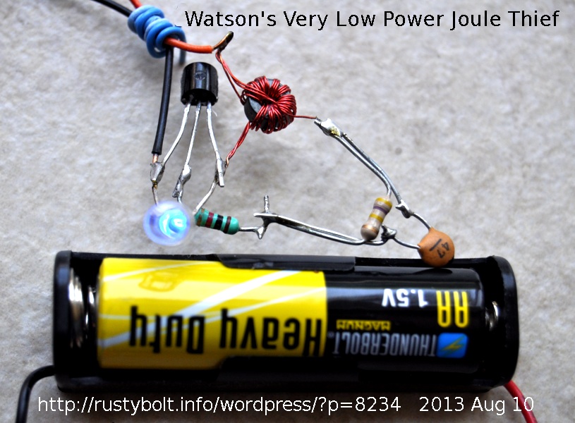
DSC_0464S3I blogged my experiments with this very low power JT back in April, and I connected it to a cheap ‘heavy duty’ AA cell and left it running for a month or two.  I added updates to the end of that blog I made one mistake: I should have taped a post it note to the AA cell with the starting date and followup dates and measurements.

As can be seen in the photo it’s still running – the LED is still lit – but the cell voltage is down to 0.9V.  These ‘heavy duty’ cells have a lot less (about half – see here) capacity than the alkaline cells, and the shorter run time and lower voltage seem to show this.  This just makes it easier to do tests because I have to wait half as long for the cell to run down (grin).  Thus I can say that the run time on an alkaline cell will be about twice the time it runs on a ‘heavy duty’ cell.

On the right can be seen the 470k resistor with the tan colored 47 pF disk capacitor across it.  This is the very high value resistor that throttles down the transistor’s base current to a very low value, causing the Joule Thief to run at much less than a milliamp through the LED, and greatly extending the AA cell’s life.  The AA cell has to supply less than a milliamp, too, something around a third of a milliamp, if I remember correctly.


default

2013-08-09 Free Energy Devices Powered By Protonic Reversal

Ah-HAH!  I found out what the ‘stuff’ is that powers the free energy devices.  All this time, no one suspected.  I think it has something to do with thermonuclear confusion.

http://uncyclopedia.wikia.com/wiki/Protonic_Reversal

default

2013-08-08 EMP Blog Uses Watson’s Supercharged JT

I came across this guy’s EMP blog describing his experiments with various Joule Thiefs, and the results he got.  I couldn’t find an email address or how to contact him, so right now I just have to say it in my blog.  He has been methodical and taken measurements while he has experimented and he shows the graphs of his results.

He has done some research, and viewed some Joule Thief info online, one of them was my blog.  I’m proud to say that he thought highly of my Supercharged Joule Thief.  But I was concerned  that he might damage something when he said that the transistor was overheating when he used three cells: the battery voltage was higher than the LED voltage.

When experimenting with Joule Thiefs, there are a few things that are important to remember.  One is that the LED is connected almost directly to the battery.  The resistance of the coil’s primary winding is very low, less than 1 ohm typically.  One end is connected to the battery, the other end to the LED, so it is almost the same as a direct connection to the battery.  The blue or white LED’s forward voltage is about 3.2 volts.   If the battery voltage is increased to 3V, the LED will start conducting, even with  the transistor disconnected.  This means the battery voltage is too high.

Two fresh alkaline cells in series will give 3.1 to 3.2 volts, which will light the LED very brightly.  Two used alkaline cells at 1.4V each will give about 2.8V, which should light the LED dimly, and may work okay.  Or two NiMH or NiCd rechargeable cells at 1.4V maximum each will give 2.8V or less, and should work okay.  If the LED still lights when the base of the transistor is disconnected, then the voltage is probably too high.

Another item that is important is the maximum negative voltage on the base, which is 5V or 6V  for most silicon transistors.  The emitter to base junction of most silicon transistors will start to break down at about 7 to 10V, and acts like a Zener diode.  But this permanently damages the transistor, the current gain will be permanently lowered.

Also, as the higher voltage causes current to flow in the LED, the LED’s resistance goes down, which loads the rest of the circuit, and prevents the transistor from switching on and off.  Instead, the current through the1k resistor just turns the transistor on and it gets hot from excessive current.

Emitter To Base Breakdown

The voltage across the feedback (base) winding is the same as the voltage across the primary (collector) winding, but it is negative, and the battery voltage, typically 1.5V, is subtracted from it.  So if there are  two LEDs in series, the total peak voltage across them is typically 4 to 4.5 volts each, or a total of 8 to 9V.  Subtract 1.5V, and it’s 6.5 to 7.5 volts.  This is more than the 5 to 6V maximum rating, and may damage the transistor.

This indicates that it’s a bad idea to put two or more LED in series; instead the LEDs should be put in parallel.  If the LEDs must be put in series, then the number of turns on the feedback winding should be reduced.  Half as many turns means half the voltage.


default

2013-08-06 7 Year Joule Thief

This Youtube video of a 7 Year Joule Thief from Xee2 AKA Xee2vids is similar to my low power Joule Thief I recently blogged.  I recently built this very low power Joule Thief.  The notes in the video were difficult to read, but this is what I could make out.

Notes:

1 – 1″ diameter toroid (Electronics Goldmine 5 for $1)

2 – Green LED is easily seen but not full brightness

3 – Needs capacitor but 100 pF works better than 0.01 uF.

4 – Frequency is about 10 kHz.

5 – Current, frequency and LED brightness are about the same if capacitor put in parallel with  resistor.

6 – Should light LED for over 7 years on 2000 mAh AA cell.  ( 2000 / .03 / 24 / 365 = 7.6 )

My comments on the notes on the schematic:

Regarding Note 1 –  The 5 for $1 toroids from Electronic Goldmine have been sold out for quite a while and since they were surplus, it is very unlikely that they will ever be back in stock.  I suggest that you try the toroids available from surplussales.com.  They have a range of toroids available, from less than fifty cents apiece.  I bought some of their ICH T231212T cores, which are only a very small 1/4 inch outside diameter.  But they will work fine for this low power JT.  The price is reasonable ($.25 apiece), and they say they still have a large quantity available.

Regarding Note 2 – The green LED is very visible to the normal eye because it is in the middle of the color spectrum.  Remember that the total input power to this circuit is 1.5V multiplied by 0.00003 amp, which is 0.000045 watt or 45 millionths of a watt.  That is extremely low power, and it’s amazing that your eye can see the LED lit up with such low power.  It is best to use a super bright LED and one that is easier to see, such as green, yellow or aqua color.

Regarding Note 3 -I put a variable capacitor in the circuit and tuned it for the maximum brightness.  The peak was very broad, so I used a 47 pF capacitor.  But the resistor was less than 2 Megs, and each circuit will probably take a different value of capacitor depending on the coil, transistor, resistor and LED.  In this case, 100 pF is a good choice.

Regarding Note 4 – As with the capacitor, the frequency will vary depending on the coil, transistor, resistor and LED.  Mine was 29 kHz, but 10 kHz (in the video) is a reasonable value.

Regarding Note 5 – I put the capacitor in parallel with the resistor.  But (as shown in the video) connecting one end to negative should not make any difference to the circuit.

Regarding note 6 – The AA cell will probably lose some of its capacity over the years just from old age.  But one thing Joule Thiefs have is that as the cell voltage drops, the current is reduced, which extends the run time.  One thing is certain: no one is going to wait 7 years to find out!

About the transistor

I used the BC337-25, which is a very good transistor for a full power Joule Thief, and capable of handling more current than the MPSA06 in the video.  However, this JT is only using a third of a milliamp, so the transistor is not being pushed to its limits.  I think even the lowly 2N3904 or BC547 would work okay in this circuit.  What we are looking for is good current gain at very low currents.  If you change the transistor, it might change the brightness and/or current consumption, so check to see if your circuit is okay with both.

Update Aug 9 – I wound a Goldmine “5 for $1” toroid with 20 turns and measured the inductance.  It was 5.95 millihenrys, high for the typical Joule Thief (typically .5 mH or less), but it’s not an issue with this low power JT.

Back to experimenting…

© RustyBolt.Info/wordpress
CyberChimps