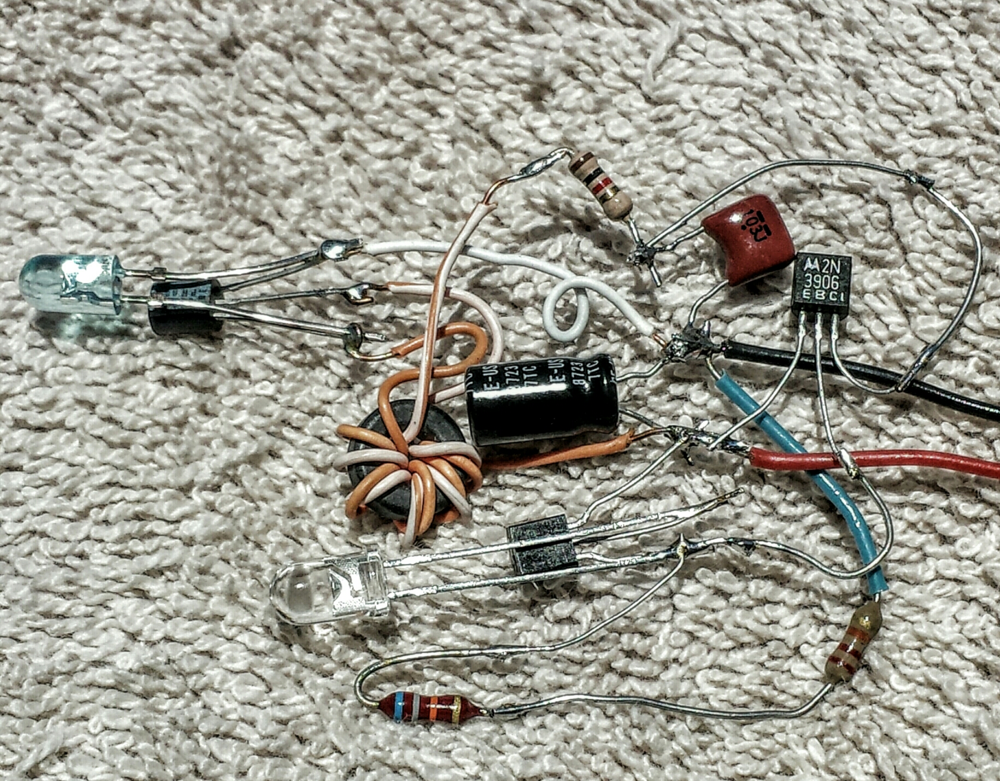
I designed my Blue Blinky with a daylight shutoff, using a LED as the light sensor and an additional transistor to amplify the minuscule current that the LED puts out. This worked just great because there is the point across the timing capacitor where the current is very low, and it takes very little current to shut off.
With the continuously on Joule Thief, the bias current to the base goes through the 1k resistor, which is about 0.9 mA, which is a lot more than the Blue Blinky. Therefore the current is much greater and the LED and transistor must be amplified much more. This is done by Q2, a PNP 2N3906.

The Joule Thief is center and left. The light sensing LED is at bottom center along with the 2N3904 to amplify its current. Black and red wires are minus and plus 1.5 volts respectively.
I experimented with the resistance from the 2N3906 base to negative and found that this resistor controls how sensitive the LED is to light. It also controls how bright the output LED is. I’ll have more on this in the note at the end. The 2N3906 is supposed to switch fully on or off depending on how much light there is. But it needs enough current from the 22k and 68k to turn fully on. At the bottom of the schematic I show two resistors, a 22k and a 68k in series for 90k total. This was a guesstimate, so I put a 100k trimpot where the 68k is, and found a higher sensitivity when the two resistors were higher, around 100k. But I found that when I turned the pot to minimum resistance the LED got brighter. The problem seems to be that when the resistance is adjusted for good sensitivity, the 2N3906’s base is not getting enough current to fully turn on. What I need is a much higher gain PNP transistor that requires much less current to turn fully on.
So I then unsoldered the trimpot, and replaced it with a 47k resistor, for a total of 47k + 22k = 69k. This seemed to be a good compromise between brightness and sensitivity, but it’s still a compromise. I then replaced the 2N3906 with a PNP that has higher current gain, a BC560C, which is the same as a BC557C. The circuit now is more sensitive to light and the LED comes on bright. Also, I did the work on this in a room with closed blinds on the windows so the light was not bright. If the circuit is taken outside there is plenty of daylight to turn the circuit fully off, and nighttime is dark enough to turn it fully on.
Note – The transistors have current gain that is influenced by their design, manufacture, and temperature, and from one transistor to another may vary over a wide range. I used transistors that are moderate gain, and if the next one I choose happens to be lower gain and it happens to be cold then the light may be very dim. So it’s important to design the circuit so that the transistors be high enough gain so they do not influence the circuit’s performance.
I also notice that the light sensing LED is directional, because the LED’s lens focuses the light from straight ahead onto the chip. The lens could be sanded flat to let more light in.


I like seeing circuits like this.
I m not able to design circuitry, so this is interesting.