


I ordered these clock kits a few weeks ago and they finally arrived today. I just couldn’t keep my hands off the soldering iron, so I started stuffing the board with components. I was blindly winging it because the instructions that came with it were in Chinese. I didn’t have any problems because all the component values were marked on the single sided PC board. The one thing that might be confusing to the inexperienced assembler was the resistors were 1 percent and have more color bands, but he or she can use a DMM to measure and find their values. There are only three different values: 470, 4.7k and 10k.
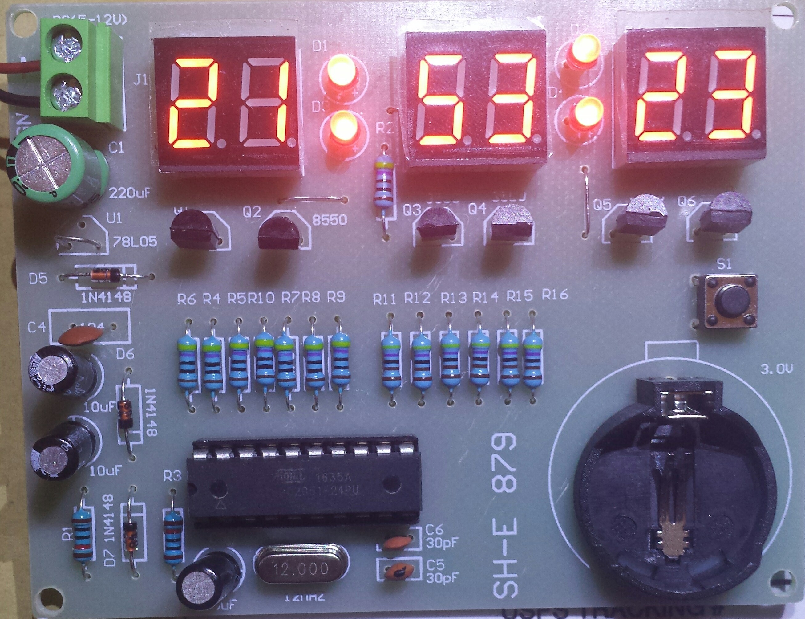
Most of the other parts were polarized and the assembler must take care to put them in correctly. For me that was not difficult due to the markings on the PC board. The four red LEDs were 3mm and it was a bit harder to see the markings and stuff them in correctly. The switch pins didn’t align with the holes so I had to bend them a bit. When I opened the bag of parts (on both clock kits) the coin cell holder was missing a pin, and it had fallen out into the pile of other parts. It was a bit of a problem to get it to seat correctly when soldered.
I soldered in the 20 pin IC socket, then I had to bend the Atmel microcontroller chip’s pins to get them to align with the socket pins before it would seat into the socket. All these minor problems are typical for the assembly of any PC board.
I didn’t install the 78L05 regulator because I plan on powering these clocks with a 5 volt AC adapter ‘wall wart’. The board says 5 to 12 volts next to the connector, but the 78L05 needs a few volts difference between input and output to stay in regulation. That means the input should be at least 7 volts, preferably 8 or 9 volts to be safe. For now, I put a jumper wire between the input and output of the 78L05.
This kit should make a good project for a kit builder who already has some kit building experience. There are no surface mounted parts, so soldering is not difficult. And for just a few dollars, the kit builder can get a project that can be used around the house in many locations.
Since I couldn’t read the instructions, I had to guess how to press the single button to set the time. I couldn’t figure out how to change the display from 24 hour to 12 hour format. It may be the clock has no way to change to the 12 hour format. It would be nice if I could get the Chinese translated. I watched a review of a similar but not the same clock on YouTube, and it had three buttons. It had other functions, might’ve had an alarm. This clock seems to have had as many features removed as possible to make it cheaper. One corner they cut is the four colon LEDs. On the other kit on YouTube the colon LEDs blink every second. My clock doesn’t blink at all. And apparently in order to save one resistor, the current for all four colon LEDs in series/parallel goes through a single 470 ohm resistor. I would have been nice if each colon had its own resistor. That way, the kit builder could use different color LEDs without having problems getting them all to light.
I’m in the process of assembling the second PCB. I have to look around to find the bag of coin cells that I got when I bought several red lasers from Electronic Goldmine. They periodically put the red lasers on sale. Update: I watched a video on YouTube where the assembler didn’t use the coin cell. Apparently the coin cell has to power the whole circuit including the display when the power is out (the schematic showed this). He said that the coin cell can’t power it for long and quickly runs down. So instead of using a coin cell, he used a few AAA cells. So what I’ll do is remove the coin cell holder and solder two wires, and put a three AAA cell holder (from a 9 LED flashlight) in its place.
Right now, I need the battery backup more than ever. Over the last month my other clocks in my house have gone into the reset mode after power failures. These outages may only last a few seconds, but they are enough to cause my clocks to reset. For months previously there had been no power outage problems, only recently have there been several short outages. I’m hoping they will stop and reliability will return.
Here is a review of this clock on Youtube. He said he paid less than $8.00 for two kits. He says there is no way to convert the clock to 12 hour format, the clock displays only 24 hour format. Judging from my experience, I believe he is right.
Update May 31 – I removed the coin cell holder and connected up a four rechargeable NiMH pack. I changed the 10k resistor across the diode to a 100 ohm, 1 watt resistor. This allows more current to flow backwards from the power supply into the NiMH pack to keep it ccharged. The voltage across this resistor is less than 1 diode forward voltage drop, so the current is only about 5 mA. I forgot to accurately measure the power supply current but it’s less than 100 mA.


