default

2017-05-29 M-6013 Capacitor ESR Meter -Not

Several weeks ago I purchased a “M-6013 Capacitor Meter ESR Meter” from a Chinese seller on eBay.  It cost about $27, and I think shipping was 99 cents.  I received it two weeks ago and read all the instructions and tried all the buttons and functions, but I found nothing having the ESR test.

I put the meter back in the box and shipping bag, thinking that I would have to return it for a refund.  It was very clear to me that the seller was falsely advertising the meter’s capabilities, and something must be done to prevent this seller from taking advantage of other customers in the future.

I started an eBay resolution complaint, which sent the message to the seller.  After a few days, they sent a reply saying they were sorry, and offered me $8.00 refund.  I thought it was a fair offer, but the seller would still not be prevented from taking advantage of other customers.  So I replied that I couldn’t use the meter without the ESR capability.  I was hoping that the seller would offer a full refund.  Also, eBay requires that the buyer wait several days until he/she can take the next step if they are not satisfied with the seller’s offer.

The seller then asked for pictures or video to explain the problem.  I thought that the seller was trying to make it more difficult for me to resolve this complaint.  The seller didn’t want to issue the full refund, and the number of days had passed, which now allowed me to escalate the complaint to the next level by sending the message to the eBay mediators.

So I sent the message to mediation, saying that seller advertised the meter as an ESR meter but I couldn’t find anything in the instructions or any function on the meter for ESR.  I said that the seller had asked for pictures, but that I can’t take a picture of something that the meter doesn’t have.  I sent it off, hoping for the best, but expecting more excuses from the seller.

A few days later I received a notification.  It said that the seller had refunded my $27 and shipping, and I was relieved that I had received my money back.  But I am still concerned about how many other buyers will be deceived into buying this meter that doesn’t do what it’s advertised.  How many other customers will start a complaint resolution, and be satisfied with the $8 offer, and be stuck with a meter that can’t do what they bought it for?  How many more meters will the seller sell before the buyers’ complaints make him quit falsely advertising?

I got my money back, but the price I paid was getting the complaint resolved without giving the seller a negative feedback rating.  There was no feedback to warn future customers that the seller was falsely advertising this meter. 

I want to make a comparison between this complaint and the problem I had last month with an Amazon seller.  I bought a drill and an accessory, a chuck and chuck key.  When I received the package, it wasn’t opened, but it was obvious that something had gone through the shipping tape.  I found that the chuck and key had been attached to the display card by zip ties, and the chuck had slipped out of the zip tie and was not in the package.  So I started Amazon’s complaint resolution process.  I went through the menues, and they didn’t have a choice that described the missing part, so I had to choose one for broken.  Also, the description allowed me to type only a few lines of text, not enough to give a comprehensive description.

Then the procedure required me to pack the item in a package for return.  The app issued me a return code, like a bar code, and told me that I had to take the package to a UPS store and show them the code on my cell phone and they would put a sticker on the package and ship it back to Amazon.

I did all this, and in a week or so I received a replacement chuck and key.  But it cost me the money for the package and time to wrap it and take it to UPS.  And it cost Amazon the return shipping costs and processing costs.  But what I liked was that Amazon and seller both got feedback on what the problem was, and how to prevent it in the future.  This feedback is very important because it will help avoid the problem for both the customer and Amazon in the future.

default

2017-05-27 Oscillator, AM BCB

Uncategorized

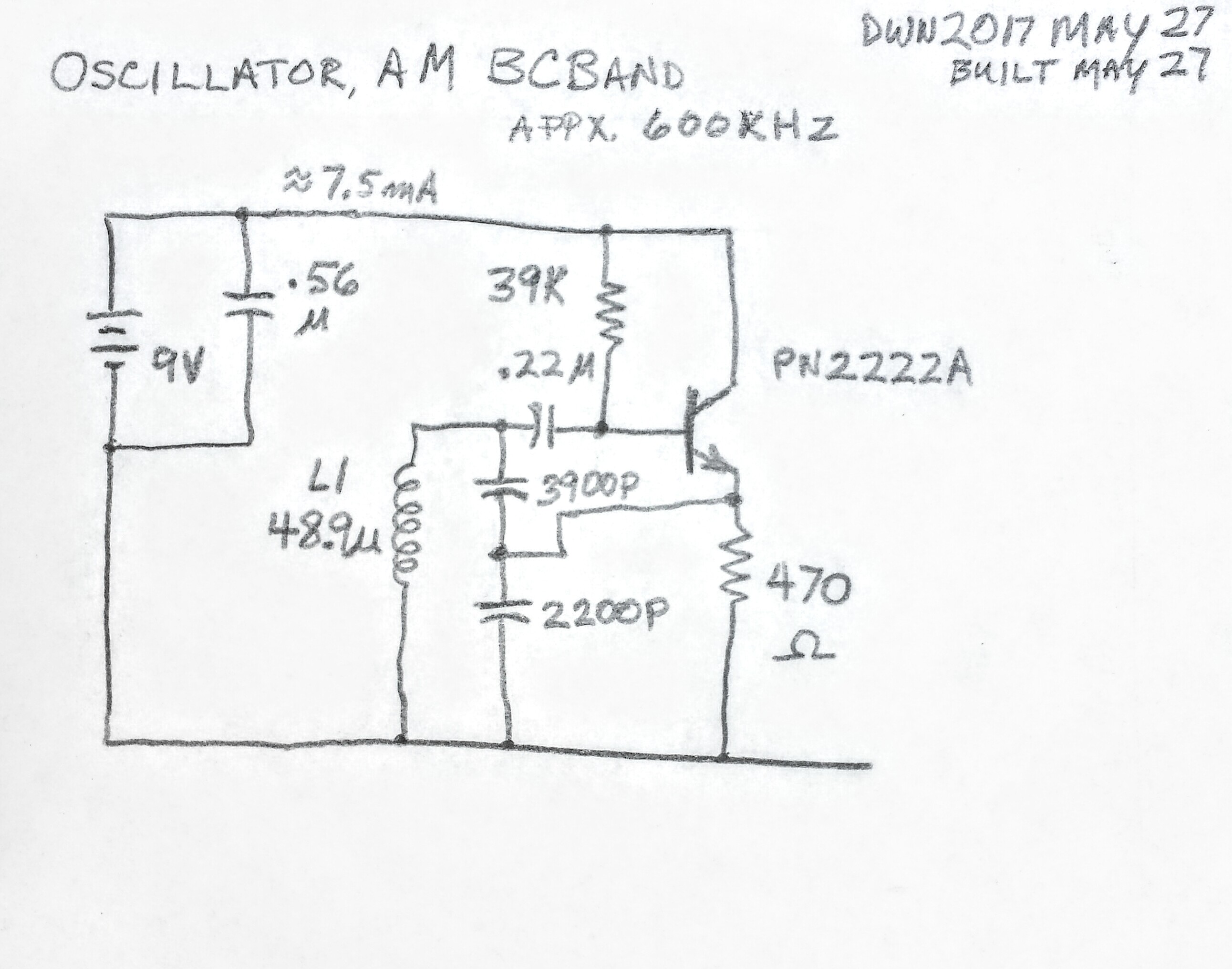
I built this Oscillator to see how far a small loop of wire can radiate the RF.  I’m not using an antenna, just the radiation from the coil.  The coil is about 15 feet of solid insulated telephone wire jumble wound on a pill bottle with a diameter of 50mm or slightly less than 2 inches.  The width of the coil is less than 20 mm or about 3/4 inch.  It measured about 49 uH.  I used a 3.9 nF and 2.2 nF in series, which gives 1407 pF.  This and the 49 uH coil resonate at about 600 kHz, on the lower end of the AM broadcast band.

The 470 ohm emitter load resistor lets a lot of current flow, over 7 mA.  A 9 volt battery won’t last very long.  I thought about using a 1k, but I wanted to try to see if the extra power gives extra range.  I may change it later.

I put it on the interrupter that I built earlier (see blog of May 4) and to a 9 volt power supply.

I’m going to walk around with a portable AM radio to see how far the signal is radiating.  There is so much man-made interference at these frequencies that it’s difficult to receive the AM radio stations.  I usually get a lot better results with FM transmitters.

After a short walk, I found that I could barely hear the signal outside of the house.  The signal is very weak inside the house, and just 5 meters or 16 feet is all it can go before disappearing in the man-made noise.  I may try a larger coil, but the coil is the part of the circuit that takes the most time to build.  I think that the signal might  go a little further if I put an antenna on it.  The problem is the rules allow the antenna to be no longer than 3 meters, so it won’t help much.

default

2017-05-26 (Not A) Wien Bridge Oscillator 

Oops!  (posted to FB groups)

​A Wien Bridge Oscillator that’s not a bridge.  It’s missing the negative feedback side of the bridge!  That must mean that the amplitude of the sine wave changes with changes  in the temperature, supply voltage, and other conditions.  Not a good design!

http://www.seekic.com/circuit_diagram/Signal_Processing/Oscillator_Circuit/WIEN_BRIDGE_OSCILLATOR_I.html

default

2017-05-25 I Buy Parts From…

From a comment in FB group

I buy most stuff from Mouser because I found their prices are lower than Digikey.  I’ve had bad experiences with mouser, mostly shortages on quantity, but I had some disc caps thar were below tolerance.  Mouser has some cool ways to narrow down the selection to a manageable size.  But I can’t understand why some parts don’t show online but show up in a page of their catalog.

But Newark Element14 has some good deals, too.  I can’t figure out what goes on with them because some parts come from multiple places.  And Arrow has had free shipping, depending on things, and some parts come from a company called Verical, apparently a subsidiary.

I bought stuff on eBay and found the prices were fair for quantities below 100, but the sellers are sorely lacking on specifications.  Lots of things can’t be told by pictures, but you can always message the seller and ask.  I’ve had more bad experiences with eBay than anywhere else.  But then I’ve bought a lot of items from a lot of sellers.

I had one bad experience with Alibaba, but it was my first, and will be my last for a few years until they mature to the point where eBay is today. 

I’ve bought a lot of stuff from Amazon, but they have so many sellers it’s hard to tell who’s selling what.  Prices are higher, but you get better service.  What I dislike is Amazon won’t accept PayPal.   I think Amazon was better years ago when they were trying to gain market share.  They offered free shipping for $25 minimum, it went up to $35, now it’s $45, or whatever.  I just had to use their return service recently, and I think their  menus were not user friendly.

And I’ve bought stuff from other online stores, and found that it pays to shop around.

default

2017-05-24 DECWriter LA-36

From a comment I posted to FB Vintage Test Equipment group.

I’m looking for some parts for a DEC DECWriter LA-36.  The model I have has the acoustic modem behind the paper feed.  I’m also interested in other parts.  If there are others who have this big, heavy printer, I also have some manuals for it, such the IPB (illustrated parts breakdown).

default

2017-05-21 22-120 Power Schematic Errors

Posted to FB group 2017 June 8, then a copy here.

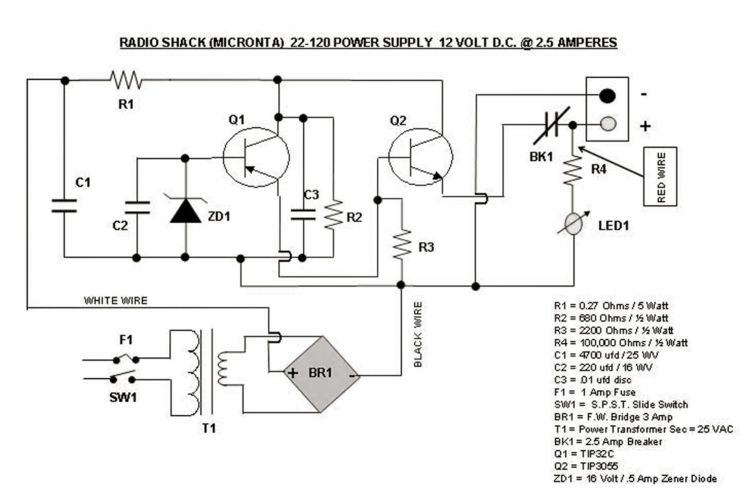
I found this Radio Shack power supply on Bama.edebris.com.  Looks like someone drew it up.  I found a few boo-boos, one being the LED having a 100k current limiting resistor.  It’s not going to be bright.

I wonder if BK1 thermal breaker is capable of interrupting  the current before the transistor(s) burn out.  BK1 also causes a voltage drop so it contributes to poor regulation.

The drawing is somewhat confusing.  R2 and C3 should be to the left of Q1.  etc…

I also noticed that it says the T1 secondary is 25 volts.  That means Q2 will have to dissipate an excessive amount of power in order to supply 2.5 amps.  It also means C1 will have a lot more than its rated 25VDC, and will probably self destruct.

It looks to me like the Q1 PNP is bass ackwards, so I don’t think this schematic is ready for prime time.

default

2017-05-20 Telephone Line Kicker Meter

From a 2017-06-10 comment regarding a Weston capacitance meter on FB group vintage test equipment 

Reminds me of the ” kicker” meters the phone techs used on the phone lines.  There was a polarity switch that reversed the pair, and the tech could tell about the line from the kick the meter needle gave when the polarity was reversed.  The capacitance and hence the charging current depends on the length of the line.  If the tech knows the line is ten thousand feet long, it’ll kick more than one that’s only 2 kFt.  Or if one conductor to ground kicks less than the other, that conductor may have an open along its length.  Or it might show constant meter current, indicating leakage.  The meter used quite a bit of voltage, 45 volts or so.

All the thousands of lines on my campus were under a few thousand feet, so it didn’t kick much at all.  But just for grins, I punched down several jumpers on both ends of a 1200 foot cable, until I had a line probably 2 or 3 miles long.  The signal just looped back and forth between the two ends, until it came out right near where it started.  I was sort of like the phone phreaks, who would call themselves from all the way around the world just to hear the delay.  The cable I was using had more than a thousand pairs, hundreds weren’t being used, so I could have made a pair that was a dozen or more miles long.  But long before that, the losses would have been so high that the signal would be very weak by the time it returned to me.  But it was fun trying.  😉

default

2017-05-17 Lamp In Audio Oscillator

This is from a FB comment by me.

Speaking of audio signal generators, I made an audio signal generator, the classic Wien Bridge oscillator with the lamp, in my case it was a 28 volt low current lamp, I believe an 1869.  Well I got the lamps from Radio Shack, and the circuit had an intermittent problem.  I tried more than one lamp before I found a good one.  The end of the tungsten filament is held between the lead which is folded over on itself and then squeezed closed.  There is no weld, probably because tungsten is very difficult to work with.  Apparently the leads were not closed tightly on the filament end, which doesn’t show when the lamp is tested at full brightness.  But at lower temperatures, the leads are loose and make intermittent contact.

Once I got that problem fixed, the oscillator put out a clean sine wave.  My circuit used three transistors.  

default

2017-05-09 

At work I had a Fluke 8040(?) that had the LCD tilted up.  Worked great, but after a half dozen years we had so many terminals in (and out of) service that I couldn’t spend as much time troubleshooting, and since Lear Siegler was less than a dozen miles away, we just bought enough spares as replacements for the ones out of service and being repaired.  Things weren’t so bad when there were only a hundred and twenty, but when the administrators saw productivity was much better, they all wanted them for their department.  So a couple hundred grew into 3 or 4 hundred.  And then the Apples and IBM PCs came on the scene…

The original Lear Siegler terminals had a CRT assembly made by Ball Bros, a good reliable CRT.  But to save money, Lear Siegler replaced them with cheaper CRTs from this foreign company that I’d never heard of.  And then when the Lear Siegler terminals went on the fritz, a column of smoke came out of the vents on top.  This was very alarming to the users, but it was only a five cent resistor, in series with the DC power, that burned up.  So instead of a resistor, I replaced it with a 1/4 amp fuse.  It solved the problem, but I wondered why this unknown Korean company, Samsung, didn’t put a fuse in their CRTs.

default

2017-05-05 27 Mhz Signal Generator Continued

 This continues the updates from my blog of 2017-04-21.

Last night was the fifth of May, and I made several important changes to the circuit.  I was finding that after adjusting the 8 to 50 pF N150 ceramic variable capacitor, the frequency would drift for hours, then overnight the drift would settle down to a low level, until I adjusted the capacitor again.  I think this capacitor may be wearing out, so I removed it.

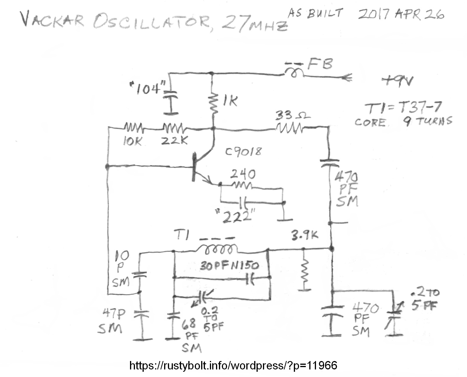
I put two capacitors in series to get the frequency back down but these were only 18 pF, so I removed one turn from the core, leaving 9 turns.  I then changed the parallel capacitors to get the frequency down to 27.145 MHz.  I also added a 0.2 to 5 pF variable capacitor in parallel to give a small amount of adjustment.  Once I adjusted it to the correct frequency, the drift was much less than before, the oscillator stayed on the correct frequency overnight.  Now this Vackar oscillator is doing what Vackar oscillators are supposed to do: be very stable and not drift and stay on  frequency.

It’s May 6 and I left the oscillator running on the shelf all day.  The frequency has been very stable as long as I don’t move it or put something near it.  I think it has drifted only a few hundred hertz since yesterday.  Once I got rid of that 8 to 50 pF ceramic variable capacitor, it has been solid as a rock.  It’s hard to believe how much difference the right capacitors make.  

I wound another T37-7 core with 9 turns of solid PVC insulated telephone wire and measured it at 350 nH, but cores may vary by as much as 20% from core to core.  I can say that the one in the oscillator is under 400 nH.  

The circuit needs to be built on a PC board with a ground plane to provide shielding.  Also it should have a varicap and potentiometer to adjust the frequency.  The whole circuit should be in a metal case.  It might be okay to put it inside an Altoids tin.  Also a buffer stage should be added so the oscillator will be isolated from external influences.  The buffer stage should be Amplitude modulated so it can be heard on the receiver.

This afternoon I was reading about Vackar oscillators and I found different documents with somewhat different parts values and ratios.  The circuit is a type of Colpitts oscillator, it’s just the capacitors and their values that are different.  All I have to say is the circuit is tolerant of my experimenting and is well behaved.  Now if only I could get my regenerative receivers to work, so I can receive what the oscillator is putting out.

Update May 13 – I left the circuit running on the shelf for most of the week, and it has drifted upwards a few kHz during that time.  Not any fast changes, just a slow movement upwards, possibly due to temperature change.  This is long term, so if I used it over a period of a few hours, the drift would be less than a hundred Hz.

One problem that this has is it’s sensitive to handling, so making changes to the trimmer capacitors takes a lot of trial and error.  I could put the varicap back on it, but I’ve read that it can cause some problems.  But it has the advantage that I can run a few feet of wire from the circuit to a pot, so I can adjust the frequency without coming near the circuit.  I also thought about adding a thermistor to the pot to correct for temperature changes.  But I don’t think it really needs it.  What I need is to amplitude modulate the carrier with a tone so I can use it for experimenting on the regen receivers.

Update May 20 – I made several important changes to the circuit.

I changed the capacitor connected to the 33 ohm resistor from 470 pF to 1000 pF.  This is a DC blocking capacitor and has very little effect on the frequency.

Removed the 30 pF N150 and 5 pF variable from across the coil.  There are no more capacitors in parallel with the toroid coil. 

I changed the 68 pF SM to 100 C0G.  

I put the 30 pF N150 in parallel with the 470 pF on right side of the coil.

The frequency was still too high so I added two of the 0.2 to 5 pF from the left side of the coil to ground.  One is at max 5 pF, the other is part way.

I calculated the effective capacitance of the parallel tuned circuit and found the left side of the coil has appx 118 pF.  The right side of the coil has appx 502 pF.  The equivalent capacitance across the coil is 94.4 pF, the frequency is 27.145 MHz, and the XL = XC = 62 ohms.  The coil calculated to be 364 nH, which agrees with measurements.

© RustyBolt.Info/wordpress
CyberChimps