default

2012-02-19 Audio Compressor

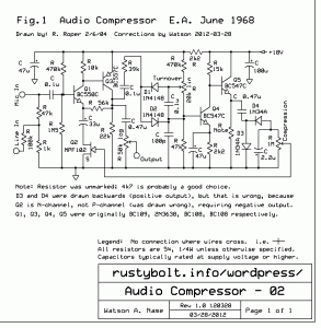
See my General note at the bottom for some info on audio compressors in general. I had this hand drawn schematic in my SCH files folder, dated from 8 years ago.  The actual schematic was from “E.A.” dated 1968.  I can’t figure out what E.A. is.  I would imagine that the E stands for electronics, but I don’t know about the A.  I found a few mistakes and omissions, so I updated the hand drawn schematic.  Then I decided that the schematic would look much better if it were drawn in ExpressSCH, so I did that.  Took me quite a few TV commercial breaks to get through it all.

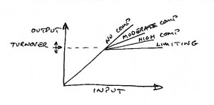
Basically it’s an audio amplifier with a variable resistance FET in series with the emitter bypass capacitor.  This reduces the gain when the FET is biased with a reverse voltage.  There are adjustment pots for the amount of compression and for the turnover point where compression starts to take effect.  For more, check out the schematic and graph photo.

Update May 19   So far, I’ve had two comments from others on it (click on the pic 2 or 3 times to see comments). One comment mentioned that this circuit originally used germanium transistors, which makes sense since it is dated 1968.  The others and I have redrawn it with silicon transistors, but I have not checked to see if the resistors have been changed to what they should be for silicon.  It may be that if it’s built as shown, the values may be off enough to cause problems.

The two transistor microphone amplifier stage has a gain that depends on the ratio of the 56k resistor and the internal resistance of the MPF102 JFET.   One bad thing about JFETs and especially the MPF102 is they have a wide variation in the internal resistance; in the case of the MPF102, it’s ten to one.  So if you just put any MPF102 into the circuit, you may get a wide variation in performance.  The way to avoid this is to select a MPF102 with a higher IDSS.  A higher current means lower internal resistance.  The amplifier will then have a greater range between the maximum and minimum gains.

Another way is to put more than one JFET in parallel.  In this circuit you can put 2, 4 or more JFETs in parallel to decrease the total internal resistance.  With more than 1 FET, I would change the 1 Meg compression adjustment pot to a lower value, such as 500k or maybe less.

Another way is to use a JFET that has much lower internal resistance.  I think the J105 may be used for this purpose.  Instead of using a JFET, it’s possible to use a MOSFET such as the 2N7000, which has an internal resistance of 5 ohms.  But since it is an enhancement mode FET, it must be biased to be turned on by a resistor or two.  The required voltage is between 0.8 and 2.4 volts.

The 56k resistor may also be modified to get better compression or range.

Update May 20 – I’d like to thank Darren for sending me the original schematic.  As he said, it used a 2N4360 P-channel JFET, which is the opposite polarity compared to the MPF102.  The output of the rectifiers and filter cap is positive, which then goes through the 1 meg pot and then to the gate of the JFET.

Update May 24 Further information about other compressors – I had a schematic of a battery operated cassette recorder.  The way the microphone signal was compressed was with a regular transistor, not a FET (I’ll call it the BJT).  The emitter of the BJT was connected to ground.  The base was connected to the rectified and filtered DC from the output of the preamplifier.  The higher the microphone level, the more current was sent into the BJT’s base.  Then I was puzzled as to why the BJT’s collector was connected directly to the microphone.  But that’s how it worked.  The more current that went into the base caused the BJT to have lower resistance between the collector and emitter.  The BJT was being used for a variable resistor to shunt more of the microphone’s signal to ground as it increased.   It worked fairly well; the microphone signal was compressed to prevent overloading the microphone preamp.

This same technique can be applied with a JFET or MOSFET.  The drain and source of the FET are connected across the microphone.  A loud microphone signal causes the greater voltage at the gate to turn on the FET and shunt the microphone signal.  The FET can have a very wide range of resistance, from millions of ohms to less than 5 ohms.

Another schematic of an audio compressor that uses an opamp.  Some of the output of the opamp is fed back to a red LED.  The light from the LED shines on a CdS photocell which is connected from the output to the inverting input,  The more light, the lower the CdS resistance, and the more negative feedback to the opamp, which reduces its gain.  The disadvantage of this is that the CdS photocell is slow to change its resistance, so the fast, loud signal may not be compressed quickly enough during the first fraction of a second.  That excessively loud signal may overload the opamp.

General – The compressors used in radio and television broadcasting are very expensive and are sophisticated, with bandpass filters that allow compression of a band of frequencies.  It would imply that a simpler compressor covering the whole audio band would therefore not do as good a job as these more expensive ones.  But with audio that varies greatly in loudness, something is needed to prevent overload of the amplifiers and audio equipment.  A simpler wide band compressor will achieve this and help prevent overload.


default

2012-02-18 Mystery Sensor

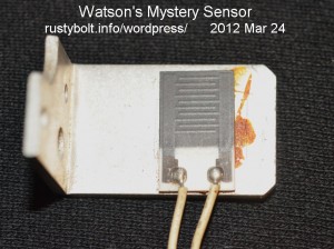
This came out of a box of junk that had accumulated for a long time in my garage.  So long a time that I’ve no recollection of what it is or where it came from.

I looked at it and thought that it was a temperature sensor because it was mounted on a bracket that could act as a heatsink. It looked similar to a CdS photocell, but light doesn’t affect it.  The black part is about a half inch or 12mm on each side.

I connected it to my DMM and it initially measures over 800 ohms, so I held my soldering iron under it until the heatsink became too hot to touch.  The resistance went down to 500 ohms, so I let it cool off, and it remained at a bit over 500 ohms.  What’s going on here?  If it was a temperature sensor, it would have gone back to about 800 ohms.

Puzzled, I pulled a strong magnet off the table and put it on the sensor, but it had no effect whatsoever.  However when I was handling it, the resistance went up somewhat.  I opened my mouth and breathed humid air on it, and the resistance shot up to 1200 ohms!  What is puzzling to me is that normally when something gets more moisture on it, the resistance goes down, not up.  In this case it was behaving just the opposite.

It puzzles me what kind of equipment would have a humidity sensor mounted on a heavy aluminum bracket that acts like a heatsink,  It looks like the sensor and bracket were made to be mounted inside of something; if they were mounted so they were exposed, they would have more protection against being harmed by their surroundings.

I welcome comments on what this is and where it came from.  Click on the picture to leave a comment.

default

2012-02-17 Credibility Regarding LEDs and Electronics

on February 17th, 2012 by - Comments Off on 2012-02-17 Credibility Regarding LEDs and Electronics

In the world of Electronics, as in the Real World, there are those who try to manipulate the truth to take advantage of those who have a limited understanding of its underlying principles.  We will call these manipulators scammers.

One scam that I often see is when an experimenter tries to get a LED circuit running and tells everyone that it’s brighter than before.  The presenter says that it’s brighter, but gives no quantitative measurement, only that it looks brighter.  Without a measurement, his brightness claim is nothing more than an opinion, with no basis in fact.  It is up ti the person making the claim to provide evidence that what he is claiming is true and more than just an opinion without any factual basis.

If a project has claims of a certain performance, then it is logical that the performance should be documented.  A measurement of light output of the LED would give a relative indication of performance.  Light meters, or luxmeters, are inexpensive, less than $50 with shipping.  Provided that the LED is kept the same distance from the sensor, the luxmeter will give a reasonably accurate indication of the light output of the LED as the circuit is adjusted.

Those who have little experience in this field should always remember that what people say and what the actual truth is have little relation to each other.  If someone makes a claim, the first thing that the viewer should ask is what is the claim based on?  Is it just a statement of opinion, with no evidence that is proof?  If so, then do not accept it as being true.

In this case of the claim that “it’s brighter”, the guesstimate is being made by the claimant’s eyes.  The eye can be very deceptive.  When the person is in a bright area, a fairly bright LED can look dim.  One good example is when you try to view your cell phone screen outside and it looks so dim you can barely read it.  You have to go inside to let your eyes open up so that more of the cell phone’s light gets in.  What this means is that your eye is a very poor judge of brightness because the pupil of your eye adjusts automatically and you have no indication of how it’s limiting the light.  In one bright area you would make a judgment that the LED is dim, but in a darker area you might judge the LED as bright.  So the Number 1 Rule is to never trust your eye’s judgment on how bright something is.

Parts – They’re important  Do you understand what your components are doing, and do you know if you are subjecting them to stresses outside of their rated limits?  If you are, do you have a way to test them to see if their performance is still normal?  A mountain climber doesn’t use a frayed rope.  But in the case of an electronic component, one may seldom see the effects of use and abuse.  If you don’t have a way to test them, then you should be stocking new and unused ones that have not yet been through the mill.  Transistors are cheap, only a few pennies apiece.  It’s foolish and futile to try to get a circuit working when a 4 cent transistor that has been abused is the problem causing the trouble.

I must say a word about the parts and their suppliers.

If you get parts from a reputable distributor you can be reasonably certain that the parts are new, prime parts without any “seconds” that may be out of tolerance.  If you buy from some distributors, you may not have a choice of selecting a better grade of component.  For instance, if you buy a BC337-25 transistor from Digi-Key or Mouser, you are ordering that exact transistor with the gain range of -25 specified.  If you order a BC337 from Futurlec, they may not have any gain range suffix, so you will not know what the gain of the transistors you receive are.  They could be evenly distributed throughout the gain ranges, which means you could measure the gain and select the higher ones for your use.  This could save you some small amount of money, but when Avnet charges $2.28 for a hundred BC337-40s, and Futurlec charges $7.00 for the plain BC337, it really makes no economic sense.

Surplus dealers are a whole ‘nother story and run the gamut from new, never used parts in their unopened packages, to cannibalized parts removed from old equipment.   The cannibalized parts at first seem to be the worst choice, but that may not be true, I’ll explain.  With cannibalized parts, you are not deceived: you know ahead of time that you’re getting used parts.  In some cases, the part may have a lifetime associated with its use so the older it is, the less life it may have left.  But if you can’t find it in better condition, this may be the only choice.  In other cases, when the part such as a transistor has been used within its rated maximums, can continue to be used with full performance and no degradation for decades to come.

On the other hand, there are those parts that may have made it through the production line, but my be out of tolerance or what they call ‘seconds’.  Here is a part that may look new, and may be sold as new, but is not capable of performing as a new part.  The new look allows the seller to deceive the buyer and get premium prices for an inferior part.  This often happens with electronic parts because the electrical and electronic qualities of the part may only be found with test equipment that the average buyer does not have.  Thus the average buyer may never know that he or she has bought substandard parts.

There is another category of parts that has been found, counterfeit parts.  With transistors, especially power transistors, the counterfeiter rubs off the original markings and puts on the markings of a higher performing power transistor.  The buyer gets stuck with a substandard part that may fail due to its inadequacy.  And you might think these don’t get into the mainstream market, but you could be wrong.  Some otherwise reputable distributors get stuck with these dud parts even when they believe they are getting prime parts.  But the chances are far less than if the buyer were to get the parts from a shady dealer.

All together, the parts that buyers receive can determine the fate of the product they go into.  If the experimenter buys a low grade part, it may not effect the outcome of the equipment as much.  Yhe experimenter may find that the part is not giving the performance that was expected.  A high volume producer may have hundreds or thousands of the product sold and in service when it is discovered that the product has defective parts.  This happened several years ago when, among other PC makers, Dell made GX-270 computers with electrolytic capacitors that were defective, and started to fail after a year or so.  It cost the company a lot of money – $300 million US – and hurt their reputation.

default

2012-02-16 Amplified Ear & Hearing Aid

I found this schematic of a hearing aid on a newer website called Talking Electronics, and it looked familiar.  I checked the one on RedCircuits.com, and found that they are identical, other than the copycat has gone to some lengths to pretty it up with color and graphics.  I know that this particular schematic has been around since before the website was called Red Circuits, because years ago I built this circuit and put it into an Altoids tin and I still have it today.  Either one or the other of these websites has stolen it from the other, and my bet is that Redcircuits had the original, because of what I just said.  I think I built the circuit long before the Talking Electronics was around.

default

2012-02-15 (watsonseblog) AC128 Germaniums

2011 Jul 05 AC128 Germaniums

I was looking on eBay for some germanium transistors that might have a better chance at being used for a Joule Thief. I blogged my Germanium Supercharged Joule Thief a few days ago and said I came to the conclusion that germaniums were a poor choice for a SJT. I still think the germanium transistors that are least uncommonly available are not a good choice. But I should have said that the common germaniums are typically made for small signal use, and not for higher current use.

Further explanation
When I did some comparisons I found that the germaniums were constrained a lot more than silicons, due to their inherent limitations. If I put a germanium power transistor, even a lower power one like the AD162, into a JT, it would not work at frequencies above the audio band, roughly 10kHz. So power germaniums had a severe frequency restriction (a SJT likes to run at 100kHz or more). If I used the 2N404, as I did in the blog, I found they were capable of handling the 100 plus kHz SJT frequency, but they were pushed to their limit regarding current and hence power output. I got around that by putting two in parallel. So in other words, I had used a small, low power germanium transistor, and a big, high power germanium transistor, but not the ones in the middle, the medium power germanium transistors.

This led me to search for germaniums that were somewhere between small signal and power, that would handle a half amp of current, and be able to easily go as high as 200 kHz. I thought that 2N1038 might be a good choice. But I’m not sure because I see in the datasheet that its max freq is only 225 kHz.

I started looking for germanium transistors on eBay, to see what was available. I saw that the AC128 was shown in the picture as having a square metal sleeve that is used to hold it to a heatsink, implying that this transistor can handle higher than average current. I looked in a Mullard datasheet and found that this transistor can handle an amp, and has max freq of 1.5 MHz, much higher than the 2N1038, and that’s really what I want. I found a pair in this auction, but this link may be expired by the time this is read. Just search eBay for AC128. My only complaint is that the bloody things cost an arm and a leg (two for $6.66 plus $6 shipping), and they are being mailed from Bulgaria, about the worst place from which to receive something.

I finally found one seller who was located here in the U.S., sold them for cheaper, $2.00 apiece, and would give a break on shipping for multiple purchases. For now, it looks like four should be enough to do experimenting; I can order more later. When I receive them later, I’ll update this.

Update Jul 12
I finally received the four AC128s that I ordered. Even though the case is different than the 2N404, the pinout is identical: E – B – C looking at the base. The C lead is shorter, but that doesn’t mean anything after the leads get trimmed during use. I measured the gain, and three had gains of over 110, but one had a gain of over 200. It’s hard to tell what the gain is because the heat from your fingers changes the gain several points. Even at 200, the gain is still below that typically found in silicon transistors, which typically have a gain of over 200. We have to keep in mind that the germanium’s leakage current is much higher, too.

I soldered one into my Germanium Supercharged Joule Thief circuit that I’ve been using. This uses a silicon diode and the capacitor is 1000 pF. At 1.5V supply, the LED current was less than a milliamp, about 0.9. I reduced the supply voltage to 0.5V, and the LED wouldn’t light. I increased it to 0.7V, and the LED lit dimly, and the LED current was less than 0.1mA. I was getting much better performance from the original 2N404.

I increased the supply V back to 1.5V. I tried adding a 470 pF capacitor, and the LED current went up above 1 mA. I tried adding several more capacitors, and found that it liked a 2200 pF in parallel with the 1000, for a total of 3200 pF or 3.2 nF. With this combo, I was getting an LED current of about 8.8 mA, and a supply current of about 30 mA, which was just about the same as the original 2N404. The frequency was about 90kHz. The supply V situation was the same: nothing at 0.5V and dim at 0.7V.

These results were somewhat disappointing. I was hoping that the AC128’s higher current capability would make it easier to get 10 or more milliamps LED current at 1.5V. I hoped that at lower voltages it might do better, too. In both cases it wasn’t any better than the 2N404. I did find that it had difficulty at the frequencies above 100kHz, and the added capacitor solved that.

I believe that this confirms my earlier conclusion that germanium transistors do not offer anything more than silicon when they are used in my Supercharged JT circuit, and at low supply voltages do not do better than silicon.

Back to experimenting…

default

2012-02-14 (watsoneblog) Germanium Joule Thief

2011 Jun 30 Germanium Supercharged JT

Note: links are broken until I replace them.

Peter asked me if my Supercharged Joule Thief would be a good circuit to use with AC128 germanium transistors. But I admitted that I had never tried using germanium transistors in a SJT. So I took a SJT that was already built with a silicon BC337 and changed it to work with the 2N404, a PNP germanium transistor from the 1950s. I had to reverse the polarity sensitive parts such as the LED, diode and ‘lytic cap.

Circuit
The coil I used was a half inch diameter high permeability ferrite core with both windings the same number of turns. One winding was 24 AWG solid insulated telephone wire, the other was stranded insulated wire, probably 26 AWG. I counted about 13 turns for one winding. Each winding measured 490 microhenrys.

The diode was a 1N4148 diode, nothing special, just a regular small signal diode. The resistor was a 1.2k 1/8 watt. The capacitor was a 560 pF ceramic disk. The bypass capacitor was a 10uF tantalum, but I replaced it with a 0.33 uF poly capacitor because it was non-polarized. The LED had a 1 ohm resistor in series with the cathode lead so that I could measure the LED current.

Performance at 1.5V
I connected it up to the 1.5V power supply. Initially with the 560 pF capacitor the supply current was about 25 mA and the LED current was 7.8 mA. This was below what is typical for the circuit, but the 2N404 was not designed to handle currents above 100 milliamps. The frequency was 225 kHz, which is about right for this SJT, but this was probably pushing the higher end for this germanium transistor which has a max frequency of only a few MHz.

I decided that it might help to increase the capacitor, so I put a 470pF across the 560, and the LED current went from less than 8 to more than 11 milliamps. I added more capacitance but the LED current started decreasing, so the total of 560 plus 470 pF, or right about 1000 pF is a good point for the capacitor. The frequency went down to 190 kHz, the supply current was about 30 mA and the LED current was 11.4 mA.

Performance below 1.5V
I now wanted to find out if the circuit would work at lower voltages. I dropped the supply voltage to 1/2V and the LED went out – no light at all. I increased the voltage up to 0.7 volts and the LED came back on but dimly. The circuit would not work below 0.7V, which seemed odd because the typical silicon SJT will start at 0.6V and a germanium should go even lower. At 0.7V, the LED current was only 0.1 mA, which is very dim, and really not useful.

Further changes
I put a Schottky diode in parallel with the 1N4148, and it increased the LED current from 11.4 to 14.4 mA at 1.5V supply. When I reduced the supply to 0.5V, the LED would light, but it was very dim and the current was less than 0.1 mA. I changed the diode from Schottky to germanium, and the results were the same. I then put a second 2N404 in parallel with the original, and the LED current went up to almost 18 milliamps at 1.5V supply. The supply current was a bit over 50 milliamps, which is just about typical for this circuit with a silicon BC337. However, when I changed to 0.5V supply, the LED current was sometimes 0.1, and sometimes 0.0 milliamps, and the LED was very dim.

I think there is more than one reason for this poor performance, but I haven’t confirmed them. One is that the germanium transistor has lower current gain than silicon, so it takes more current to get it running and keep it running. The silicon diode must have 0.6V to conduct enough current, so the supply voltage has to be at least 0.7V to keep it going. Another reason is that the frequency is higher than what the germanium is best operated at, so the performance suffers some and causes further strain on keeping the circuit working. Perhaps changing the winding ratios might help with this. And I forgot to mention that germanium transistors are much more sensitive to heat, and tend to go into thermal runaway when run at high currents – just another reason not to use them.

The performance of this SJT circuit with germanium transistors is lower than with a common silicon transistor, so I don’t think it is worth experimenting with germanium when it’s much easier and better to use silicon. Like, why bother to use a horse and buggy when a Volkswagen will do? I may think of some other minor tweaks to try, but I think that the poor performance and the rarity and high cost of germanium transistors make it a poor choice for use in this circuit. At two dollars for each of the two 2N404s, the price is 100 times the cost of a BC337, which is four cents.

I should add that last year I bought some AD161 and AD162 germanium power transistors and used them in conventional JT circuits. They cost twice as much as the common 2N3055 silicon power transistor. They have some limitations that I pointed out. I blogged them here, here. I also might add that the low voltage performance of germanium transistors can also be obtained by using FETs, as I have shown in my earlier blogs.

I just wanted to see what would happen if I changed the SJT back to a silicon transistor. I removed the 2N404 and soldered in a BC327-25. I also removed the germanium diode. This is probably the first time I have built a SJT using a PNP silicon transistor. With the supply set at 1.5V, the LED current was over 25 milliamps, and the supply current was about 60 milliamps. The frequency was 157 kHz. With the supply voltage at 0.7V, the LED current was 0.4 mA, more than four times that of the germaniums. At 0.5V supply, the circuit would run but not start and the LED current was about the same as the germaniums, about 0.1 mA. This just leads one to conclude that the germanium small signal transistors such as the 2N404 are a poor choice for the Supercharged Joule Thief.

Followup blog
I did some research on a better germanium transistor and purchased some AC128 transistors. I changed the transistor in the SJT that I used in the above blog to these AC128s and did some measurements. My blog on this is here.

Back to experimenting…

default

2012-02-13 Two Transistor Joule Thief

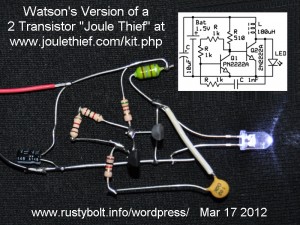
I saw this schematic for a kit that was sold at one time.  It uses 2 transistors, and the author claimed that it was 70 percent efficient.  I wanted to build one to see what my results would be.  Technically it’s not a true Joule thief, which uses only one transistor and has a two winding coil.  The LED is so-so bright, my guess being a current of less than 10 mA.

I made a few changes to the original schematic.  I changed Q1’s collector resistor from 1k to 510 ohms.  The voltage across this resistor when Q1 is off is only 0.9 volts, and the current to the base of Q2 is only 0.9 milliamps.  The Q2 collector current has to be as much as 200 milliamps, so Q2 must use all of its current gain, and Q2 may not turn fully on, its collector voltage may not drop to a small fraction of a volt like it should.  By reducing the resistor to 510 ohms, it doubles the current to Q2’s base, and makes it turn fully on, like a switch.

I used a 180 microhenry choke for the coil, mainly because I have dozens in my junkbox (LOL), but also because the small chokes have very fine wire, and their DC resistance can be too high.  The 180 μH choke has 1 ohm resistance, which is less than the 470 μH called for, but 1 ohm is still higher than it should be.  To keep losses low, the DC resistance should be less than 1/4 ohm.  That’s easy to do if a reasonably high permeability toroid is used.  But hey, when you have a bunch of lemons you make lemonade, so I used one of those dozens of 180 μH chokes.

I changed the two 1k resistors between Q1 base and collector to a 10k trimpot.  When I adjusted the trimpot to more than 3.3k, the supply current went up and the LED got slightly dimmer.  The on/off time of Q2 was changing so that Q2 was turning on longer than it was off, which was wasting power heating just the transistor and choke instead of going to the LED.  My guesstimate is the range of values for this resistor should be in the 3.3k or less, down to 2.0k, but it depends on how much current gain Q1 has.

With the two 1k resistors, the supply current was about 70 milliamps, and I measured the frequency at 85kHz.

I’m working on getting the circuit optimized, and I’ll get to the measurements as soon as I get a better feel for how this circuit performs.  Update 6 mos later – I conclude that since my Supercharged JT is simpler and more efficient, there is no justificaton for trying to obtain better performance from this circuit.

default

2012-02-12 Hybrid 600 Ohm 1:1 Transformer

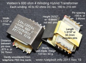
I blogged this a long time ago, but my old blog is gone, so here it is again.  I unsoldered a large number of these 600 ohm hybrid transformers from PBX boards.  Each transformer has four 600 ohm windings, and is used to interface to the PSTN (telephone central office).  Notice that there is a metal shield around the laminations to reduce the interference from stray magnetic fields.  They are the same 1:1 ratio as the Radio Shack 273-1374 600 ohm transformer, but instead of two windings, these have four windings.

The technical details are below.  I recently got an L-C meter that does a good job of measuring iron core transformers in the Henry range.  My AADE LC Meter IIB seemed to have some problems when measuring audio transformers so I didn’t trust it.  Notice that the picture says 160 to 210 mH, but I think the LC meter was reading too high, so I think those values should be ignored.

Transformer is labeled: 124-100164-0004 Rev C

DATATRONIC PT7764  8905  [this is the date code – 5th week of 1989]

Dimensions and weight are given in the picture.

Measurements:

DC Resistance is between 40 and 62 ohms depending on the winding.  This is because the inner winding takes a shorter length of wire than the outer winding – their circumference is different.

1 Winding = 0.125 Hy (each winding measured  the same.)

2 Windings in series = 0.55 Hy

3 Windings in series = 1.3 Hy

4 Windings in series = 1.96 Hy

These would make great matching transformers or for an audio filter. The value of the capacitor for making the two into a tuned circuit can be found here.  You enter the value for the transformer and the frequency and select Hz and H, click on calculate and the calculator spits out the needed capacitance.  The boxes where you enter the values are very light and hard to see, but they are right above the selectors.  If it complains, delete the value from one of the boxes.  I got 0.55 H (two windings in series) and 0.03 uF for the frequency of 1.3 kHz.

When the transformer windings are connected in series, the impedance goes up as the square of the turns.  So if two windings are connected in series, the impedance will be 4 times 600 or 2400 ohms.   If three windings are connected in series, the impedance will be 9 times 600 or 5400 ohms.  When all four windings are connected in series, the impedance will be 16 times 600 or 9600 ohms.  If the transformer is used three windings to 1, that would be 5400 to 600 ohms.  If the transformer is used as an autotransformer and the windings are all four connected in series, then the ends of the windings would be 9600 ohms, and a tap from bottom end to the other end of the first winding would be 600 ohms.  This could be used to match a low impedance earphone (100 ohms to 1k) to a higher impedance transistor, for example.  All that is needed is a DC blocking capacitor between the transistor and the transformer.

Fixed a Problem – I had problems with grounding and hum between my laptop PC and my desktop.  I solved this by connecting the earphone output of the laptop to one transformer winding, and the other winding to the line input of the desktop.  Of course I had to use two transformers, one for each of the left and right channels.  No more hum and noise, and it sounds very good.  Now I can use Audacity (free open source software) on my desktop to make recordings from my laptop.

I also made a Joule Thief out of one of these.  I connected 3 windings in parallel, but the 3 windings in parallel still have a DC resistance of about 16 ohms, which severely limits the maximum current of a 1.5V battery.  The LED lights up, though.

Update Aug 2012 – I’ve built another JT with this transformer.  More info here.

Update Nov 10, 2012 – I used one of these to connect a microphone preamplifier to a 50 foot twisted pair of telephone wire, which has a 120 ohm earphone (from a telephone handset) connected to the other end.  I had this connected directly to the amplifier but I was getting noise and a local radio station in the background.  I soldered a wire from the transformer’s metal shield to the ground side of the microphone connector, so that the transformer core was grounded.  This helped reduce the interference.  The twisted pair was connected to a single 600 ohm winding, and the microphone jack was connected to the remaining three windings in series.  This helped increase the input voltage to the preamp by about three times.

Contact me at my Yahoo.com email address acmefixer (rearranged to avoid spammers) if you’re interested in some.

Here’s another circuit, a 1 kHz audio oscillator, that uses this transformer.

Back to experimenting…


default

2012-02-11 LED Has An Air Bubble

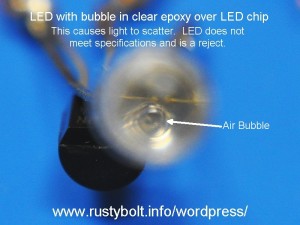
I bought some cheap LEDs from a vendor on eBay, and found that most of them had air bubbles inside of the clear epoxy that makes the lens.  This causes the light to scatter, and the LED will not meet the specifications that are given for the light beam output.  They still put out bright light, but if the LED is used in a flashlight for example, the beam will not be narrow as it was intended to be, and the light will not be as bright within the light beam.

I complained to the vendor, and sent a picture of the air bubbles.  The vendor replaced the defective LEDs, but I got to keep the defective ones, so this must be one of those.  Some vendors are unscrupulous, and will not acknowledge that the LED is defective, since it puts out light.  I had one eBay vendor tell me that if I filed a dispute she would make sure to tell other vendors and that no other vendor would then deal with me (nasty witch!).  I had to go through the resolution process and send the LEDs back and pay for shipping, and I finally got my money back.

This LED happens to be a blue LED.  It seems that the blue LEDs are somewhat more expensive than other colors, and so the vendors are more prone to buy the cheaper rejects, and try to get them to slip through, hoping the buyer doesn’t notice the flaws.  But all one has to do is look into the front of the lens to see the air bubble.

Back to experimenting…

default

2012-02-10 High Voltage Flyback Information

I ran this website in Portuguese through Google translate.  It looks like good info on Flybacks.  I haven’t checked it out enough to say whether or not the site’s information is reliable.

I saw one schematic where the turns ratio between the collector winding and the base winding is 2 to 1.  The supply voltage was shown as 6 to 24 VDC.   I would never run this at more than 12VDC, because the voltage on the base could exceed the 5 or 6 volts maximum.  If it has to be a voltage higher than 12V, then the ratio of the windings should be greater, 3 to 1 or 4 to 1.

© RustyBolt.Info/wordpress
CyberChimps