


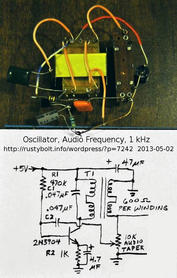
 I was wandering around the pages of the Modern Electronic Circuits Reference Manual, a 1200 page tome by Markus, when I happened to see this odd circuit for a signal generator (see the schematic). My curiosity got the best of me, and I knew I had to build one, since I have a whole lotta these transformers waiting to be used for something.
The circuit is simple. The collector load is two of the transformer’s windings connected in series, giving an impedance of about 2400 ohms. 5VDC is supplied to the collector through these windings. The 0.047 uF capacitor (the dark green one at the far left) is across them, forming a resonant tank circuit. The two other windings are connected in series as the secondary winding. One end is grounded, and the other is connected to a 10k pot (the narrow rectangle at the right). the wiper of this is connected to a 0.047 uF DC blocking capacitor, then to the base of the transistor. As the pot is increased, the feedback gets to the point where it’s enough to maintain oscillation. The frequency is controlled by the inductance of the primary winding and the 0.047 uF capacitor across the winding.
The circuit I built was almost the same as the schematic, except for the 470k resistor, which I changed to 560k. But this value would need to be adjusted to accommodate different transistors with different current gains – just about any transistor should work in this circuit. With the 560k, the 1k emitter resistor had 0.9V across it, indicating that there was about 0.9 mA of emitter current.
The first time I powered it up and turned up the feedback pot, nothing happened. I knew that I had the feedback winding connected backwards, so it was negative, not positive. I unsoldered it and soldered it the other way around, and powered it up. When I advanced the feedback pot, I got a sine wave on the o’scope. But it was slightly distorted (more on this below). The frequency was about 1200 Hz when the pot was adjusted for minimal distortion. But it was touchy, a slight change and the sine wave would drop to zero. When it was turned up slightly, the sine wave was a full 5V peak to peak, with some distortion at the bottom. The frequency also dropped, to about 1050 Hz, but that varied depending on the pot setting.
If the circuit is used like this, it would require the feedback pot to be a user settable knob on the front panel, because the amount of feedback would need to be frequently adjusted when the temperature or supply voltage changed or the load was changed. To prevent this, the circuit should have an AGC (automatic gain control) circuit added to it to maintain the gain at just the right point with no need for manual adjustment.
The feedback pot could be adjusted so there was no distortion, but it was near the very end of its low end. I measured the resistance with the DMM and it was only 150 ohms. So the ratio was 150 ohms to 10 k, or a dividing ratio of about 67. The pot would not have been settable if it had been a linear pot. This should be changed to a 10k resistor in series with a 500 ohm pot to give a finer adjustment.
Other modifications
This circuit is just one of many configurations for an oscillator. The feedback winding could be changed to one of the two windings, and the remaining winding could be used for the output. As I said, the frequency will change with different loads. To prevent this, an attenuator should be used between the transformer and the output, with enough attenuation to make the frequency change minimal. Or another transistor could be used as a buffer stage, to isolate the output load from the transformer.
To get the circuit to put out 1000 Hz, it would need to have a larger capacitance across the primary winding. The 0.047 uF cap could be changed or additional capacitance added to it. It should probably be something close to 0.068 uF total.
In an audio oscillator, one disadvantage of using a transformer for the frequency determining element is that it is subject to electromagnetic interference, and is expensive and bulky. If you get this near a power transformer it might pick up some hum, but the core has a metal shield around it on three sides to minimize this problem.
One advantage of the transformer is that if this circuit is going to be used for the modulation of a transmitter, the DC for the transmitter can be passed through the windings with very little power loss. That is why the AM transmitters used a transformer to amplitude modulate the final RF output stage.


Thank you for the circuit. Can you please enlarge the image so that it is clearly visible.
Thank you.
You have to click on it more than once to enlarge it.