This Overunity Research forum thread seems to be headed in the direction of Steve Jones’ COP greater than unity assertion.
http://www.overunityresearch.com/index.php?topic=1171.msg21438;topicseen

This Overunity Research forum thread seems to be headed in the direction of Steve Jones’ COP greater than unity assertion.
http://www.overunityresearch.com/index.php?topic=1171.msg21438;topicseen


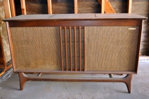
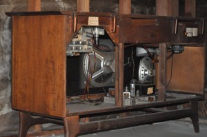
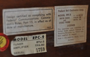
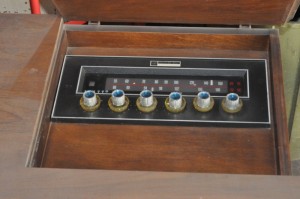
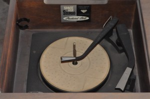 FOR SALE – The Stereo applies only to the record player. It’s a little dusty. Well, maybe more than a little, it’s been sitting there for decades. You have to click on the picture more than once to get it to enlarge.
Update Mar 4 – I sold it to a guy who said he was going to fix it up. I got an extra $20 for delivering it.
Feb 29, Leap Day. They say that St. Patrick gave the women permission to ask a man to marry on the 29th day of February. The following is a watsonseblog from Jun 13, 2011.
For those who are new to Joule Thiefs, here is a 9 minute video that shows what it takes and how to make a Joule Thief. The guy is bringing low technology to the poor people of countries such as Egypt and Nepal. Another webpage of his accomplishments can be read here.
Here in Southern California, there is no need for a fireplace, but many houses have them. The residents that have them probably don’t use their fireplace much, since they are very inefficient, and if they burn wood or logs, it can cost quite a bit. Not to mention they would be a big contributor to air pollution. That’s probably the reason why many fireplaces have a “log” with a natural gas burner inside.
I remember many years ago when the TV stations broadcast during Xmas Eve, they showed a picture of a fire in a fireplace. They didn’t have automatic programmed digital playback equipment then, and their tape players would have required one of the staff to miss his vacation to be at the studios to man the equipment. So they just let everyone go home for vacation and pointed a camera at the fireplace picture, probably a Xmas greeting card. You could turn your TV on and the set would be your fireplace for Xmas eve. This makes me wonder if it might be easier to just record a ten minute video of a real fireplace, and put it on Youtube for everyone to enjoy. Just let it loop and playback over and over again.
I’ve been thinking of how to scale up Quantsuff’s Electronic Fireplace to the size of a small fire in a fireplace. The light output is going to have to be more powerful, maybe a few watts of LED light. I was thinking about using a combination of yellow, amber and orange LEDs to get some color that’s similar to a fire. If the different color LEDs are connected independently to the randomized outputs of the drivers, then some variation in the color temperature of the light will be seen.
But it will cost a fair amount to get some amber LEDs that put out high power. I thought that using old technology might be cheaper and just as good visually. If an incandescent light is run at much lower voltage than it rated voltage, its lifetime can be hundreds of thousands of hours, and its color temperature might be the same as the light from a fireplace. The bulbs would never have to be replaced. I have a whole box of 1152 12V, 21CP auto tail light lamps (CP = candlepower). I’ll have to try one on a lower voltage supply and see how it looks.
I put one of the 1152 lamps on a power supply. At 3 to 4V and about 3/4 amp, the light put out a nice orangish amber glow. But it got quite warm, so it will have to be mounted in something that won’t melt. The filament has a slow response, much like the light from a fireplace. I don’t need to slow the turnon and turnoff so a square wave would work. More to follow.
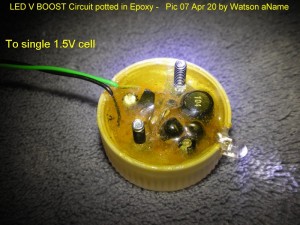 I took this pic on Apr 20, 2007, about 5 years ago. I potted the two screws so I could bolt it down to a flat surface with two nuts. Burt, our late computer operator, used to tell me when I was searching for a screw and nut, “There’s no shortage of nuts around here.”
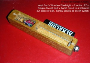 Here’s a two LED joule Thief project that I did about a decade ago. I took the first picture in Feb 2007, more than 5 years ago, and wrote a watsonseblog about it. The second pic was taken even earlier. It works pretty good. The oak case is definitely unique. Later I used a thin piece of oak veneer as the cover.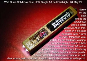
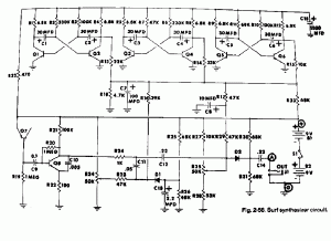 A long time ago I came across this schematic of a Surf Synthresizer circuit. I remember reading something about this earlier, and I wanted to build one just to see if it actually worked. It’s a set of three astable multivibrators with their output voltages summed and low pass filtered, and the result is used to modulate the amplitude of a zener noise generator (actually it’s Q7, a transistor, with the emitter to base junction used as a zener). The bias on the diodes are used to modulate the amplitude. The astable MVBs run at less than 1 Hz, so their sum is a slowly varying voltage, similar to the patterns on the waves as they hit the shore.
Today, I think it would be much easier to simulate this circuit with a PIC or whatever microcontroller. The circuits could be easily simulated in software. I’m an analog type of person, so I tend to do things the hard way, and I would use solder as my programming language and build the circuit as shown in the not-so-clear schematic. The output is line level, for driving an amplifier and speaker. Thus in addition to this synth, I would have to build an amplifier, which sounds like fun. Or maybe I should just feed it into a mixer so it comes out of the speakers I use on my PC. Or maybe I should go out in the garage and dig out a pair of old speakers that I had long ago on an older PC. Probably the best idea, huh.
The junction of Q7 breaks down at somewhere between 6 and 10V, so a single 9V battery won’t be enough to power this circuit. They used two 9V batteries in series, but this thing is probably going to be used as a sleep aid, and batteries will quickly be depleted after a few nights. So one thing that is needed is a wall wart adapter that can put out somewhere around 15 to 18 volts. and it will have to be well filtered to prevent the AC hum from getting into the amp, however the current demand is very low, probably only a few milliamps.
The rest of the circuit might work okay on a lower voltage, maybe 9V. It might be a good idea to add a buffer stage to the output: a transistor connected as an emitter follower so that the output doesn’t load down the circuit. A transistor and 4.7k resistor should be all that’s needed.
Back to experimenting…
 I built this circuit long ago and I can’t remember what I intended it to be used for. It’s kind of different. The CdS photocell is glued into the end of a 3/8 inch O.D. by 1 inch long piece of black plastic, probably cut from the body of a cheap ball point pen. This makes the photocell directionally sensitive.
CdS photocells are slow to begin with. Also, the 56k R1 is a high resistance so the light level must be relatively low. The CdS photocell is AC coupled to the rest of the circuit so the circuit was meant to respond to changes in light level. The circuit uses four transistors which means it has a very high gain and hence high sensitivity (more about this below). The R4 and C1 bypass the power supply to ground or common. The coupling capacitor C2 is large for good low frequency response and the low pass capacitors C3 and C4 limit the bandwidth to very low frequencies, so I believe that it was not for a remote, but for some form of motion sensing. As I block and unblock the light on the photocell, I can tell from the LED’s slowness that the circuit performs only for slow changes in light.
The Q1 and Q2 transistors are very high current gain, more than 500. I got them from some surplus place and they are numbered 7225, an odd number, probably a part number for some company’s inventory. They are in the TO-106 package, which is no longer being made. Both the TO-105 and the larger TO-106 packages were very popular. It’s a drop of black epoxy on top of a ceramic cup. I remember reading someone’s recollections about this at one time popular transistor package. The company (Fairchild or National?) received an order for thousands of the transistors. They asked the customer what kind of transistor they would like. The customer replied that they didn’t care; they were going to use them for the eyes on their teddy bears. (!)
I’ll have more to say when I do some more experimenting with it.
I thought that it would be much more appropriate if the current limiting circuit was made to be polarity independent, so it would work with AC as well as DC of unknown polarity. I took the easy route: I connected the current limiting circuit up to the + and – leads of a bridge rectifier. I realized that it would add a volt and a half or so to the minimum supply voltage.
The limiting circuit (Fig.1 here) was the classic one: a transistor for passing the current, with a low value resistor in series with the emitter, to ground. The voltage across this resistor is used to turn on another transistor, which then shunted away the base bias current of the pass transistor. This bias current was from a 22k resistor to the collector of the pass transistor. The only difference between my circuit and the one in Fig.1 is that mine has a 470 ohm resistor in series with the base of Q2. The whole thing fit on a small circuit board, with two white wires since the polarity was not important.
Back to experimenting…