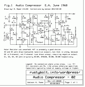
 See my General note at the bottom for some info on audio compressors in general. I had this hand drawn schematic in my SCH files folder, dated from 8 years ago. The actual schematic was from “E.A.” dated 1968. I can’t figure out what E.A. is. I would imagine that the E stands for electronics, but I don’t know about the A. I found a few mistakes and omissions, so I updated the hand drawn schematic. Then I decided that the schematic would look much better if it were drawn in ExpressSCH, so I did that. Took me quite a few TV commercial breaks to get through it all.
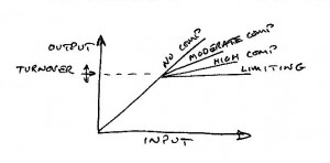
Basically it’s an audio amplifier with a variable resistance FET in series with the emitter bypass capacitor. This reduces the gain when the FET is biased with a reverse voltage. There are adjustment pots for the amount of compression and for the turnover point where compression starts to take effect. For more, check out the schematic and graph photo.
Update May 19 So far, I’ve had two comments from others on it (click on the pic 2 or 3 times to see comments). One comment mentioned that this circuit originally used germanium transistors, which makes sense since it is dated 1968. The others and I have redrawn it with silicon transistors, but I have not checked to see if the resistors have been changed to what they should be for silicon. It may be that if it’s built as shown, the values may be off enough to cause problems.
The two transistor microphone amplifier stage has a gain that depends on the ratio of the 56k resistor and the internal resistance of the MPF102 JFET. One bad thing about JFETs and especially the MPF102 is they have a wide variation in the internal resistance; in the case of the MPF102, it’s ten to one. So if you just put any MPF102 into the circuit, you may get a wide variation in performance. The way to avoid this is to select a MPF102 with a higher IDSS. A higher current means lower internal resistance. The amplifier will then have a greater range between the maximum and minimum gains.
Another way is to put more than one JFET in parallel. In this circuit you can put 2, 4 or more JFETs in parallel to decrease the total internal resistance. With more than 1 FET, I would change the 1 Meg compression adjustment pot to a lower value, such as 500k or maybe less.
Another way is to use a JFET that has much lower internal resistance. I think the J105 may be used for this purpose. Instead of using a JFET, it’s possible to use a MOSFET such as the 2N7000, which has an internal resistance of 5 ohms. But since it is an enhancement mode FET, it must be biased to be turned on by a resistor or two. The required voltage is between 0.8 and 2.4 volts.
The 56k resistor may also be modified to get better compression or range.
Update May 20 – I’d like to thank Darren for sending me the original schematic. As he said, it used a 2N4360 P-channel JFET, which is the opposite polarity compared to the MPF102. The output of the rectifiers and filter cap is positive, which then goes through the 1 meg pot and then to the gate of the JFET.
Update May 24 Further information about other compressors – I had a schematic of a battery operated cassette recorder. The way the microphone signal was compressed was with a regular transistor, not a FET (I’ll call it the BJT). The emitter of the BJT was connected to ground. The base was connected to the rectified and filtered DC from the output of the preamplifier. The higher the microphone level, the more current was sent into the BJT’s base. Then I was puzzled as to why the BJT’s collector was connected directly to the microphone. But that’s how it worked. The more current that went into the base caused the BJT to have lower resistance between the collector and emitter. The BJT was being used for a variable resistor to shunt more of the microphone’s signal to ground as it increased. It worked fairly well; the microphone signal was compressed to prevent overloading the microphone preamp.
This same technique can be applied with a JFET or MOSFET. The drain and source of the FET are connected across the microphone. A loud microphone signal causes the greater voltage at the gate to turn on the FET and shunt the microphone signal. The FET can have a very wide range of resistance, from millions of ohms to less than 5 ohms.
Another schematic of an audio compressor that uses an opamp. Some of the output of the opamp is fed back to a red LED. The light from the LED shines on a CdS photocell which is connected from the output to the inverting input, The more light, the lower the CdS resistance, and the more negative feedback to the opamp, which reduces its gain. The disadvantage of this is that the CdS photocell is slow to change its resistance, so the fast, loud signal may not be compressed quickly enough during the first fraction of a second. That excessively loud signal may overload the opamp.
General – The compressors used in radio and television broadcasting are very expensive and are sophisticated, with bandpass filters that allow compression of a band of frequencies. It would imply that a simpler compressor covering the whole audio band would therefore not do as good a job as these more expensive ones. But with audio that varies greatly in loudness, something is needed to prevent overload of the amplifiers and audio equipment. A simpler wide band compressor will achieve this and help prevent overload.