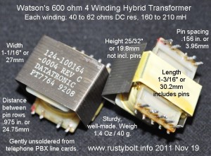
 I blogged this a long time ago, but my old blog is gone, so here it is again. I unsoldered a large number of these 600 ohm hybrid transformers from PBX boards. Each transformer has four 600 ohm windings, and is used to interface to the PSTN (telephone central office). Notice that there is a metal shield around the laminations to reduce the interference from stray magnetic fields. They are the same 1:1 ratio as the Radio Shack 273-1374 600 ohm transformer, but instead of two windings, these have four windings.
The technical details are below. I recently got an L-C meter that does a good job of measuring iron core transformers in the Henry range. My AADE LC Meter IIB seemed to have some problems when measuring audio transformers so I didn’t trust it. Notice that the picture says 160 to 210 mH, but I think the LC meter was reading too high, so I think those values should be ignored.
Transformer is labeled: 124-100164-0004 Rev C
DATATRONIC PT7764 8905 [this is the date code – 5th week of 1989]
Dimensions and weight are given in the picture.
Measurements:
DC Resistance is between 40 and 62 ohms depending on the winding. This is because the inner winding takes a shorter length of wire than the outer winding – their circumference is different.
1 Winding = 0.125 Hy (each winding measured the same.)
2 Windings in series = 0.55 Hy
3 Windings in series = 1.3 Hy
4 Windings in series = 1.96 Hy
These would make great matching transformers or for an audio filter. The value of the capacitor for making the two into a tuned circuit can be found here. You enter the value for the transformer and the frequency and select Hz and H, click on calculate and the calculator spits out the needed capacitance. The boxes where you enter the values are very light and hard to see, but they are right above the selectors. If it complains, delete the value from one of the boxes. I got 0.55 H (two windings in series) and 0.03 uF for the frequency of 1.3 kHz.
When the transformer windings are connected in series, the impedance goes up as the square of the turns. So if two windings are connected in series, the impedance will be 4 times 600 or 2400 ohms. If three windings are connected in series, the impedance will be 9 times 600 or 5400 ohms. When all four windings are connected in series, the impedance will be 16 times 600 or 9600 ohms. If the transformer is used three windings to 1, that would be 5400 to 600 ohms. If the transformer is used as an autotransformer and the windings are all four connected in series, then the ends of the windings would be 9600 ohms, and a tap from bottom end to the other end of the first winding would be 600 ohms. This could be used to match a low impedance earphone (100 ohms to 1k) to a higher impedance transistor, for example. All that is needed is a DC blocking capacitor between the transistor and the transformer.
Fixed a Problem – I had problems with grounding and hum between my laptop PC and my desktop. I solved this by connecting the earphone output of the laptop to one transformer winding, and the other winding to the line input of the desktop. Of course I had to use two transformers, one for each of the left and right channels. No more hum and noise, and it sounds very good. Now I can use Audacity (free open source software) on my desktop to make recordings from my laptop.
I also made a Joule Thief out of one of these. I connected 3 windings in parallel, but the 3 windings in parallel still have a DC resistance of about 16 ohms, which severely limits the maximum current of a 1.5V battery. The LED lights up, though.
Update Aug 2012 – I’ve built another JT with this transformer. More info here.
Update Nov 10, 2012 – I used one of these to connect a microphone preamplifier to a 50 foot twisted pair of telephone wire, which has a 120 ohm earphone (from a telephone handset) connected to the other end. I had this connected directly to the amplifier but I was getting noise and a local radio station in the background. I soldered a wire from the transformer’s metal shield to the ground side of the microphone connector, so that the transformer core was grounded. This helped reduce the interference. The twisted pair was connected to a single 600 ohm winding, and the microphone jack was connected to the remaining three windings in series. This helped increase the input voltage to the preamp by about three times.
Contact me at my Yahoo.com email address acmefixer (rearranged to avoid spammers) if you’re interested in some.
Here’s another circuit, a 1 kHz audio oscillator, that uses this transformer.
Back to experimenting…


