default

2012-02-09 1/4 Volt Joule Thief

I found something that drew my attention, a Joule Thief that operates on less than a half volt and uses a silicon transistor.  Here is a short Youtube video of a circuit operating at less than 1/4 volt, and it says it is using a BC107, which is silicon.   I said to myself at first that’s not possible, but then I stopped the video and checked things out closer.  First off, I haven’t tried it yet, I need to wind a coil and try it (I have now, see update below).  What I saw was the LED lit, dimly, and the cell voltage at 0.136 volts.  The transistor looked like a BC107 which is in a metal package.  I saw the schematic of the circuit but he left the LED out of the schematic.  Also it did not use a resistor, so the cell or power supply must stay well below a half volt; if it goes above a half volt, the current would become excessive.

Then I saw the wiring, I saw that the LED was connected between the collector and base.  But I couldn’t tell the polarity of the LED.  My guess is the LED is connected with the cathode to the base, so that negative pulses on the base cause the LED to light when they reach negative 3 volts.  But if I do make the circuit, I will just connect two LEDs in parallel with the cathode of one connected to the anode of the other.  If one LED lights and the other is not lit, then I will know which direction the LED should be connected.

When I thought about it, the high 10 to 100 ratio of the collector and base windings could cause the 1/4 volt change on the collector to be 2.5 volts change on the base, enough to light the LED and turn on the base of the transistor.

I did a similar experiment, and I think I blogged it in my old blog.  I took a conventional JT and removed the LED from across the emitter to collector.  I connected the LED cathode to the base, and the anode to the negative.   Leaving the collector unloaded (connected only to the primary winding) allowed the modified JT to start at 0.45V, and I think I was using a BC550C, which is a low noise, high gain version of the BC547.

But the coil I was using was 1:1, so there was no V increase from collector to base.  By putting 10 times as many turns on the feedback winding, the author may have been able to get it to start at a much lower voltage.

I’ve read that if you plot the V-I curve for a silicon junction below 0.6V on a log graph, it is close to a straight line.  In other words, below 0.6V, the current doesn’t drop rapidly to zero, it behaves square law, or inverse square law, I forget  which.  Anyway, there could be a few microamps at a few tenths of a volt, and with enough turns on the core the base drive voltage may be enough to get it started.

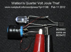
Update Feb 12  I built the circuit, but I cheated.  I didn’t want to wind a hundred turns on to a toroid, so I picked a 420 microhenry choke, and wound 20 turns of 30 AWG on the outside and taped it in place with black electrical tape.  I don’t know what the actual turns ratio is, but I would guesstimate it’s more than 5 to 1. The added winding is the primary, and the choke’s winding is the feedback winding.  I didn’t know what the winding polarities were when I first hooked them up.  I had to reverse one winding to get it to work.  I used no resistor, as he did not use one in the video.

The JT starts up at 0.4V, but it draws excessive current; I had to set the power supply’s current limit at 200 mA.  Once I got it started, I turned down the voltage until it was running at 240 millivolts, which is slightly less than 1/4 volt. The supply current dropped down to about 60 mA, and the LED still stayed lit.

A clarification of the LED connection polarity: it is connected with the cathode (flat spot) to the base, and the anode to the collector.  In the picture the LED is lit up, but the flash overwhelms it so it doesn’t look very bright.  The frequency is about 70kHz.

In conclusion, the circuit is a conventional Joule Thief with three changes: The coil has many more turns on the feedback winding, the resistor is zero ohms, and the LED is connected between base and collector (see above paragraph).   A germanium transistor* will easily work at these low voltages, so  it’s not something to write home about.  But it is interesting to squeeze those last few tenths of a volt out of a dead cell with this circuit.

I am also going to have to make a  simple power supply that will supply less than 1/2 volt at a few hundred milliamps current limited.  BTW, this circuit would be a very good match for converting  the half volt output of a solar photovoltaic cell into a higher voltage.  The single solar cell has the inherent current limiting so that when this circuit takes off, the cell’s voltage will drop, limiting the current to a safe value, as long as the solar cell supplies the correct maximum current – it´s not too big for the circuit.  And that size should be determined in bright sunlight, because there is no resistor in the circuit and it will destroy itself if the cell voltage becomes as high as the base to emitter voltage.  But a solar cell is silicon and cannot put out more than 0.55 volts, which limits the voltage, so the main concern is the circuit´s power handling capability.

* Germanium transistors are no longer made in mass production quantities.  The prices for germaniums that were once very common are now very high – several dollars apiece.  Germaniums cannot be purchased at the local electronics store. so they are not really useful  for any circuit that might be built nowadays.  Also, very low voltage Joule Thiefs can be built using the MOSFETs and JFETs.  See my blogs here and here for more on this.

Back to experimenting…

default

2012-02-08 Useless Wire Stripping Tool

This combination wire stripper and cutter is the worst tool I’ve ever purchased.  I purchased it at the local hardware store (they’re now out of business) and didn’t notice the sign on the cabinet.  I got home and tried the wire stripper out on a piece of 24 AWG stranded wire.

When I put the wire between the jaws at the right end )(top picture) and squeezed the handles, the outer jaws grasped the wire and the inner jaws cut the insulation and pulled it off. All was fine and dandy.  When I let go of the handles, the two jaws went back together as expected, and the now stripped strands were crushed and crumpled by the jaws as they went back together.  The wires were now a very fine tangled mess!

I went back to the hardware store and asked for a refund.  The boss told me no, and to read the sign on the cabinet.  The sign said NO REFUNDS ON TOOLS.  He said to contact the manufacturer.

I sent a complaint letter to the manufacturer, some company in Hawaii, and asked for a refund and RMA number (return materials authorization).  I received back a package with a letter apologizing and it included two more of the same tools!!!  Like, do I need two more useless tools?  NO!

BUYER BEWARE!!

default

2012-02-05 Joule Thief Voltage Protection

I’ve talked about this before: the Joule Thief has certain vulnerabilities that need to be considered when making a new design.  Suppose we build a simple conventional JT, with a single LED and a 1.5V battery.  The coil has two windings, each the same number of turns, probably wound bifilar – the windings are wound at the same time and have the same number of turns.  This means that the windings have a 1 to 1 ratio, which means the voltages are the same on each winding.

When the output of the JT goes to a single LED, the voltage across the LED will not be more than 3 to 4 volts.  The coil reflects this voltage back to the feedback winding, which means the negative voltage on the base will not be more than the LED voltage (actually less).  This 3 to 4 volts negative will not exceed the maximum for most transistors, which is typically 5 volts.

This simple JT design is operating properly, within its limits.  There are several limits, one of which is the maximum voltage across the transistor.  During its operation, the LED forward voltage drop of 2V for red or 3.2V for blue or white means that as long it is in the circuit, the LED will limit the maximum voltage to 3.3 volts.

But some experimenters disconnect the LED and expect the voltage to rise, and it will rise (see note).  They believe that the transistor’s maximum collector breakdown voltage will limit the voltage.  This voltage is generated by the collapsing magnetic field within the coil.  The collapsing magnetic field is also inducing a voltage in the feedback winding, of the opposite polarity.  The negative voltage is on the base, so when this voltage rises, it will reach the maximum emitter to base voltage, which is much lower than the maximum collector voltage.  The emitter to base junction will break down, and current will flow and limit the maximum voltage before the maximum collector voltage is reached.

The problem is that when the emitter to base junction breaks down and a small current flows, it causes the current gain to deteriorate, so after a short while, maybe tens of seconds or a few minutes, the transistor’s current gain can be measured and it will be much less than the current gain before the breakdown.  And this damage is permanent; the transistor will never recover its original current gain.  Some circuits tolerate this loss without losing their usefulness.  The Joule Thief seems to keep running without stopping.  But the transistor’s performance suffers, so it must affect the Joule Thief’s performance somewhat, even though the JT continues to operate.  If this abuse continues, my guess is that the performance will continue to deteriorate, but when it will no longer operate is anyone’s guess.

My opinion is that this abuse should not be allowed to occur.  As long as the LED is here as a load, the abuse will not occur.  But some experimenters want to operate this simple Joule Thief with more than one LED.  They attempt to operate it with two or more LEDs in series, so the voltage across the LEDs might be 6.6, 9,9 or more volts.  The same voltage, but negative is on the base, and that exceeds the 5V maximum.  Those experimenters all fail to take precautions to protect the base from this negative voltage.  The protection is easy to do.  All that is needed is a diode (1N4148) with its cathode or banded end connected to the base, and the other lead connected to the emitter.  When the winding applies a negative voltage, the base goes negative to 0.6V, the diode conducts and the negative voltage cannot go any more negative.  The excess energy is dissipated in the 1000 ohm resistor.  Instead of a diode, a LED can be used.  When the negative voltage gets to 3.3V, the LED conducts and the same thing happens, but it will light and show the experimenter that it is doing its job.  The negative 3.3V is well within the 5V maximum so the base is protected.

This form of protection should be used on all Joule Thiefs that the experimenter might abuse.

Note: When the current through the coil is shut off, the collapsing magnetic field will produce a high voltage.  If the circuit is changed to the similar two transistor voltage boost circuit with a single winding on the coil, the voltage could rise to as high as the collector breakdown voltage for the transistor.  This could be a hundred volts or more for a high voltage transistor. But when the second feedback winding is added, the voltage across it gives the coil a “sneak path” for high voltage to go when the field collapses.  If you are experimenting and do not want this other escape route then you should not use the two winding design.

default

2012-02-04 Joule Thief – Multiple LEDs

Full Brightness Myth – The typical  JT (Joule Thief) uses a single transistor, draws 80 milliamps from the 1.5V battery, and puts out up to 20 milliamps to the 5mm white or blue LED. Let us consider this 20 milliamps “full brightness” or “full brilliance”, which is a term often used but has no quantitative meaning because it uses no unit of light measurement.  I see this term used by a JT builder who connects 12 LEDs in parallel to a JT that uses a single pipsqueak 2N3904, and claim the LEDs light to “full brightness”, a totally unsubstantiated claim.  A typical JT using a 2N3904 puts out 8 or 9 milliamps to a single LED, and when 12 are connected in parallel, each LED will then get about 3/4 of a milliamp, which, in fact, is less than 4 percent of the current needed for “full brightness”.  Such a myth!

You can’t get something for nothing.  You will be spending 12 times as much for the LEDs and get the same amount of light from 1 or all 12.  “There ain’t no such thing as a free lunch”, you know.  Putting bigger tires on a race car won’t make it go faster if you’re using the same underpowered engine (2N3904).

What should we do?  First off, get rid of the 2N3904 and replace it with a 2N4401, PN2222A or best, a BC337-25.  This will bring the total LED current up to about 15 to 20 mA.  Divided 12 ways, that’s still only about 1.5 mA per LED, still way too low.

Let’s Get Serious  We need a dozen times more current to each LED.  The quickest way, design-wise, is to give each LED its own JT circuit.  Just use 12 coils, 12 transistors, and 12 1000 ohm resistors, and duplicate 12 JTs.  Each JT will put out roughly 17 mA to its own LED, but at 83 mA battery current per JT, that is a total of 1 AMP battery drain.  The poor AA cell’s voltage will drop down to 1.3 volts or even less, and that will reduce the output of each JT circuit.

To help with this problem, I would put only 6 LEDs per battery.  A half amp is still a lot for a single AA cell, but the voltage won’t drop so much.  Then the next thing is to use a transistor that can handle 6 times as much current as a BC337.  The 2SD965 is capable of 5 amps, but it’s hard to find.  The Fairchild Semi KSD5041 is the same and is available from Mouser for a reasonable price.  Attention!  The KSD5041 is a Japanese transistor and has a pinout of E C B.

The resistor will have to be lower, I would guess that a starting point would be 330 ohms.  With this much current, a 100 uF capacitor across the battery is a must have.  The core for this JT should be heavier, I would use a FT87-75 available from surplussales.com.  I would use four windings wound quadrifilar, of 24 AWG solid insulated wire, with 3 of the windings connected together in parallel for the primary winding.  A short piece of cat 5 cable should work, long enough for ten turns.

Will this put out enough current for 6 LEDs?  I haven’t tried it yet, so I don’t know for sure.

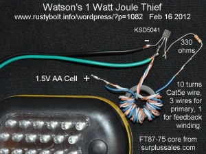
Update Feb 16   I put one together (see picture) using a 27 LED light that I got from OSH for 6 bucks.  This yellow and black light has 24 LEDs on top and 3 on the end.  It has a 3 AAA cell holder, and draws so much current that the batteries quickly go dead.  So I drilled holes through the case for the two wires and soldered them to the holder contacts.  Note that if you do this, the pushbutton switch allows you to switch from 24 LEDs to 3 LEDs and then off.  You do not, ever, want to disconnect the LEDs from a JT, for the possibility of damaging the transistor.

The coil is wound with 10 turns of Cat5e solid wire, three wires for the primary, and 1 for the feedback winding.  The length of each wire was 14 inches or 0.35 meters.  The core was the FT87-75 from surplussales.com, and each winding of the coil measured 350 microhenrys.  I used a 330 ohm base current limiting resistor for a start.

On a 1.5V power supply it drew 210 milliamps, and the frequency was 8 kHz.  Assuming about 50 percent efficiency, that is about 50 milliamps LED current, more than 3 times better than the typical JT, but still far short of the 120 mA we want for 6 LEDs.  I think removing a few turns from the coil and reducing the resistor would help increase the LED current.

Update Feb 18  I reduced the resistor to 100 ohms, and the supply current went up to 280 milliamps, an improvement.  Then I removed three turns so the primary and feedback windings now have 7 turns.  The supply current went up to 350 milliamps, and the frequency was 12.5 kHz.  Assuming 50% efficiency, that calculates to about 13 milliamps for each of the 6 LEDs.  This is at the low end of what I would expect from a multiple LED JT.  Note: of course this ridiculous 24 LED monster light has four times as many LEDs, so each LED is only getting about 3 milliamps, which isn’t all that bright.  But it’s doing pretty good, all things considered.

Back to experimenting…

default

2012-02-03 Fukushima Daiichi – What Happened

I watched Nuclear Aftershock on PBS Frontline a few weeks ago.  I think everyone should watch this, because nuclear power affects almost everyone of us.

I went on a group tour of SONGS (San Onofre Nuclear Generating Station). The rep gave his spiel and when finished he asked “are there any questions?”   I raised my hand and asked “Where does the nuclear fuel come from and how much does it cost?”.  He quickly dodged my question by giving information unrelated to the question.  I got the feeling that I had asked him to give away some sort of secret.

I´m telling a brief, simplified version of what I have learned, in the hope that the casual reader will learn enough to pursue further information on their own.  A good source on this subject is NHK World nhk.co.jp.  UPDATE: watch “Inside Japan’s Nuclear Meltdown” online at www.pbs.org/frontline

The way it works  When the fuel rods are put into a nuclear reactor core, they are enriched uranium.  The control rods are partially pulled out and the core reaches critical, and begins to produce enormous amounts of heat, which is what is used to make steam to generate the electricity.  The amount of heat is enormous, billions of watts in the space of a house.  The coolant must be kept circulating to prevent the heat from melting the core.

After it has been in operation awhile, the byproducts of fission have accumulated and the fuel rods are no longer just enriched uranium.  These byproducts of fission are unstable and will keep on breaking down, producing more heat.

When a nuclear reactor is shut down, the control rods are inserted into the core and stop the uranium from fissioning.  But even so, the byproducts of fission are still there, breaking down and making decay heat.  The heat is nowhere as much as it was while the reaction was going on, but it is still a huge amount of heat, and can melt the core.  Therefore the reactor must be fed coolant for weeks until the byproducts slow down their breakdown and the core reaches cold shutdown.  If

In order to keep the coolant circulating, the reactor has pumps and power, and backup power and backup generators, and backups to the backups, just to prevent the core from melting after it has been shut down. These must keep the coolant circulating for weeks until the core has cooled down. If this cooling system fails, it is the beginning of a major catastrophe.

What happened  Fukushima Daiichi was built in a location that had been hit by huge tsunamis in the past, one of which was the massive tsunami of 869, a part of Japanese historical records.  Even though it was known that that tsunami had done severe damage, the builders of the plant chose not to build the sea wall around the plant high enough to prevent damage from another tsunami like those of the past.

As a result, when the earthquake came on March 11, 2011, the nuclear reactor plants in Japan, including Fukushima, shut down as they were supposed to.  The following tsunami was so huge that it breached the sea walls of Fukushima Daiichi, flooded the plants and damaged the plants and backup generators, and the coolant could not be kept circulating in the core.  The temperature of the cores rose, finally causing meltdown and explosions that spread radioactive material over an area tens of kilometers downwind.  These areas had to be evacuated and people have not been allowed to go back because of the radiation.  It has been nearly a year since the accident happened.  The evacuated people cannot go back to the contaminated areas, possibly for decades.

The plant had 6 reactors, and some were not running at the time of the disaster. The plant was damaged beyond repair and may take many years to demolish or encapsulate.  It was eventually brought under control, but the cleanup of radioactive material spread over so much area will take massive amounts of money and manpower.  The accident and coverage by newsmedia has given the nuclear power industry a black eye and the public has the perception that nuclear power is unsafe.  This is especially true in Japan, where the atomic bombs were dropped at the end of World War 2.

Update Apr 10 – I ordered Nuclear Aftershocks on DVD, and watched it again.  More tidbits from the program.

“We have not found a pollution free(?) baseload electric power .. other than nuclear power.”

I don’t think this statement is valid.  Geothermal and hydroelectric power are pollution free and can deliver power 24 hours, 7 days a week.  There has also been discussion about storing solar thermal energy in molten salts so that the solar thermal plant can still produce power after sunset and during cloudy days.  I’m not sure if there are any installation utilizing this, though.

He said, “Nuclear power has a great future.  But I’m biased – I’m an engineer.”

The NRC required Ft. Calhoun Nuclear Reactor in Nebraska to install watertight doors.

The  North Anna Nuclear Power plant was just 11 miles from the 5.8 earthquake last year.

“I think we still have some lingering issues that we want to get resolved.”  Jaczo, of NRC on fire hazard issues.

Indian Point NPP is very near the Ramapo fault.

“The U.S.has 104 nuclear reactors, the largest number in the world, but they are all old plants.”

The Fukushima nuclear accident released one tenth of the radioactive materials that were released at Chernobyl.

“It will probably take 25 years to cleanup Fukushima.”

It took (from March) until December to achieve cold shutdown.

My thoughts.  After the Fukushima meltdown, the Japanese and German people say they do not trust nuclear power.  But the nuclear power is not the problem, it is the failure of the people who designed the plants with two problrms.  The first failure was to design a system that has a critical vulnerability.  This is the vulnerability that caused the Fukushima nuclear accident.

The second problem was they understood that the vulnerability had to have safety systems to prevent it from occurring, but they failed to anticipate every possible adverse situation (such as a strong earthquake) that might initiate a series of events that could cause a catastrophic meltdown, as in the case of Fukushima.  And failure of the system to upgrade the deficiencies in a timely manner when they are later discovered, as in Fukushima.

Perhaps this deserves further explanation.  For want of a nail, the kingdom was lost.  Or in other words, the smallest details can make or break a system.  In the program, they discussed how the above nuclear power plants installed, among other things, water tight doors to prevent flooding of the emergency backup power system.  One could also argue that it is not possible to anticipate every adverse situation and therefore nuclear power cannot be inherently safe.


 NHK News   Wikipedia article

Tags:
default

2012-02-02 Disposable Camera Flash

One of the favorite devices of the ¨free energy¨ experimenters is the disposable camera flash.  These circuits can be obtained for free from the local stores that process the disposable camera pictures (I got mine from Rite-Aid).  However if you don´t wan to ask your local store for some free ones, you can buy them from Electronic Goldmine (they call it a strobe unit for some reason).  I asked for some at a Rite-Aid store and got more than a half dozen, so it would be no surprise if Electronic Goldmine doesn´t sell many of them.

This flash unit has three sections:

DC-DC Converter  The battery, DC to DC converter and storage capacitor make up the first section.  The battery is usually a single AA cell. The user pushes a pushbutton switch which connects the battery to the circuit, and a neon light lights when the flash is ready.  The DC to DC converter uses a high current, very low Vce(sat) transistor to drive a tiny transformer to step up the voltage, and a few more parts, maybe a transistor or two to limit the voltage.  A diode rectifier and 120 to 160 microfarad 350 volt electrolytic capacitor to rectify and store the flash energy.

Trigger Circuit  Some of the high voltage is used to charge a small capacitor, which is connected to a pair of switch contacts. The contacts discharge the small capacitor through a high voltage trigger coil, which puts out a few thousand volt pulse to the tube.

Flash Tube  The Xenon flash tube is connected across the electrolytic capacitor so it has a few hundred volts across it, which can give you a wicked shock.  DANGER – When you are going to play around with this, you should discharge the electrolytic with a 100k resistor before you fiddle with it. The flash tube also has the trigger electrode, which gets the high voltage pulse from the trigger circuit- another source of a nasty shock.

Some experimenters connect a CFL bulb (only the bulb part, minus the base) to the output of the DC to DC converter.  Other experimenters connect the converter´s output to strings of LED Xmas tree lights.  One experimenter tried to make a strobe out of the xenon flash unit.  For a strobe, the DC to DC converter takes too long to build up enough energy in the storage capacitor, so he rectified the AC line voltage to get about 340  volts.  Then he added a circuit to continuously trigger the trigger circuit – may have been a 555 timer chip.  The circuit worked, but the amount of energy in the storage capacitor was so high and it made the xenon tube so hot that it melted the plastic reflector.  He had to change the storage capacitor to a few microfarads to lower the stored energy and stop the plastic from melting.

You can do a web search and find many projects using these free, fun-to-use disposable flash units.  Youtube has a number of them.  Also try Instructables.

Back to experimenting…

default

2012-02-01 Regen Receiver Overdesigned?

In the RegenRX2 RegenRX Yahpoo group, an overflow group for RegenRX, WU2D posted RegensWU2D (a PDF file), showing two two transistor regenerative receivers.

The first one, “Bipolar Two”, shows the schematic for a two transistor receiver using a NTE108 for the regen front end and a 2N3904 for the audio amplifier.  The NTE108 is a UHF transistor with three times the fT of a 2N3904, or 600MHz minimum.  Substitutes could be the MPS3563 or 2N918.  But I really don’t understand why the author used such a high frequency transistor on a 3.5 MHz receiver.  I could understand using this transistor for a two meter or higher receiver but for the HF bands the 2N3904 should work just as well.

Between the two stages the author used a pi network to filter out the RF, consisting of two .001 uF capacitors and a 2.5 mH choke.  The choke seems overkill to me, I think the two capacitors with a 1k resistor would give just as good a performance with a lot less cost and the resistor would be a lot easier to obtain.

The second schematic shows a two transistor regen receiver with a FET for the regen front end.  The FET is a MPF102, all of which have a wide spread of Idss and often need to have the bias adjusted to the right current for proper operation.  If this circuit doesn’t want to work properly, it may be necessary to adjust the 3.3k source resistor.  Oddly, the audio is tapped off of this source resistor.

I also noticed that two 1N4001 rectifier diodes are being used for adjusting the regeneration.  I find that odd because in this case they are being used as varicaps to adjust the amount of capacitance on the drain.  One should also make sure that the 2.5 mH choke has a resonant frequency that is above the band it is receiving, in this case 7.5 MHz.

One other nit-pick I have is wasted battery current.  In this case the 470 ohm resistor and 6.8V zener diode make a shunt regulator, which is wasteful of power.  A less wasteful way of regulating the voltage should be tried, such as a low current three terminal regulator chip.

Both of these receivers are for voice communications, and may benefit from rolling off the low audio frequencies at 300 Hz. To do this requires smaller coupling capacitors and bypass capacitors.  I would reduce the value of the coupling capacitors after the volume controls and the value of the 22 uF emitter bypass capacitors.

There is a standard warning that I add to any device that is connected to an antenna, and has static sensitive parts on the front end. If a thunder storm passes nearby, it will most likely burn out a FET or even a transistor if it is used at the antenna input.  In this case, the two separate windings give the best isolation for the transistors, but Nature always sides with the hidden flaw, and the lightning’s strong electromagnetic pulses can still pass through the coil and do damage.  I tell people to put the transistor in a socket and tape a bag of spare transistors inside the case of the radio – you’ll probably need them.

Back to experimenting…

default

2012-01-31 Buck Converter LED Driver

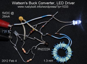
I assembled a two transistor LED driver buck converter for dropping the 12V input down to the 3.2 volts needed for the LED.  My problem seems to be that the circuit wants to act like a simple 22.2 mA current limiter, as if I took out the inductor and capacitor (the D1 is reverse biased and does nothing).   Then when I try to get it oscillating, the LED current goes higher than 22 mA, My expected behavior was that the circuit would take in a higher voltage at low current and convert it to a lower voltage at higher current.  I was hoping for 9V at 9 to 11 mA would give the LED a full 20mA.  Instead, the circuit is taking more than double that current and I´m guessing that a good part of that is wasted as heat and the LED is being overdriven – too  much current.

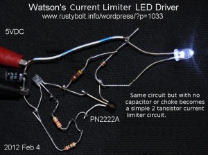
Feb 5 – I have changed most of the parts to values from one extreme to another.  I have not found an optimum point where the circuit did a better job of bucking the voltage.  All of the values gave an oscillating circuit that really behaved the same as a simple 2 transistor current limiter.  This current limiter can be visualized by removing the capacitor and replacing the choke with a short wire.

default

2012-01-30 Odd LED Dropping Resistor – Edible!

From Watsonseblog Jan 2010:

Very odd LED dropping resistor – edible!  There are several others of the same genre on Youtube but this one has LEDs.  Cool, an edible resistor!  I remember that the stores sold a hot dog cooker that was just s simple box with a drawer and electrodes.  It took about a minute to cook.  With 220V, it would take 1/4 that long!

default

2012-01-29 2 Transistor ¨Joule Thief¨ V. Booster

This circuit was posted to the files section of the Yahoo group Joulethief (you may need to join to see this).  I´m going to try to attach the pic but I couldn´t do it earlier,   You might also be able to see the picture here.

I built four versions of this circuit and made some measurements of each.  The first version (shown in the picture) used a 2N3904 for the output transistor and a 180 uH, 2.5 ohm DC resistance RF choke for the coil.  The second version I removed the RF choke and used a toroid with 10 turns of 24 AWG giving 171 uH and a DC resistance of less than 1/10 ohm.  The third and fourth versions were the same as the above two, but with the 2N3904 removed and replaced with a 2N4401.

Ver. — Xstr —– Coil — Isup —- Iled —– Freq

1 —2N3904 – Chok – 30mA – 9.2 mA – 71kHz

2 —2N3904 – Tor — 20mA – 6.3 mA – 61kHz

3 —2N4401 – Chok – 50mA – 15.7 mA – 38kHz

4 —2N4401 – Tor — 40mA – 15 mA — 48kHz

I noticed that with the 2N4401, when I changed from the lossy 2.5ohm RF choke to the toroid, the supply current went down but the LED current remained nearly the same. But with the 2N3904, the LED current dropped a lot when the toroid was used.  The only reason I can think of for this odd behavior is that the 2N3904 is mostly responsible for the poor results with the toroid – the loss doesn´t happen with the 2N4401.

With the 2N4401, the circuit has decent performance, putting out 15 milliamps to the LED.  This could be increased a bit by reducing the 470 ohm resistor to 220 ohms, and would give a few more milliamps LED current.  I would not consider using the 2N3904 due to its poor performance.

I have not yet tried changing the values of the capacitor to see if it will improve performance.  Most similar circuits I´ve seen use a smaller value, around 220 pF.

Back to experimenting…

© RustyBolt.Info/wordpress
CyberChimps