default

2012-05-05 watsonseblog – Make A Joule Thief Pictorial

From my late watsonseblog.blogspot.com, 2011-06-02

2011 Jun 02 Make A Joule Thief Pictorial

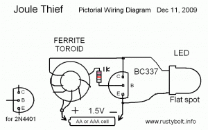
I’m attempting to make it simpler and easier to make a Joule Thief by using a pictorial diagram of a Joule Thief that’s, well, simple and clear. In order to keep it simple, I need the viewers’ input because what may look obvious to me may not be clear and simple to others. So, please leave a comment if there is something you don’t understand.

In this picture, the transistor has its flat face down, Emitter lead at the bottom, Base lead in the middle, connected to the resistor, and the Collector lead at the top. This is typical for American transistors. For European transistors such as the BC337, the flat face would be facing up. The LED’s cathode lead or flat spot is at the bottom, connected to the black wire and emitter lead. By the way, the black wire is held against the negative end of the battery by a button magnet.

default

2012-05-04 11 LED Lights From An Inverter!

Holy Smokes!  Peanutbutter291’s experiment (Youtube vid) has gone to extremes!  There must be way over a hundred dollars in the 11 LED lights, not to mention the socket to outlet adapters, power strip and 3-way taps, which must add up to another $40 to $50.  I was at the Big Box store this evening and noticed an inverter for thirty bucks or so.  This one plugged into the car’s cig lighter socket and put out a hundred watts at 120VAC.  This got me to thinking when I saw his video.  He could have saved over a hundred dollars and many hours of his time by buying one of these inverters and plugging his LED lights into it.  And he would still have plenty of power left over for when he needs to heat up his soldering iron.  Isn’t it crazy?  How much trouble we go to to get an experiment running, when there’s a lot simpler solution at the store.

Schematic  His comment gives a link to the schematic by lasersaber.  He calls this a “Super Joule Ringer 2.0” but I have no idea why he calls it a “ringer.”  The same high voltage winding that is used to drive the light is used to drive the base of the transistor.  The problem with this is that the reverse voltage on the base causes the emitter to base junction to break down like a zener, and this damages the transistor.  In order to prevent this, there should be protection connected across the base and emitter pins.  That’s easy and simple.  Connect two 3.3 volt zener diodes in series, with the end with the black band connected together.  Then connect the remaining ends to the emitter and base.  When the reverse voltage goes up to about 4 volts, the zener diodes conduct and prevent excessive voltage on the base.  Why two zeners?  Because a single zener with the cathode or band end connected to the emitter will prevent excessive reverse voltage.  But when the forward voltage appears across the base to emitter, and also across the zener, the zener will conduct and shunt the current away from the base.  Adding the second zener diode prevents this.

Another way to do this is to put 3 or 4 regular diodes in series. and connect the lead with the cathode or banded end to the base.  When the reverse voltage gets up to 1.8 volts or more, the diodes will conduct and protect the base against breakdown.  For moderate currents at higher frequencies, use 1N4148 diodes, or for higher currents at audio frequencies, use 1N4003 type 1 amp rectifier diodes.  I added the protection to his schematic and I’m attaching it here.  If lasersaber wants to add the picture to his site, and wishes to contact me to have this removed, he can email my yahoo.com address, acmefixer.

The cost of a few diodes or zeners is a few cents, so to my thinking, the choice is obvious.  In the case where the experimenter still wants to use this circuit without protection against E-B reverse breakdown, I have a solution.  I’ll sell you a carton of a hundred new (old stock) 2N3055 transistors (see the picture), and then you can just remove the “used up” one and put a new one in whenever you need to.   Ω

Update May 5

Peanutbutter replied to my comment:
@acmefixer1 The circuit is similar, but WITH a base bias resistor as shown in Improvements part 1. Yes, the circuit as shown is “hard” on a transistor, though current won’t back flow until VBceo is exceeded in reverse. In some cases a TVS, zener, or diode can be used; yes. However, in many cases this will STOP and prevent oscillation. So, protection via a positive bias allow oscillation AND prevents reverse current flow.

I don’t accept “the circuit is hard on a transistor…”.  What is happening is the circuit is missing protection against reverse breakdown of the emitter to base junction.  I’ve built the “Slayer Exciter” circuit which is very similar, and it uses a LED from base to emitter to protect against reverse breakdown.  The reverse breakdown protection cannot “STOP and prevent oscillation” because it is an open circuit and does not conduct during normal oscillation.  Only when the reverse voltage becomes excessive does it conduct and prevent reverse breakdown.

The addition of “positive bias” does not provide protection against reverse breakdown.  It does not “prevent reverse current flow”.  It is very easy to demonstrate how the current flows in the base lead.  Connect two red LEDs in parallel so that the cathode or lead with the flat spot of one LED is connected to the anode (no flat spot) of the other LED.  Disconnect the lead to the base and connect it to one pair of LED wires, and connect the remaining pair to the base, so now the two LEDs are in series with the base.  Power up the circuit.  If the circuit is not causing reverse breakdown of the base, there will only be a single LED lit, which shows that the base current is flowing only in the forward direction.  If both LEDs light up, then there is current flowing in the forward and reverse directions, and the base to emitter junction is breaking down in the reverse direction.

Any circuit design that intentionally subjects its components to destructive conditions is not a design, it’s stupidity, and the designer is not learning from his previous bad experience that there is a design deficiency.  Unfortunately disaster will follow if the design is not changed, and he/she deserves the consequences.

Someone might wonder why I have a whole carton of a hundred 2N3055 transistors lying around in my workshop.  Well, long ago, before I understood why my circuits would blow out power transistors, I had the opportunity to obtain a whole ‘brick’ of them for a very good price. So I took advantage of that opportunity.  Then I learned about how to prevent them from being damaged.  Ever since, my use (or abuse) of 2N3055s has dropped drastically, and I found that I really don’t need them as ‘spares’ any more.

Back to experimenting…

default

2012-05-03 Make A Power Saving Plug

on May 3rd, 2012 by - Comments Off on 2012-05-03 Make A Power Saving Plug

I read Big Clive’s web page on making a power saving plug, and was disappointed.  Disappointed because it is such a ripoff that it would be a violation of Federal Trade Commission rules had it been sold in the U.S.  Big Clive said that the capacitor had one lead cut, so it was effectively doing nothing.

But Clive gave no further information on the value of the cap or its rating.  If it is connected across the power line (“mains”) the rating must be X2.  From what I’ve read, the capacitor is designed to fail open so it will not be a safety and fire hazard when it fails.  More info about this can be found here (.PDF).  If the capacitor was not of the proper rating, it is probably best that the lead had been cut, for it could be unsafe otherwise.

It’s not at all clear to me (in both cases) what the schematic was supposed to accomplish.  Like he said, some of the parts just don’t do anything.  Somewhere along the line, someone may have found that the device was dangerous with the capacitor connected, and went inside and cut the wire to render it safe but ineffective.  What the law enforcement agency should do is confiscate all of them when they entered the port, and had them taken out of the supply chain so that the consumer would not waste their money and become a victim.

Perhaps someone could relabel them and sell them as night lights?  Probably not very bright.  I’m curious as to how many of these have been sold to unsuspecting consumers, and how many hundreds of thousands or millions of dollars someone has made at the expense of the consumer.


default

2012-05-02 Audio Compressor Limiter

on May 2nd, 2012 by - Comments Off on 2012-05-02 Audio Compressor Limiter

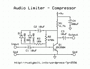
I found this circuit that uses an opamp with a pair of diodes in antiparallel in the feedback loop to reduce the opamp gain when the signal rises to a certain level.  I would think that this is more of a limiter than a compressor, since it cuts in at 0.6V and stays that way as long as the signal level is above 0.6V.  The author claims that it transitions smoothly and gives good results.

But my main interest is not so much about the performance, but how I can get this same principle to work on a simple 1 transistor circuit.  I came up with the schematic ( see attached) that might work, however I haven’t tried it yet.

default

2012-05-01 Light Sensor Circuit

on May 1st, 2012 by - Comments Off on 2012-05-01 Light Sensor Circuit

I watched this video on Youtube called Light Sensor Making Steps.  He shows a schematic at the beginning.  The problem is that when the light is bright, the CdS “LDR ” photocell’s resistance can go well below 1000 ohms, and then the photocell is passing as much or more current as the LED is using.  The total current to the circuit is much more than the LED current, and it is very wasteful, especially if the circuit is being powered by a battery, which will be drained much faster.

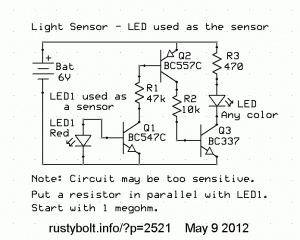
So I thought I should come up with a better circuit .  And it doesn’t have to use a CdS photocell.  Instead, it will use a red LED as a light sensor (see the schematic).

Another alternative solution is to put a resistor in series with the CdS photocell, to limit the amount of current it passes.  The transistor needs only a fraction of a milliamp to turn on and light the red LED.  I would say insert a 3.3k resistor in series with the photocell, and see how it works.

Also, remember that you do not have to source current through R2, you can sink current.  Swap the Q1 and Q2 transistors.  Put the BC557 first, with the cathode or flat spot of red LED connected to the base and the anode connected to +6V along with the BC557’s emitter.  The BC557’s collector then connects to the 47k, which then connects to the BC547’s base.


default

2012-04-30 Stepper Motor Drives LED – Clock?

on April 30th, 2012 by - Comments Off on 2012-04-30 Stepper Motor Drives LED – Clock?

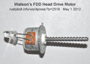
I’ve taken apart many disk drives, CD drives and floppy drives.  The magnets are awesome!  Another fun part is the motor.  In the case of floppies and CDs, the head stepper motor is small, relatively powerful for its size, and can be used as a generator to drive a red LED connected directly to it (see the picture).  The motor that drives the door opening mechanism and the disk drive motor will also generate enough power to drive a LED, but the voltage may be too low; a Joule Thief may have to be added to boost the voltage enough to light the LED.

I soldered the red LED directly to two of the four pins of the head stepper motor in the picture.  I can spin the shaft with my fingers and the LED will briefly light up brightly. The shaft is too small and unwieldy to spin with the fingers for any length of time.  I could tie some heavy string or dental floss between the ends of a straightened out paper clip to make a sort of bow.  Then I could wrap a turn or two around the shaft of the motor, and by moving the bow, the shaft would spin and light the LED continuously  – well almost.

Clocks and Ideas for Clocks  Bill “Botronics” Sherman sent me a link to his Nixie Clock project.  It uses a single Nixie numeric tube to flash the digits of the time one after the other.  The brains of the circuit is a microcontroller that divides the crystal frequency and outputs the correct digits.  He got some of the project from another Nixie clock seen here.  I viewed some of this other guy’s clocks and found them interesting.  One that is intriguing is the clock that uses an analog wiggle stick meter to display the digits – very retro; the meter may be more than 50 years old.

This got me to thinking about other alternative ways to display the time (Thanks, QS).  These small stepper motors from disk drives could turn a small disk with the numbers on it to indicate the time.  The clock would be even simpler than a Nixie clock.  All that is needed are a precision one second pulse source, a few stepper motors, some reed switches and magnets, and some heavy cardboard for the disks with the numbers.  The pulse would drive the seconds stepper motor and its associated disk.  The seconds disk would have a small magnet glued to the back of the disk, which passes by the reed switch every full revolution.  This pulse would then step the tens of seconds disk, and so on for the minutes and hours.  Some circuitry would be needed to make the stepper motor stepping pulses (the drive board from a battery operated clock?).  But I don’t think any microcontroller would be needed.  To set the time, the wheels could be turned by hand to the correct time.

I suppose the clock could be reduced to a single disk, like the Nixie clock.  But it would need a way of telling where the disk is as it spins around from one digit to the next.  That’s the nice thing about using several disks: since time always progresses from one second to the next, all that has to be done is to step the disk to the next digit.

I had another brainstorm about a clock.  There’s nothing that says that the dial has to be a circle with big hand and little hand, etc.  We may have seen the table clocks with the digits that are on little plastic tabs that flip down every minute and then disappear behind the next one.  Well, I thought that it might be possible to make an analog display by putting a piece of old 16mm film on sprockets and have a LED shine from behind to illuminate the digit on the film.  The film would be long enough to have a digit every 10mm, so 600 mm length for the seconds and minutes, and 120 or 240 mm for the hours.  The clock could be made to be very narrow, and long enough to accommodate the strips of film.  Seconds could be roughly gauged by small tick marks on the edge of each digit.

Here is another really cool clock, one that tells the time anywhere in the world, and whether it is daytime or nighttime.

Here is another link that I found that shows a guy’s unique computer project.  Wow, that must be noisy!

Comments?  Send to my Yahoo.com email address, acmefixer

default

2012-04-29 Ring Oscillator Teleport Transponder

on April 29th, 2012 by - Comments Off on 2012-04-29 Ring Oscillator Teleport Transponder

I’ve built and blogged a ring oscillator that works good for making LEDs look like marching lights on a marquee.  I think I could get 9 LEDs, the circuit and a 9V battery into an Altoids tin, and it would look cool.  I’d have to paint over the ‘Curiously..’ whatever on the outside, though.  The number of stages always has to be odd.   I got the schematic from Bill “Botronics” Sherman, here is his version in a Youtube Video.  His is running very slow; mine is much faster and has much more attraction to the eye.  Imagine it speeded up ten times or more.  He gives a link on Youtube to the .PDF schematic on his website.  I used 1 meg resistors and 0.1 uF capacitors between stages.  I used only three stages, and connected three LEDs in series for each stage. I put a 22k resistor across the LEDs to get the circuit to start at a lower voltage.  Each stage uses a 2N7000, which acts more like a vacuum tube or thermionic valve than like a transistor.

What I’m planning on doing is emulating Big Clive’s “Teleport Transponder” gizmo.  I plan on adding a mini reed switch to the bottom of the circuit board, and hiding a pill sized 6mm neodymium magnet between my fingers.  Then when it works for me, but others can’t get it to work, I’ll tell them it’s tuned to only transport human tissues that have my genetic code.  😉

Big Clive has a rather wry sense of humor… (from one of his projects)

This is also a good time to test the LED assembly in a handy USB port.
If there’s a muffled bang and the house lights dip momentarily, then you may need to call a computer service engineer.

🙂

Back to experimenting…


default

2012-04-28 LED Light Compared With Luxmeter

on April 28th, 2012 by - Comments Off on 2012-04-28 LED Light Compared With Luxmeter

Two years ago I decided that I wanted to get a light meter.  I had two old light meters for setting a camera, one was a Weston and the other a G.E.  Both were not sensitive enought to give an accurate reading of a LED.  I had some other choices, one was to use a CdS photocell connected to a DMM set to the kohms range.  The light from the LED would give a reading relative to other LEDs or another kight source, but it was not an absolute measurement.

Another way to compare two light sources is to use a grease spot (yes, read this for how it’s done).  But the LED is not like a candle flame or light bulb that radiates in all directions.  The LED is directional and may have differences in the intensity of the light across its beam, so the measurement could be more difficult.   It seemed that the CdS photocell would be the better choice.  But it and the ohmmeter make a comparison; the LED’s actual light output in standard units is not known.

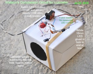
I found that I could buy a Luxmeter online for about $40.00 U.S., which seemed reasonable (it looks exactly like the one in this Youtube video).  I ordered one and when I received it I made a jig for it (see the picture).  The jig does two things: it holds the LED a fixed distance away and aims it at the luxmeter’s sensor head.  The jig also keeps out ambient light so the head only senses the LED light.  I used a cardboard box with a small hole cut for the LED and a large hole cut for the luxmeter’s sensor head.

The LED is a 10mm 1 watt white LED.  This allows me to measure more than a hundred milliamps, which would be much too high for a regular 5mm LED.

The switch on the top allows me to switch between the Joule Thief circuit shown in the picture, and an externally connected power supply.  With the switch set to the Joule Thief, the LED’s light output is measured with the luxmeter.  The JT is turned off, the LED is switched to the power supply and the power supply is adjusted until the luxmeter’s reading is the same as the JT reading.  The voltage across the large 100 ohm resistor (on the right) is then measured and the current calculated by dividing the voltage by 100 ohms.

Thus I am making two measurements: the actual light output of the LED in Lux, and comparing the light outputs of the JT and power supply  The on;y difference between the LED’s light from the Joule Thief and the LED’s light from the power supply is that the power supply is DC and the light is steady, whereas the JT’s current is pulsed so the light output would be pulsed.  The luxmeter is made for measuring the light from the fluorescent lights of a room, which is also pulsed at twice the line frequency (100 or 120 Hz), so I see no reason to believe that the pulsed light would give a different reading than the steady light.

I used this setup in my earlier blog where I compare the light output and current of a conventional Joule Thief with my Supercharged Joule Thief.

default

2012-04-27 Renewable Energy: Where Are They Today?

on April 27th, 2012 by - Comments Off on 2012-04-27 Renewable Energy: Where Are They Today?

I’m reading a timeline or chronology of the electricity in the U.K.  It has a listing with a few U.S. items under the years 1980 and later.  Indented text is from the chronology, my comments follow.

U.S. legislation —

1.  Power plant Fuels Conservation Act  provided for converting 80 U.S. power stations from oil-firing to coal-firing

1.  During the 1970s the two oil and gas crises, the last in 1979, drove everyone to attempt to wean the U.S from ‘foreign oil’.  This explains why we went from oil burning to coal burning power plants, with all their pollution.  It was better to have electricity with pollution than no electricity at all.

2.  Magnetic Fusion Energy Engineering Act  increased national research on fusion power.  New installations were a Tokamak Fusion Test Reactor at Princeton N.J.; the Mirror Fusion Test Facility at Livermore, CA; the Elmo Bumpy Torus Proof of Principle Experiment at Oakridge, TN; and Materials Fusion Irradiation Test Facility at Hanford, WA.  Act sought to commission a demonstration fusion power station by 2000.

2.  Magnetic fusion was supposed to make clean, pollution free energy with no radioactive byproducts, and save the world.  Here it is, 2012, and we still haven’t seen a single watt of commercial electricity made by fusion, after spending tens of billions of dollars trying to develop the technology.  What a waste.  If that money had been used to harness thermonuclear fusion by building solar power plants, we would have been much better off.  More on fusion power in this Wikipedia article.

3.  Wind Energy Systems Act  set a target for installing 800 MW of wind generation capacity in the U.S.A. by 1988

3.  I don’t know if that 800 MW target was met by that date, but today there is much more than that of installed wind generating capacity in the U.S.A. and it continues to grow.  The U.S. nameplate capacity was 47,000 MW at the end of 2011 (see Wikipedia article).

4.  Ocean Thermal Energy Conversion Research, Development and Demonstration Act  established a national U.S. target of 10,000 MW of O.T.E.C generating capacity by 1999.

4.  There is an OTEC system in Hawaii, but I’ve never heard of any OTEC power at 10,000 MW.  Another dead end?

5.  In 1981 a 3 MW wind generator was commissioned by Southern California Edison.

No doubt it was in the Altamont Pass, Calif.  Nowadays, one can drive through the pass and see thousands of wind turbines – they’re as thick as ants on an anthill!  Another wind farm is Banning Pass, on the way to Palm Springs, Calif.

6.  World’s first electric utility fuel cell power plant was commissioned in New York.  The 4.8 MW  prototype comprised 14 modules.

6.  We seldom hear of fuel cell electric generation.  I’ve heard of vehicular fuel cells that burn hydrogen, and give off zero pollution.

7. 1982  Wind Turbines – USA — between 1982 and 1984 over 2,000 wind turbines of 50 kW to 100 kW were installed at a wind farm at Altamont Pass, California.  Another 550 were planned.

7.  Looks like the 1980s were the years when wind turbines sprouted up like crazy over the landscape.  But they’re still installing them like crazy, as can be seen in this Wikipedia article.  The older, less powerful ones are being replaced by much more powerful wind turbines.  The picture in this article was so bad it was difficult to see the WTs, so I increased the brightness and contrast and attached it above – they are much easier to see.  In the Wikipedia article, the problem of wind variability is brought up, and one solution used in the U.K. is the Dinorwig pumping station.  When demand is low, the excess electricity is used to pump water up to a higher reservoir.  During peak demand, the water is let out and on the way down generates electricity from the same pumps.  It is also used to stabilize the variable wind output.

 8.  Solar energy- U.S.A. — two plants commissioned – “Solar One” near Barstow, California, a 10 MW central receiver pilot plant, and “Solar Total Energy Project” at Shenandoah, Georgia, the world’s first complete dish system.

8.  More about Solar One can be read in this Wikipedia article.  It has now been removed.  There is a new Solar One in Nevada that was built outside Boulder City.


default

2012-04-26 How to Power 50 LEDs from 5V

on April 26th, 2012 by - Comments Off on 2012-04-26 How to Power 50 LEDs from 5V

I got an alert with an Instructable question (pardon the poor txtng-like spelling):

How would i used a joule theif and power 10 to 50 led on a circuit if i used a 5v power supply or a battery.?

I wuld like to make a banner out of leds for my wife and i am wondering if it would b possible to do it using the joule theif method but instead of a battery use a 5v power supply. wat resistor wuld i need and is it even possible?

My answer was:

It’s very simple: you put a 100 ohm (brown, black, brown, gold) 1/2 watt or 1/4 watt resistor from the +5V to the lead on the LED that does not have the flat spot next to it.  The other LED lead with the flat spot goes to the negative 5V.

The white or blue LED will have a little more than 3 volts across it, and the resistor will have a little less than 2 volts across it, which will be about 18 to 20 milliamps, just about the max current for the LED.  If it is a red or orange LED, the voltage across it will be less, and the current will be more, around 30 milliamps, which is about the maximum for red LEDs.

The resistor and LED use 1/10 watt of power and will get warm.  If you put a lot of these in a confined space, they will get a lot warmer, so make sure they have good air circulation.  In all cases above, the LED will be a standard 5 mm diameter LED.

Each resistor and LED combination goes across the 5V wires, so they are all in parallel, no Joule Thief is needed, nothing else is needed (other than wire and a power supply). For fifty white or blue LEDs the total current is .02 A times 50 or 1 Amp, at 5 volts that is 5 watts.  Make sure your power supply can handle more than 1 amp, I would say at least 1.5 amps to be safe.  Get 50 LEDs and fifty 100 ohm resistors and get to work!

USB, Etc.  One thing I should have added is that this could be powered from a USB port or USB power adapter, but USB ports are rated for 1/2 amp, so you could use no more than 25 LEDs on one port.  But that’s maximum, so it would be safer to use less than 25.

A PC power supply could supply 5V at dozens of amps, but it requires that the pin that turns on the PS be grounded.  More can be found here about how to do this. By the way, I cannot be responsible for, and I cannot vouch for the safety or accuracy of this or any other website.

Higher Power LEDs  As I said, the above applies to the standard 5mm LEDs.  The higher power LEDs can be used, but the resistor will have to be changed to match the power of the LED.  For example, using a 1 watt LED, the current would be approximately 350 milliamps or 0.35 amp.  For 3.2 volts across the LED and 1.8V across the resistor, the resistance would have to be 5.14 ohms, but that is not a common standard value.  Instead, use a  5.6 ohm resistor.  At 1.8V and 0.35 amps, the resistor would dissipate 0.63 watts, so a 1 watt resistor would be needed.  Other LED powers could be accommodated with different resistor values.

Important Do’s and Dont’s

Do use adequate heat sinking and ventilation for your LED project.  LEDs make heat and LEDs can have their life shortened when they are too hot.

Do not put LEDs in parallel.  Why?  Because the LEDs have different forward voltages.  Say for instance, we put two LEDs in parallel, one with a forward voltage of 3.3V, the other with a forward voltage of 3.2V.  The 3.2V LED will  hog more of the current than the 3.3V LED.  The important point is that the 3.2V LED will get warmer, and the higher temperature makes the forward voltage drop.  With a lower forward voltage, it will hog even more of the current, and get even hotter, and this can continue until the LED either gets damaged from excessive current or its life is shortened.

Think of the two LEDs as if they were the edges of a brim of a coffee mug in the sink.  Say one edge of the mug’s brim is higher than the other (we put a knife blade under it).  When we pour water into the mug, the water will spill over the lower edge before it spills over the higher edge.  The current will flow through the LED with the lower forward voltage before it flows through the higher one.

Exceptions??  You’re probably thinking, “I bought one of those cheapo 9 LED flashlights and took it apart, and found that all 9 LEDs were connected in parallel on the round PC board.”  You are right.  How do they do it without burning up the LEDs?  I have some explanations but I have not verified them to see if they are valid.  First, the LEDs have forward voltages that are very close or the same.  This is helped by having all of the LEDs being from the same maker and the same batch.

Also, the thought occurred to me that they may have tested the LEDs to match their forward voltages, but I don’t think they would do this because of the expense and labor involved, unless their automated assembly equipment tested them during assembly.  Another factor is that these are in a flashlight that is used only briefly, for a few minutes at most.  The LEDs don’t have enough time to get hot, and the flashlight is used only a few hours per year, so any LED light degradation would not be noticed for years.

Efficiency  Some have expressed their concern about the low efficiency of this resistor and LED combination.  I calculate the efficiency at about the same or a bit more than a conventional Joule Thief.  The LED dissipates 3.2V times .018 amps or .0576 watts.  The resistor dissipates 1.8V times .018 amps or .0324 watts.  Total dissipation is .0576W + .0324W or .09 watts.  The LED dissipates .0564W / .09W or .64 of the total, which is 64 percent.  A typical conventional Joule Thief has an efficiency of 50 to 60 percent.  So the LED and resistor is a bit better and simpler to build.

© RustyBolt.Info/wordpress
CyberChimps