default

2012-05-15 Joule Thief To Power 300 LED Strip

I got this Google Alert for a request for a JT schematic.  The text of the original request and my reply are in the attached picture.

These request are quite common, and typical for the forums which discuss Joule Thiefs.  It is an up front indication that the requester has no clue whatsoever about what the Joule Thief can do or that it will not “make my LEDs more efficient”, which is another typical misstatement.

I have speculated about how the requesters may have been misled to believe that the Joule Thief is the answer to their problem.  One theory I have is that they see some Youtube video such as this one that makes the outrageous claim that the Joule thief can light up a string of hundreds of LEDs on Xmas tree lights “to full brightness” or something to that effect.  What the simple math tells us is that it takes about a tenth of a watt to light up each LED “to full brightness”.   So 300 times a tenth of a watt equals 30 watts.  Simple, no?  We will require about that much power to make a reasonable amount of light from the string of LEDs.

Somewhere there is this fundamental misunderstanding that we cannot get something for nothing.  The added electronics are going to need some of the power, and what’s left is what’s going to be output to the circuit, the LEDs in this case.  We can’t expect a Joule Thief to magically solve all of our problems.

When someone discusses a circuit, the reader should be informed of not  just the circuit’s advantages, but also of its limitations and shortcomings.  If they lack this information, they cannot make the correct decision on how suitable it is for their purposes.


default

2012-05-14 Watson’s Early Joule Thief Experiments

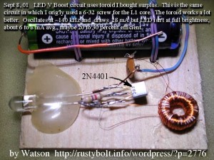
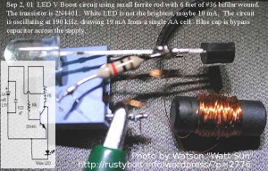
I started experimenting with the LED V boost circuit, which later became popularly known as the Joule Thief.  This pic, dated Sept 2001, is a not so good example.  I used 36 AWG wire, which is too thin and has too high resistance; that’s why it was drawing only 19 mA current from the battery – it should be 70 to 80 mA.  I made a mistake in the schematic – it shows a 10k resistor, which should be 1k.

The ferrite core had lots of turns of wire, but because it was very low permeability, the frequency was very high, 190kHz.  A typical JT today would have 25 turns max and a frequency of less than 100kHz.  I doesn’t have to be a toroid, though, but a toroid is convenient.

A few days later I changed the coil to a low permeability toroid, but again I used a lot of turns of too small wire.  I hot glued the circuit to a piece of thin plywood so I could keep the coil wires from being pulled loose.

Posted Aug 14, 2012.  Back to experimenting…

default

2012-05-13 +VE and -VE: A Disgrace And Dishonor

on May 13th, 2012 by - Comments Off on 2012-05-13 +VE and -VE: A Disgrace And Dishonor

In the past few years I have seen the symbols +VE and -VE pop up in schematics such as this example.  Ever since the great experimenters the likes of Volta, Ampere and Faraday passed on their theories to the whole world more than a century ago, the simple and effective symbols + and – have been used.   It is a disgrace and dishonor to attempt to change or add to these symbols something that is neither needed nor adds understanding.


Comments are disabled due to comment spam.  If you wish to comment send it to my Yahoo.com email address acmefixer and I will add it to the blog.

default

2012-05-12 Power Supply Self Destructs

on May 12th, 2012 by - Comments Off on 2012-05-12 Power Supply Self Destructs

This power supply circuit uses a LM317 or 7805 regulator chip to do the work.  The problem is that when the wiper arm of R1 is turned to the position closest to the top, it will short the output to the common or adjust pin.  This will cause the R1 pot to overheat and burn out and possibly damage the regulator and/or other parts in the circuit.  This is not a good thing to do.  The solution is to put a resistor between the top end of R1 and the output pin so that the total resistance cannot be less than a certain amount.  R1 is 10k so a resistor of 470 ohms seems to be a good choice to start at.  It will reduce the voltage adjustment slightly, but that’s better than burning up, now, isn’t it?

default

2012-05-11 AM Transmitter Pushing The Limit

on May 11th, 2012 by - Comments Off on 2012-05-11 AM Transmitter Pushing The Limit

I came across this AM broadcast band transmitter project from a guy in Greece.  It uses a single transistor to do everything, and a carbon microphone for audio modulation.

There are some major drawbacks here.  in Diag.4, the schematic shows the audio jack is connected directly across the R2, which has a few volts across it.  The typical experimenter would try to connect this jack to a CD player, not realizing that the current from the transistor could be going back into his player and doing damage to its circuit.  The solution is to put a 100 uF electrolytic capacitor in series with the center jack wire to block the DC from going into the player.

Further on, under ‘Component Variations’ he tells how he is going to increase the supply voltage to get more power and greater range.  This is a bad idea, and is going to burn out the transistor.  The best way to get greater range is to use a longer wire for the antenna (in the U.S. the antenna is limited to 10 feet or 3 meters).  For the AM broadcast band, the antenna has to be much longer: at 1000 kHz, the wavelength is 300 meters, so a 1/4 wavelength antenna will be 75 meters, or 250 feet.

To make the transmitter more powerful, raising the supply voltage is a really bad idea, as I’ve said.  The transmitter should use a MOPA (master oscillator – power amplifier) design.  One transistor is used for the master oscillator, so the circuit will not get hot and drift off frequency.  The power is increased with another transistor, and this is where the amplitude modulation is done.  With the modulation to the power amp, the signal can be modulated nearly 100 percent, something you can’t do with a single transistor.

He also talks about using a 2N3055 power transistor.  A 2N3055 is capable of putting out tens of watts at audio frequencies, but the AM broadcast band is a thousand times higher frequency, and the 2N3055 cannot put out much power, or probably more like no power at those frequencies.  For a watt or more at broadcast band frequencies, I would use one or more BD139 transistors, which are very inexpensive.  Put them in parallel for more power.  But the supply should not be higher voltage, it should be higher current for more power.

There is a lot of pirate radio information on The Web, but much of it is for the FM band.  Still, there are plans for AM transmitters that can put out quite a bit of power.  The amateur radio transmitters are capable of putting out a thousand watts.  Many of these higher power transmitters use vacuum tubes aka thermionic  valves.  An old 5 tube radio can be converted to transmit on the AM band.  The tube that is used to drive the speaker can put out a few watts on the AM band.

default

2012-05-10 Watson’s Weston VM

on May 10th, 2012 by - Comments Off on 2012-05-10 Watson’s Weston VM

A long time ago I wanted to get a digital panel meter that is small, uses very little power (LCD display), and does not require a power source that is floating, in other words it can be powered from the same power supply that it’s measuring. When it’s measuring current, this is important, since both measuring leads are nearly at the same voltage.  It seemed like every digital panel meter I came across required that the power be independent and isolated from the measuring leads. I got discouraged and gave up trying to find one.


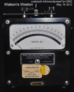
Several years ago I was lucky to buy this Weston mirror backed voltmeter at an ATCA telephone collectors show. It has a 3V range, which I extended to 15V with the precision resistors that I mounted on a piece of PC board, and screwed down to the top using the meter’s binding posts.  It uses a 1 milliamp movement, hence the label “1000 ohms per volt”.

Its accuracy is uncanny: I can eyeball the needle using the mirror to get rid of the parallax, and using the needle, set the power supply voltage to what looks like exactly 1.5V.  Then I put the DVM on the power supply, and incredibly the voltage is within 5 to 10 millivolts of 1.5V.  Its disdvantage is that it loads the circuit down with up to 1 milliamp of current, so measuring a higher resistance circuit is not going to be accurate.  But it’s great for setting the cheap power supply that has a 3 digit digital meter with only a single digit to the right of the decimal point.

Yeah, it’s big and bulky and it needs calibration.  But it’s probably been around longer than most of us have been alive, and it’s still almost as accurate as a DMM.  The GTC of California sticker means it was property of General Telephone of California, a division of GTE, AKA General Telephone, which is now known as Verizon.  Weston, Simpson, Triplett and a very few others were famous for their fine meters and meter movements.  It has a serial number at the bottom.  I wonder if Weston company is still around?  It might be possible to find, from their records, when the meter was made.

I also have a Wheatstone Varley bridge that uses a very sensitive meter, might be a Weston.  It’s on a shelf behind some other stuff, and I haven’t looked at it in years, since I have a HP DMM that’s more accurate.  I should donate it to the telephone collector’s show, but I keep hanging on to it because it’s got a beautiful oak case.  There’s just something so much better about old test equipment that newer, more accurate equipment in a plastic case just doesn’t have.

Back to experimenting…


default

2012-05-09 Small, Medium Signal Amps – talkingelectronics.com

I came across this column in talkingelectronics.com where the author discusses small signal and medium signal amplifiers.  This medium signal term is one that I’ve never heard used before, and I’ve read a lot of literature that uses the small and large signal terms.  I’ve heard the small signal term applied when an incremental term is shown, such as when talking about the small signal current gain, hfe.  This is applied when the signal is a minor part of the DC operating point, or even when the signal is a major part, as long as it’s a part, not the whole.

The large signal term is used when talking about the absolute value such as when talking about hFE. This means the transistor’s large signal current gain is the ratio of the total collector current divided by the total base current. So 1 milliamp Ic divided by 10 microamps Ib gives a large signal current gain of 100.

Another term he uses is “the capacitor transfers…”  Here is part of his paragraph:

Both stages in Fig 62 produce a high gain but the final gain will depend on the amount of energy each capacitor will transfer.
For instance, the 22k will pull the 10u high but the 47k discharges the 10u and so it will be partially charged for the next cycle. This means the energy transfer will only be equivalent to a load resistor of 47k.

The “load resistor of 47k” doesn’t agree with what I’ve learned.  The 100k and 47k bias resistors are a voltage divider and also have a Thevenin equivalent resistance and voltage source.  The Thevenin equivalent resistance of the pair is the same as if the two resistors are in parallel, or Rth = 31.97k.  The Thevenin equivalent voltage source is 3.197 volts.  These are part of the load that the transistor sees.  And the author forgot that the transistors are operating in the linear part, so the bases of the transistors act like a load resistance.   The base of the second transistor loads the first transistor, so the load is even lower than the Rth.  In this case, the transistor’s base is probably less than a thousand ohms.  This means the 47k is insignificant.

He talks about “discharge and partial charge..” of the 10u coupling capacitor.  From what I understand, the 10u capacitor has a very low impedance at audio frequencies and to the AC signal it is as if the capacitor is not there, it is only blocking the DC from one stage to the next.  Because the AC voltage across the capacitor’s very low impedance is very low, the “charge and discharge” he talks about does not seem to matter (the capacitor is initially charged when the amp is powered up, and discharged when it’s powered down).  For example, we will assume that the second stage has a voltage gain of 100.  Therefore the peak-to-peak voltage at the base must be less than the supply voltage (10 volts) divided by 100, or 1/10 of a volt.  Any higher voltage and the signal at the second collector would be clipped and distorted.  The voltage across the 10 uF coupling capacitor is a very small fraction of that 1/10 volt.

Another point he doesn’t talk about is the value of some of the electrolytic capacitors used for bypassing (I did later find where he discusses bypassing capacitors).  One example is the bypass capacitor across the emitter resistor.  In the text below Fig.61b he calls the emitter resistor “negative feedback”, but negative feedback in its true sense is taking some of the output of an amplifier and feeding it back into the input in the opposite polarity so that it reduces the gain of the amplifier.  Putting the resistor in the emitter is not an example of this.

From what I’ve read, the value of the emitter bypass capacitor should be ten times higher than that required for its reactance to match the emitter resistor at the lowest frequency the amp is designed to pass.  For example, the amp has a 220 ohm emitter resistor, and is designed to pass 32 Hz.  The reactance of a 22 uF capacitor is approximately 220 ohms at 32 Hz, so a 220 uF capacitor, ten times higher, should be used.  If instead the 22 uF capacitor was used, then it would have 220 ohms reactance at 32 Hz, and that in parallel with the 220 ohm emitter resistor would cause the signal to be rolled off (amplified less) at low frequencies.  This capacitor should be large for good low frequency response.  But in some cases, the designer may want low frequencies attenuated, so the capacitor can be a smaller value.

He then goes on to explain where he believe is is necessary to match the output of an amplifier to the load of the following stage.

Background  In the early days of electronics, when single transistors were used to amplify a signal, typically audio, the stages of amplification were coupled with matching transformers, so that the higher impedance of the output would get matched to the lower impedance of the following stage.  But matching transformers were expensive, were optimized for a limited part of the audio frequencies, and prone to picking up hum and other magnetic interference, so they were replaced with R-C coupling, or resistance-capacitance coupling.  The electrolytic capacitors could be made large enough to easily couple the lowest audio frequencies to the next stage.  The next stage could have its input impedance increased by adding the emitter resistor, with some sacrifice in stage gain.  But germanium and then silicon transistors were cheaper, and it was cost effective to add another transistor than try to match the stages with transformers.

Then the opamp IC came along, with the 741 becoming the post popular.  Dozens of transistors could be included to make a high gain audio amplifier in a single package.  Later, higher performance opamps came on the market, with 2 or 4 opamps in a single package, such as the 1458 and LM324.  For the last few decades the audio designer has used opamps in place of transistors for most of the gain in the audio equipment.  But I digress.

Back to his eBook.  In any case, he dwells on this subject of matching the stages for maximum transfer of signal.  This is a good idea when dealing with RF, especially VHF and above because of the need for power output.  But for audio it is a non-issue.  Nowadays it is most common to find the output of a stage is much lower impedance than the following input.  This keeps the wide bandwidth of the signal, and has other benefits such as with noise. In fact, audio designers have to be concerned about having too wide a bandwidth which can cause instability if an amplifier is loaded with a capacitive load.

Referring to his figures 56 through 61b.  He calls this a “Bridge”; I’ve never heard it called that before; I’ve heard the term voltage divider used.  He shows the base bias resistors Ra and Rb.  He states that in order to keep them from loading down the previous stage, “.. they have to be as high as possible.” And he uses 1M and 470k in his examples.  In the textbooks, they teach us that these resistors are chosen to dominate the impedance looking into the stage’s input, since the emitter degeneration resistor causes the base to have a higher impedance.  The values chosen are typically 100k and 10k for Ra and Rb respectively.  Why so much lower than what he says is necessary?  Because these resistors have to keep the bias voltage steady at temperature extremes, especially at high temps where the transistor’s gain and leakage can become excessive.  Using the high values he says to use can become a problem at higher temperatures.  If you want to test it, put your amplifier in your car on a warm sunny day and see how well it works when the sun gets the amplifier hot to the touch.

Another one of his statements I take issue with:

However the capacitor on the input will produce losses from one stage to the other and the capacitor on the output will reduce the gain of this stage.

The capacitor is there to block the DC current from going outside of the stage.  At audio frequencies the capacitor has a very low impedance and there is almost no signal lost when it goes through the capacitor from one stage to the next.  Perhaps he is experimenting with 25 year old capacitors that are marked 10 uF but have dried up inside so that their actual capacitance is almost nothing and the signal loss across this capacitor is excessive.  If I found that my meter measured a volt or more of audio frequencies on one end of the capacitor, but a much smaller amount on the other end, I would immediately know that this capacitor is bad and needs to be replaced.

In other parts of his “eBooks” he again goes into this distractive mode where he dwells on something that seems to be a minor point, and makes a mountain out of a molehill, so to speak.  Yet, as in the above example, he skips over other important points.  He has a very large amount of good schematics and literature, but it’s my opinion that he has a way to go before he can say that it will make a good text for learning about electronics.

One suggestion I have for anyone who wants to learn about electronics is to buy the book “The Art of Electronics” by Horowitz and Hill (search Amazon for it).  This book is expensive, so you could try to find it in a library, but it’s not the kind of text you can borrow for a few weeks and get everything you need from it.  It really needs to be studied on and off for a length of time to get its full potential, which is a wealth of information.  I use it as a reference for much of my electronics design.  I have not noticed a single instance in the “eBooks” where the author quotes any electronics reference material.  He implies that his “eBooks” and website make a good tutorial for learning electronics.   I think it would be a good idea if he could point the reader to other references so the reader can get more and broader information on this subject.

Update May 13 – I continued to read other parts of his columns.  I came across this item in his digital column:

How can you tell a DIGITAL CIRCUIT from an ANALOGUE CIRCUIT?
1. Absence of capacitors. There are NO capacitors in a DIGITAL CIRCUIT.
2. A switch or push-button will be activating the circuit.
3. The circuit will be driving a DIGITAL or ON – OFF item such as a relay or globe.

Well, I can think of a digital circuit that uses capacitors.  A counter circuit is preceded by a Schmitt trigger to eliminate noise and make a fast risetime pulse.  This is then coupled to the counter circuit through a small value coupling capacitor.  For number 2, my counter example above is activated by a photocell that puts out a pulse every time a light beam is broken.  No switches or pushbuttons are used.  For number 3, my example counts the pulses and outputs the total to a numerical display.  No relays or globes (lamps) are used.  So far he has struck out on all three of his narrow-minded definitions.

So far, I get the feeling more and more as I read that a neophyte might feel he has been misled after reading his “eBooks” and then later learning the other side of the story from other textbooks.

default

2012-05-08 3V – 9V Converter, 2 Transistor Push-Pull

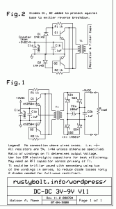
I drew this up back in 2000 when I was developing a converter to run a 9V transistor radio from 2.4 to 3V.  I decided that 9V batteries were too expensive and it would be better to make an efficient converter that would use AA cells or rechargeable AA cells.  The converters worked for the FM band but caused a lot of RF interference on the AM band.

In Fig.1 the 1k resistors are connected from the base of one transistor to the collector of the other transistor.  This uses the inverted signal on the opposite end of the transformer’s primary as the feedback, to keep the transistors oscillating.  Since the primary winding is center tapped, the opposite end of the winding has the supply voltage with the opposite polarity AC voltage on it.  In other words, if the Q1 collector has just switched off, then the voltage rises to 6V.

default

2012-05-07 Full Duplex Intercom from Redcircuits.com

I was perusing this circuit on Redcircuits.com when I noticed the capacitor C4 seemed to be backwards – the plus should be on the left.  I contacted the author and he said that he would correct it.

The idea of talking and listening at the same time “full duplex”, which is technically a communications term, not an audio term, is a very old concept.  Since the early days of telephones, the handset has had this feature for more than a hundred years.  But for some reason it was seldom if ever applied to an intercom system.

In reality, the way it works is the amplified  audio from the microphone is fed onto a bus with the speakers of both (or all in the case of 3 or more stations) outputting the audio to the listening area.  The audio from the local microphone is cancelled out so there is no feedback howl, and you don’t hear your own voice in the speaker.  This is called anti-sidetone in the telephone lingo.

In the schematic he shows the two stations connected together with shielded cable.  There can be some major issues with this method.  If the stations are separated by some distance, say 50 feet or 15 meters, the difference in the power line ground potentials can introduce hum between the two ends.  One solution is to run the power supply wires from the master to the other station(s) and leave the other stations ungrounded.  Hopefully this will help a lot in reducing the power line hum.

Another solution is to isolate the stations with a 1 : 1 transformer.  This has safety advantages if the transformer is able to withstand power line voltages or even higher voltages.  It also allows the connecting cable to be a much cheaper twisted pair telephone wire  instead of more expensive shielded cable.  And since the line is balanced, it can be run over considerable distances.  This is how the telephone company can have telephones thousands of feet away from the central office with very low hum and interference.

One transformer that works is the 600 ohm 1 : 1 transformer that I wrote up in my blog.  These have four windings so I suppose one could connect four intercom stations together.  But no real need to do that, since every intercom station can have a transformer, and there will be a single twisted pair “bus” running between all stations.

The original schematic shows a single collector resistor R5 for both stations.  If transformers are used, there will be no DC continuity between stations, so each station will have to have its own collector resistor.  R5 is 2.7k, so each station could have its own 5.6k resistor.

Other issues  The author uses the TDA7052 audio power amplifier chip to drive the speaker.  This makes good sense because it’s inexpensive and simple, taking up very little circuit board space.  However I’ve never seen these ICs for sale in any electronics store such as Radio Shack.  I can get the LM386 audio power amplifier chip for a reasonable price from R-S and other similar stores.  Or I can also build a simple audio amplifier out of discrete parts, a few transistors, resistors and capacitors, that will do an adequate job.  The LM386 is a good choice for 1 watt of audio output which should be loud enough with a decent speaker.

One other issue is microphone volume.  There are two factors here.  Neither station has an adjustment for the microphone volume.  I’ve found that there is a wide variation in the sensitivity between electret condenser microphones from the same maker.  One may be high, the next may be low.  This may have unwanted consequences for the intercom.  Another factor is how close do the participants want to be in order to be heard well.  If one station is in a high noise level environment, they may want the mic sensitivity to be very low, and will have to speak close to the microphone.  The other station may be in a large room, and the participant may want to be heard at various locations, both close and far.

For a two station setup, these issues may be adequately managed by the volume controls as shown.  There may be a problem for more than two stations,  or if there is a long distance or there are large losses between stations.

One other factor that is often not addressed is the low frequency response of the telecom system.  Low frequencies below 300 Hz do not carry much voice intelligence.   This intercom system has good low frequency response, and that may be a problem if there is a lot of background noise from machinery or other low frequency generators.  In that case, it may be necessary to limit the low frequency response.  Reducing C1, C3 and C4 would be a good choice.

Back to experimenting…

default

2012-05-06 Watsonseblog – JT Transistor Switch

2011-04-18 2011 Apr 18 JT Transistor Switch

I thought that it would be a really great idea to put several transistors on a switch so that I could switch between transistors and compare their performance.

I only have to connect the base and collector leads to the switch. The emitter lead is almost always connected to the negative or common or ground or earth connection, so it does not need to be switched. This means I need a 2 pole, multiple throw or multiple position switch. I figured that 5 or 6 positions would handle most of the common transistors used in a JT.

I got on the web and looked up a 2P5T switch and came across some at SurplusSales. As I figured, the solution would be a rotary switch. But I got a bit of sticker shock when I found they wanted up to $45 apiece for a rotary switch.

I started thinking about an alternate method of switching. The first thing that popped up in my mind was to use some jumper strips. These are like the ones that are (or were) on the back of hard disk drives, to allow you to select master, slave or cable select. I could put two of these on a PC board, one for the base and one for the collector. I just pull the jumpers and move them to a different transistor. It’s a bit slow and tedious, but it would probably work okay.

Then I thought about the setup I made years ago for two rooms that we used at different times of the year. One room was used during the peak periods, and then we moved across the hall to a smaller room during the last few weeks. Every time I moved the telephones, I had to pull off the jumper wires and move them to the other room.

This got really old really fast. So I took 2 male and 1 female DB-25 connectors like the ones used on the PC end of the parallel printer cable. I needed to move four phones or 8 wires, so I could have the female connector wired so that both rooms connected to it, along with the feeds from the central office. One of the male connectors was configured for routing the wires to the first room, and the other male connector was for routing the wired to the second room. I just pulled off one connector and put the other one on, and Bingo! The phones were moved to the other room.

This gave me a brainstorm. I have a lot of DB-9 connectors from old mouse extension cables. I can put a female 9 pin on the Joule Thief circuit, and take several male connectors and solder a transistor to each one. I really only need three of the 9 pins, but I don’t have three pin connectors. I can solder up as many transistors to the connectors as I want, and swap a transistor in a matter of seconds. COOL!

Another thing this allows me to do. I can solder different resistors or coils to the pins and switch them too. I can use a completely separate connector setup for swapping the coils, which have four wires.

Suppose I didn’t have the 9 pin connectors. I have a ton of power cords that seem to accumulate over the years from old PCs, monitors, printers, etc. Each power cord as a three pin plug on the end, and I could cut it off with a few inches of wire and solder the transistor to the three wires. Then I could use a socket and solder the JT to it. Then I just unplug the transistor and plug another one in. It’s a bit harder to unplug than the 9 pin connector, but it has large contacts for very low resistance connections.

Back to experimenting…

© RustyBolt.Info/wordpress
CyberChimps